EP1008971B1 - Überwachungssystem, basierend auf einer Hängevorrichtung für elektrisch zu kontaktierende Gegenstände - Google Patents
Überwachungssystem, basierend auf einer Hängevorrichtung für elektrisch zu kontaktierende Gegenstände Download PDFInfo
- Publication number
- EP1008971B1 EP1008971B1 EP99123612A EP99123612A EP1008971B1 EP 1008971 B1 EP1008971 B1 EP 1008971B1 EP 99123612 A EP99123612 A EP 99123612A EP 99123612 A EP99123612 A EP 99123612A EP 1008971 B1 EP1008971 B1 EP 1008971B1
- Authority
- EP
- European Patent Office
- Prior art keywords
- monitoring
- hanging
- article
- fixing
- unit
- Prior art date
- Legal status (The legal status is an assumption and is not a legal conclusion. Google has not performed a legal analysis and makes no representation as to the accuracy of the status listed.)
- Expired - Lifetime
Links
Images




Classifications
-
- G—PHYSICS
- G08—SIGNALLING
- G08B—SIGNALLING SYSTEMS, e.g. PERSONAL CALLING SYSTEMS; ORDER TELEGRAPHS; ALARM SYSTEMS
- G08B25/00—Alarm systems in which the location of the alarm condition is signalled to a central station, e.g. fire or police telegraphic systems
- G08B25/01—Alarm systems in which the location of the alarm condition is signalled to a central station, e.g. fire or police telegraphic systems characterised by the transmission medium
- G08B25/018—Sensor coding by detecting magnitude of an electrical parameter, e.g. resistance
-
- G—PHYSICS
- G08—SIGNALLING
- G08B—SIGNALLING SYSTEMS, e.g. PERSONAL CALLING SYSTEMS; ORDER TELEGRAPHS; ALARM SYSTEMS
- G08B13/00—Burglar, theft or intruder alarms
- G08B13/02—Mechanical actuation
- G08B13/14—Mechanical actuation by lifting or attempted removal of hand-portable articles
- G08B13/1445—Mechanical actuation by lifting or attempted removal of hand-portable articles with detection of interference with a cable tethering an article, e.g. alarm activated by detecting detachment of article, breaking or stretching of cable
- G08B13/1454—Circuit arrangements thereof
-
- G—PHYSICS
- G08—SIGNALLING
- G08B—SIGNALLING SYSTEMS, e.g. PERSONAL CALLING SYSTEMS; ORDER TELEGRAPHS; ALARM SYSTEMS
- G08B13/00—Burglar, theft or intruder alarms
- G08B13/02—Mechanical actuation
- G08B13/14—Mechanical actuation by lifting or attempted removal of hand-portable articles
- G08B13/1445—Mechanical actuation by lifting or attempted removal of hand-portable articles with detection of interference with a cable tethering an article, e.g. alarm activated by detecting detachment of article, breaking or stretching of cable
- G08B13/1463—Physical arrangements, e.g. housings
Definitions
- the present invention relates to a monitoring system with an associated hanging device for Suspension of objects to be electrically contacted, in particular works of art, which provided with electrical safety and / or lighting devices.
- the invention relates Furthermore, a monitoring unit for objects of the type mentioned.
- a monitoring system of the generic type is from the article "Protecting Paintings from Theft "by J. R. Knisley, Electrical Construction and Maintenance 76 (2/1977), page 62 it is a theft protection device for exhibited paintings, with the wall behind the suspended paintings metal rails are attached, which have three-core cable with corresponding plugs are electrically connected to each other, each rail for each image one Socket has, in which a three-pin plug can be inserted to by means of a three-wire Cable to connect a miniature switch with the three-wire system of the rails. Every mini-switch is attached by means of a wood screw and an adhesive surface on the back of the painting frame. In In this position, the circuit is closed by the switch.
- a motion detector for a security system is known.
- This detector provides a movable piezoelectric arm or lever which is in contact with a to be protected, e.g. Art object can be brought. If the object is moved, is over a associated special electronic circuit generates an output signal or an alarm.
- the circuit also provides a number of oscillators.
- WO 98/56182 Erf. Wegmann a method for monitoring a predetermined Monitored area specified.
- the method uses a detection device which is at least to have a video camera and / or a microphone. Their signals become automatic Signal analysis supplied.
- the procedure requires on the one hand a powerful computer hard and Software and, on the other hand, is more likely to be used in static situations, i. in the absence of Persons or moving objects within the surveillance area.
- a monitoring system and an associated Hanging device for hanging objects to be electrically contacted to create, which is characterized by particularly simple handling and application and the most convenient Hanging the items allowed.
- the hanging device according to the invention is very inexpensive, visually appealing and user-friendly.
- the monitoring unit according to the invention can be inexpensive be produced and is still reliable.
- the monitoring system according to the invention offers a high safety standard with convenient operation, and provides a simple way for a good sensitivity.
- the fasteners may be formed so as to ensure eligibility to which the current paths or each contact element produces an electrical contact. This allows one uniform formation of each fastener, so that only uniform basic type of Fasteners is required.
- At least two types of Be provided fastening elements which are characterized by the arrangement of their contact elements distinguish that in the suspended state at each fastener type, the at least one Contact element contacted another current path.
- each fastener is substantially mirror-symmetric with respect formed its center plane, wherein two contact configurations are provided, between which can be selected by rotation of the orientation of the fastener by 180 °.
- a second embodiment of the inventive fasteners is the Ensuring eligibility achieved in that only one type of contact elements is provided and each contact element before hanging the fastener at different locations of the Fastening element can be used to determine the current path to be contacted.
- the basic type of fasteners before insertion on the desired Contact configuration set is the basic type of fasteners before insertion on the desired Contact configuration set.
- the selectability can also be achieved by: at least two types of contact elements are provided and the contact elements before hanging the fastener to be used at a certain point of the fastener, wherein the choice of the contact element type determines the current path to be contacted.
- selectivity can also be achieved by that only one type of attachment unit, a single type of contact element and only a single one Variety of fasteners is provided, which by targeted localization of contact and Attachment made on or on the mounting unit a desired contact can be.
- the attachment unit is preferably formed like a rail, wherein it is an interior partially may include enclosing profile part and each flow path as in the interior space on the profile part applied busbar is formed, wherein the profile part is preferably electrically insulating is trained.
- the contact elements are preferably designed as a sliding springs.
- the profile part is in a first embodiment, preferably channel-shaped with three substantially closed sides and one provided with a continuous elongated opening side formed, wherein the fastening elements can be suspended by means of the opening in the profile part.
- the profile part can be channel-shaped with three sides, with its rear side is attachable to a wall, the front is substantially open and the top with a first slot is provided and the bottom is provided with a second slot, wherein the Fastening elements are hooked with its upper end in the first slot and with its lower End in the second slot can be latched.
- panel parts are provided in the opening or the open side of the profile part can be used and preferably with contact elements for contacting the current paths and with are conductively provided with these contact elements connected electronic devices.
- the contact elements can be so be formed so that they serve to hook the fasteners in the mounting unit.
- the fastening unit preferably comprises a plurality of space-fixed to be mounted in a row Holding elements and at least two parallel pipe or rod-shaped current guides, wherein the Power guides are held by the holding elements.
- the contact elements are designed so that they can each be suspended in one of the current guides.
- the selectability of the contact configuration thereby becomes achieved that the contact configuration of the orientation of the fastener when hanging depends.
- each fastener has an eyelet for hanging a to be hung with the Subject-related hanging element, which is conductively connected to the or each contact element is.
- the hanging elements are preferably designed as electrically conductive ropes or chains.
- at the objects to be hung are preferably works of art which are associated with electrical safety and / or lighting facilities are provided.
- the current paths are with a power source and / or a control unit connected to an electrical contact between the Power source and / or the control unit and the corresponding safety and / or Make lighting devices on the art objects on the hanger.
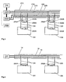
- the monitoring device shown in Fig. 1 is used to monitor on ropes 12A, 12B in an exhibition space suspended pictures 10A, 10B.
- Each picture 10A, 10B is on its back with a resistor RA and RB, respectively, which conductively connected to the cables 12A and 12B, respectively is.
- Each image 10A, 10B has associated therewith an individual resistance value to store the images for To make monitoring device distinguishable.
- a rail 14 attached, which with two continuous current paths 16 and 18 is provided, which are each connected to a control unit 20, which from a power source 22 with Power is supplied.
- the ropes 12A, 12B are formed as electrical conductors, preferably as Metal cables, and are connected at one end in each case with one of the current paths 16 and 18, respectively for an electrical connection between the control unit 20 and the respective resistor RA or RB worry.
- the resistors RA and RB are thus in an electrical parallel connection arranged, wherein the control unit 20, the current through the formed by the parallel circuit Total loop detected and in case of deviations from a predetermined setpoint an alarm signal to a Alarm device 24 sends, which then generates an audible or visual warning signal.
- each Removing an image 10A, 10B by unhooking at least one of the ropes 12A, 12B increases that Resistor in the overall loop and can thus be detected by the control unit 20.
- each resistance value is given only once, the control unit 20 can from the detected Resistance change determine which of the images is being manipulated.
- a digital form of a monitoring device is shown, wherein the identification of each image 10A, 10B via a logic unit mounted on the back of the picture frame 150a, 150b takes place, which in each case comprises a microprocessor as an essential component. It will each image 10A, 10B by a digital code value assigned only once, which is transmitted digitally Memory, dip switches, wire bridges and the like is fixed to the logic unit 150a, 150b, identified.
- the communication between the control unit 120 and the logic units 150a, 150b is via a 3-wire serial bus system (e.g., 12C bus).
- the mounting rail 114 includes to For this purpose, three parallel current paths 116, 117, 118, wherein the current path 116 as a ground terminal serves and the current paths 117 and 118 serve as receiving or transmission line.
- the current paths 116, 117 and 118 may also serve as power to or for the logic unit 50a, 50b will be one or two additional power lines and corresponding additional ropes for the Power supply of the logic unit provided.
- the monitoring function is realized so that the Control unit 120 via the bus system, d. H.
- the current paths 116, 117, 118 and the cables 12A, 12B Sends signals to the logic units 150a, 150b, which receive them and in response to the the code unit assigned to the special logic unit 150a or 150b.
- the control unit 120 In the absence of a Acknowledgment signal triggers the control unit 120 by a corresponding alarm signal to the alarm unit 24th an alarm. Since the acknowledgment function is different for each image, the control unit can 120 recognize which image is a manipulation.
- FIG. 3 another digital form of the monitoring device is shown, wherein instead of a Three-wire bus system is a simpler bidirectional two-wire bus system is used, which at the same time can take over the power supply of the logic unit 250A, 250B.
- the Mounting rail 214 has two current paths 216, 218, with which the electrically conductive cables 12A 12B are connected to form the two-wire bus system, this bus system both the Data exchange between the logic units 250A, 250B and the control unit 220 as well as the Power supply of the logic units 250A, 250B takes over.
- the mounting rail has 214 two current paths 226, 228, which as a power supply for lighting elements 252A, 252B serve, which are each attached to the mounting rail 214 above each image 10A, 10B.
- the lighting elements 252A, 252B may be, for example, ceiling lamps or a Light emitting diode arrangement to protect the color pigments of the painting act.
- the attachment and Contacting of the lighting elements 252A, 252B can, for example, also via electrical conductive ropes or cables 254A, 254B, which are connected to the current paths 226, 228.
- the power supply of Lighting elements also via the provided for the bus system current paths 216, 218 takes place, so that in this case the additional power supply tracks 226, 228 can be omitted.
- the Lighting elements 252A, 252B may further be provided with a motion detector 256A, 256B, its power also via the contact strips 226, 228 takes place and the over the current paths 216, 218 is connected to the control unit 220 in order to detect conspicuous movements in the area of the images 10A, 10B to the control unit 220, which then optionally an alarm signal to the alarm unit 24 sends.
- the motion detector 256A, 256B may operate optically or capacitively.
- a pre-warning function may also be implemented to indicate when a person or object comes too close to the images 10A, 10B.
- the motion detector 256A, 256B may also serve to only illuminate the lighting elements 252A, 252B when a person is near the corresponding image 10A, 10B On the one hand to save energy and on the other hand, the color pigments of the images 10A, 10B as possible to burden little light.
- the logic units 250A, 250B may be further configured to communicate with the Control unit 220 in addition to or alternatively to the use of the bus system by wireless means accomplish, wherein the logic units 250A, 250B are then designed as a transmitter / receiver and the control unit 220 is equipped with an additional transceiver unit 258 (in FIG. 3) shown in dashed lines).
- the lighting elements 252A, 252B may be attached to the images 10A, 10B and be via the electrically conductive suspension cables 12A, 12B of the images 10A, 10B, which are connected to the current paths 16, 18 the mounting rail 14 are connected, which in turn are connected to the power source 22, with Power supplied.
- the lighting elements 252A, 252B may also be "intelligent", i. H. with power switch and decode logic, so that a centrally controlled selective on / off individual or all lighting elements is possible. This control function can be over the Power supply lines or can be realized by additional control lines.
- Fig. 5 shows an alternative embodiment in which the lighting elements 252A, 252B are not on the images 10A, 10B are attached, but are directly clamped to the suspension ropes 12A, 12B.
- the power cables 12A, 12B should be insulated accordingly.
- the electrically conductive suspension cables can be used for safety reasons or in the interests of a be provided as possible interference-free operation with an external insulation.
- a Suspension rope also provide for two electrical connection lines, e.g. in the form of a coaxial or Twisted pair arrangement.
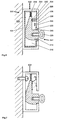
- FIG. 6 shows a first embodiment of a mounting rail with two current paths, as they Rail 14 in the monitoring or lighting systems shown in FIGS. 1 and 4 as a rail 14th can be used.
- the overall designated by the reference numeral 300 in FIG Mounting rail comprises a channel-shaped profile part 302, which is made of metal, for example and is secured with its back 304 to a wall 306.
- the front side 308 of the profile 302 is with an elongated through-opening 310, through which or in which a Fastener 312 is mounted in the profile 302, which has a body 314 by means of a Pressure spring 316 is pressed in the space 302 bounded by the interior 318 down, and a screwed into the body 314 screw eyelet 320 comprises.
- the interior 318 and the Opening 310 are lined with an insulation 322.
- On the inside of the front 308 are two parallel spaced busbars 324 and 326 are provided, which by means of an insulation 328 against the profile 302 are isolated.
- a self-contained contact spring 330th provided in the configuration shown in Fig. 6 as sliding contact with the upper Busbar 324 is in electrical contact.
- the body 314 and the eyelet 320 are conductive formed so that the sliding contact 330 makes electrical contact between the upper busbar 324 and the screw eyelet 320 manufactures.
- one of the electrically conductive Hang elements 12A, 12B are hung to one pole of an electronic monitoring element on an object 10A or 10B to be monitored with the busbar 324 to connect.
- the Screw lug 320 may also use another suitable element, such as a hook become.
- the fastening element 312 is basically displaceable along the profile 302, wherein the Contact spring 330 regardless of the displacement position of the fastener 312 for a makes electrical contact with the busbar 324.
- the pressure spring 316 provides for a certain Locking the fastener 312 in the respective position, so that for a displacement of the Fastener 312 a certain threshold strength must be overcome.
- the contact spring 330 may be fixed to the body 314 so as to project hanging the fastener 312 into the profile 302 in position on the body 314 of FIG Hand is adjustable to selectively after attaching the fastener 314, the upper Contact busbar 324 or the lower busbar 326.
- the contact spring for example, between two corresponding positions in which they lockable, be slidable on the body 314.
- a monitor Item 10A or 10B is one of the necessary fasteners 312 on the in Fig. 6 shown configuration for the contact with the upper busbar 324, while the other Fastener 312 by corresponding displacement of the contact spring 330 for contact with the lower busbar 326 is adjusted.
- this solution is advantageous that only a single "Basic type" of fasteners 312 is required, which is to the particular desired Contact configuration can be set before hanging.
- the setting of the fasteners 312 before hanging can be omitted if two different varieties of fasteners 312 are provided, which are determined by the position of the attached contact spring 330 differ, so that by selecting the variety of Fastener 312 the respective contact configuration is determined.
- Fig. 7 shows a modification of the embodiment of FIG. 6, wherein the fastener in hinged state is shown.
- Fig. 8 shows the fastener of Fig. 7 when hanging or hanging in or out of the profile part.
- the profile part 402 according to FIGS. 7 and 8 is non-conductive, e.g. made of plastic, which provides no additional insulation against the fastener is required.
- the fastener is formed in cross-section approximately L-shaped, which is the Hanging or unhooking through the opening 310 facilitates.
- Fastening element is the contact spring in contrast to FIG. 6 formed like a flag and contacted the lower busbar.
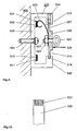
- FIG. 9 shows a second embodiment of a hanging device according to the invention.
- the profile part 500 the fastening unit is similar to that shown in Figs. 6 to 8, d. H. it is with his back secured by a screw 504 to a wall 306 and has at its front a Through opening 510, which also serves to attach the screw 504.
- the profile 500 can be made of metal or plastic and is substantially symmetrical with respect to a the screw 504 extending median plane.
- On the inside of the back wall of the profile 500 are a upper bus bar 501 and a lower bus bar 511 provided by means of insulation 502 and 512 are insulated from the profile part 500 and which are also symmetrical with respect to the median plane are arranged.
- the back wall 503 of the profile 500 is at regular intervals with holes for the Provided screws 504.
- the boundary edges of the opening 510 are each with a in the Longitudinal section of the profile 500 extending slot 513 and 514 provided.
- the fastener 528 comprises a preferably electrically insulating body 530 having two protrusions 527 and 526, respectively in the hinged state of the fastener 528 in the slots 513 and 514 engage and thereby guide the suspended fastener 528 in Provide profile longitudinal direction.
- a safety lock or a locking screw 524 is provided to lock the fastener 528.
- the insertion of the fastener 528 in the slot is done by first the Locking screw 524 is released upward.
- the slots 513 and 514 are dimensioned so that the Fastener 528 can be inserted from bottom to top in the slot 513 and then can be easily pivoted backwards so that it can be inserted down into the slot 514 can. Thereafter, the locking screw 524 can be screwed in again, so that the Fastener 528 is secured.
- the slots 513 and 514 have different depths to allow the fastener 528 to be symmetrical can be designed, which ensures good aesthetics and easier handling.
- a senior Screw lug 522 is passed through the body 530 and secured to the body by a nut 523 530 attached.
- the nut 523 further holds a contact spring 520, which in the position shown in Fig. 9 is in electrical contact with the upper bus bar 501 and the screw lug 522.
- the contact spring 520 is provided with contact spring slots 531 to allow for good contact with the Busbar 501 to provide.
- the bus bars 501, 511 and the contact spring 520 gilded.
- the fastener 528 is, apart from the contact spring 520, mirror-symmetrical formed with respect to an axis passing through the eyelet 522.
- the contact spring 520 is fixed connected to the body 530. Due to the symmetrical design of the profile 500, the Busbars 501, 511 and the fastener 528 may instead of the upper busbar 501 on a simple way the lower bus bar 511 be contacted with the contact spring 520 by the Whole fastener 528 rotated by 180 ° in the profile 500 and the slots 513, 514 used becomes.
- This embodiment has the advantage that only a single basic type of fasteners must be provided and the user before mounting anyway no adjustment operations must make the contact elements, but he can easily by the choice of Orientation of the fastener when hanging determine the contact configuration.
- the body 530 of the fastener 528 is preferably made of insulating material so that if necessary signals can be sent from the interior of the profile 500.
- the Fastener 528 may optionally also with an electronics and / or a battery, a Be equipped accumulator or emergency power supply.
- a bezel or bezel 529 is shown, in the slots 513, 514 of the front of the Profile 500 is used to cover the opening 510.
- the aperture 529 is preferably made made of insulating material, and may optionally with (not shown) contact springs be provided to contact the bus bars 501 and 511 and with on the aperture 529th provided (not shown) electronic devices or a battery holder to contact.
- the aperture 529 serves primarily to cover those parts of the opening 510, the not covered with a fastener 528. If the bezel with a battery holder is equipped, the battery used for an emergency power supply of the monitoring device serve in the event of failure of the regular power supply of the bus bars 501, 511.
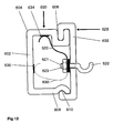
- Fig. 12 shows a third embodiment of a hanging device according to the invention, in which the Profile 600 is preferably made of plastic and secured with its back 602 to the wall 306 is.
- the top 604 of the profile 600 is provided with a slot 606, while the bottom 608 with a slot 610 is provided.
- the fastener 628 includes a body 632 and a hook 622 which has been passed through the body 632 has a thread 621 on which a nut 623 is screwed to attach the hook to the body 632. Further, the nut 623 holds one Spring 620, which contacts a bus bar 634 provided on the inside of the upper side 604.
- the body 632 is formed so that it can be suspended with its upper end in the slot 606 and with its lower end in the slot 610 can be latched.
- a second busbar 636 is provided on the inside of the back 602 .
- the spring 620 against a differently shaped spring 630 are replaced, which is shown in phantom in Fig. 12.
- the Fasteners 628 can also be provided with an exchange function Varieties of fasteners 632 are provided, each with a spring 620 or a Spring 630 are firmly connected, the determination of the contact then on the selection of the variety the fastening element 628 takes place.
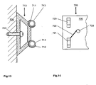
- FIGS. 13 and 14 show a fourth embodiment of a device according to the invention Hanging device that differs from the previously described embodiments in that that no rail or profile-shaped fastening unit is provided, but that the Fastening unit of a plurality of in a row on a wall 303 mounted holding elements 710 and two parallel pipe-shaped current guides 713 and 714 is formed, which are of the Retaining elements 710 are held by means of respective receivers 711 and 712.
- the current guides can be partially provided with an insulating layer.
- the pickups 711, 712 are formed so that the current guides 713, 714 are clipped can.
- FIG. 14 shows a fastening element 728 for the fastening unit illustrated in FIG. 13, which comprises a body 730 with a contact element designed as a conductive clip or hook 721 and a correspondingly symmetrical and arranged non-conductive clip or hook 720 includes as an auxiliary element.
- the contact element 721 is connected by means of a connecting conductor 722 with a Contact 723, which is passed through the body 730 and for connection to a conductive Suspension element 12A, 12A serves, is connected.
- the body 730 with the contact element 721 and the Auxiliary member 720 is formed so that the contact element 721, for example, in the lower Power guide 714 and the auxiliary member 720 can be hung in the upper power guide 713, wherein the contact element 721 then for electrical contact with the lower current guide 714 provides.
- the contact configuration can be reversed be, d. H. the contact element 721 then makes electrical contact with the upper Power guide 713. It is understood that in Fig. 14, only one half of the fastener 728th is shown, wherein the half, not shown, is constructed symmetrically to the half shown.
- fasteners for mounting units with two current paths have been described.
- the principles described also apply to fastening units with more than two Current paths are applicable, such as e.g. in the monitoring systems according to FIGS. 2 and 3.
- the fasteners may be configured to selectively one of three or four Can contact current paths (a single basic type) or it can correspond to three or four various types of fasteners may be provided.
- a Fastener simultaneously contacted two current paths and en slaughterend two connection poles having.
- a theft protection for suspended items to be monitored can also take place in that in at least one hanging element of a suspended object, a force sensor for detecting the Suspension force is integrated.
- the force sensor could also be integrated into the fastening element be, which connects the hanging element with the mounting unit.
- the sensor can be measuring signal send to the alarm unit, which then determines that an alarm case exists when a predetermined Force is exceeded, and in corresponding signal there.
- the force sensor acts as a force meter and as a transponder and is preferably on the hanging element or the hanging elements with the corresponding current paths of the mounting rail or unit for power supply from the Power source or for communication with the alarm device connected. Basically, the Sensor but also give an alarm signal itself.
- a sensor can be provided to be monitored object, the distance of the suspended object of detects the wall and provides a signal when the distance of the suspended object from the wall leaves a predetermined tolerance range.
- the senor may send its distance measurement signal to the alarm unit, which then determines if there is an alarm case.
- the power supply of the sensor and, if necessary, its communication takes place preferably in the manner described above, d. H. via conductive hanging elements.
- the sensor is as capacitive sensor or formed as an optical sensor, wherein in the latter case, preferably a Send light beam to the wall and detects the reflected light.
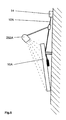
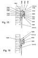
- the cable 1014A or 1014B is connected at its upper end to a fastening element 1022A or 1022B, which is suspended in the fastening unit 1016 and has a contact element 1024, which is in electrical contact with one of the current paths 1018 and 1020, respectively.
- the cables 1014A and 1014B and the fasteners 1022A and 1022B are electrically conductive so that the cable 1014A is in electrical communication with the flow path 1020 while the cable 1014B is in electrical communication with the flow path 1018.
- the attachment unit 1016 includes a first trough-shaped portion 1026 that is open-topped and includes a base 1028 and two side walls 1030 and 1032.
- the current paths 1018 and 1020 are attached to the inside of the side walls 1036 and 1032, respectively.
- the second part 1038 essentially forms an upwardly closed U-shape, while the first trough-shaped part 1026 forms a substantially upwardly open U-shape.
- the fastener 1022A or 1022B is essentially a downwardly open U-shaped member formed with a base 1044 and two legs 1046 and 1048, wherein the free end of the leg 1046 is connected to the cable 1014A and 1014B and the free end of the leg 1048 in the first trough-shaped part 1026 of the fastening unit 1016 is mounted and thereby substantially from the Base 1028 is supported.
- the leg 1048 carries on its outer side and the contact element 1024th
- the fastener 1022A or 1022B is suspended in the mounting unit 1016 by from below through the gap between the side wall 1042 of the second trough-shaped part 1038 and the side wall 1030 of the trough-shaped first part 1026 is inserted until the leg 1048 can be lifted over the upper end of the side wall 1030, whereby the fastener 1022A and 1022B can be hung in the first trough-shaped part 1026.
- the hanger of FIGS. 15 and 16 is very inexpensive to manufacture, visually appealing and easy to use.
- the fasteners 1022A and 1022B may be in the first trough-shaped Part 1026 along the attachment unit 1016 are moved freely, without the electrical Contact to the current paths 1018 or 1020 is interrupted. This allows a flexible setting the suspension point of the corresponding image 1010.
- each picture is 1010 on its back with an electronic Monitoring unit 1012 provided.
- the monitoring unit 1012 comprises a monitoring element 1050, which is designed as a transponder, and by means of connecting lines 1052 with two terminals 1054, which in turn are in electrical contact with the cable 1014A and 1014B, respectively.
- the monitoring unit 1012 comprises an elastic film 1056, with which the transponder 1050 and the connecting lines 1052 are firmly and permanently connected and which on their Rear side of an adhesive layer for adhering the monitoring unit 1012 on the back of the image 10 includes.
- the film 1056 is designed in terms of its material, its thickness and its elasticity, that it tears from the image 1010 in the attempted mechanical detachment in glued state. to To reinforce this effect, the film 1056 is provided with perforations 1058.
- Transponder 1050 and interconnect lines 1052 are preferably on foil 1056 laminated or printed or welded into the film 1056.
- the monitoring system is designed so that the control unit via the current paths 1018 and 1020 the attachment unit 1016 and the suspension cables 1014A and 1014B, respectively, with each one Transponder 1050 is in electrical connection.
- the Transponder 1050 by a resistor, each image 1010 an individual resistance value is assigned and all resistors are arranged in parallel.
- the control unit 1220 (or 20, 120) then detects the current through the through the parallel circuit formed total loop and generated in case of deviations from a predetermined setpoint Alarm signal.
- the transponder 1050 may also be designed as a digital logic unit that the corresponding image 1010 by means of a respectively assigned only once digital code value, the per digital memory, dip switches, jumpers or the like is fixed to the logic unit, identified.
- the monitoring is performed so that the control unit via the current paths 1018 and 1020, and the suspension cables 1014A and 1014B, respectively, send signals to the transponder 1050 that are sent from the be acknowledged with the specially assigned code value.
- the absence of a Acknowledgment signal leads to the control unit to generate a corresponding alarm signal. there the specially affected image can be identified.
- the alarm signal is thus triggered as soon as the electrical connection between the control unit and the transponder 1050 is interrupted in any way.
- This can e.g. be done by a Rope 1014A and 1014B, respectively.
- the corresponding fastener 1022A or 1022B, from the Fastening unit 1016 is posted or attempted, the monitoring unit 1012 as a whole from the image 1010.
- the film breaks 1056, e.g. along the perforations 1058, whereby at least one of Connection lines 1052 is interrupted or the transponder 1050 itself is damaged.
- the resulting interruption of the electrical connection between the control unit and the Transponder 1050 generates a corresponding alarm signal at the control unit.
- a comparable motion detector 1214 can with Advantage can also be integrated into a lighting unit 1210, as shown in FIG. 19.
- the control unit is designed so that it is in the absence of a specific signal from one of Transponder 1050 and / or when detecting an alarm signal from one of the motion detectors corresponding image identified.
- the control unit forms part of a monitoring system which further comprising a display device and a memory in which graphical representations of the individual images 1010 are stored.
- the control unit is designed to operate after detection of the image 1010 affected by the alarm situation, the graphic representation of the corresponding image 1010 from the memory (1224, Fig. 19) causes on the display device, so that a Supervisor can immediately recognize which image is affected.
- the graphic Representation of the affected image may display additional information, such as the Room number and an identification number assigned to the picture.
- a can general alarm by means of signal generator 1222 (FIG. 19) locally or at different locations simultaneously are given.
- surveillance cameras e.g., camera 1212 integrated into a lighting unit 1210
- the monitoring system can then be designed so that in the absence of a specific signal from the transponders 1050 and / or upon detection of an alarm signal from one of the Motion detector additionally image signals of the associated image associated with the surveillance camera be displayed on the display device.
- image signals of the affected Security camera for a certain period of time, the e.g. multiple days can amount.
- the saving can proceed in such a way that image signals for each one frame of the Security camera stored at predetermined intervals, e.g. at a distance of one Second. For example, the saved images may be overwritten after about 10 days become.
- the surveillance cameras in the Lighting elements integrated and can cover the entire area from one to be monitored Capture object.
- a serial data transmission format similar to the so-called USB standard are used, so that also several cameras on the available Power or signal conductors can be operated.
- acoustic sensors 1214 may be provided in the vicinity of the images, and when absent a specific signal from one of the transponders 1050 and / or upon detection of an alarm signal from one of the motion detector signals of the image associated with the acoustic sensor in similar to the signals of the surveillance camera recorded and temporarily be stored.
- a plurality of control units 1220 may be provided, which are connected so that they individually or in be used simultaneously, the control units e.g. via modems 1226 and associated Network connections 1228, 1230 can be interconnected to a computer network.
- a computer network can be designed as an intranet or it can have internet connections be formed.
- the monitoring system is remotely controllable, wherein the Remote control, for example by means of modem 1226 and telephone system or by means of a direct digital Network connection can be made.
- control unit can also form several connected workstations by several Display devices, e.g. in the form of so-called terminals.
- Fig. 18 which shows the rear view of an image to be suspended and monitored 1110, is a further embodiment of an electronic monitoring unit 1112 shown on the Rear of the image 1110 is attached.
- the image 1110 is hung with two ropes 1114 and 1116, respectively also as an electrical communication link between the monitoring unit 1112 and a Serving (not shown) central control unit, for example, by being electrically conductive are.
- a strain gauge 1120 is integrated, which replaces a cable section and the Load of the cable 1116 detected by the image 110.
- the monitoring unit 1112 is over terminals 1122, 1124 electrically connected to the strain gauge 1120 to a current load of the Rope 116 corresponding electrical signal to detect. Once this load signal a leaves the predetermined fluctuation range, the monitoring unit 1112 gives an alarm signal to the Control unit off, since then a theft case or the like is to be expected.
- a monitoring unit on the one hand be wired into a surveillance system, or via wireless Connection. But it can also be ensured that in addition to a first monitoring system second is provided for individual or all monitoring units, which is independent of the first works. For this purpose, it is proposed to expand the monitoring units so that they For example, inductively operating second transponder, which by an independent and mobile controlling authority in occasional and essentially incognito Control gears can be queried so that the existence and functionality of the intended Monitoring units can be verified.
Landscapes
- Physics & Mathematics (AREA)
- General Physics & Mathematics (AREA)
- Business, Economics & Management (AREA)
- Emergency Management (AREA)
- Burglar Alarm Systems (AREA)
- Emergency Alarm Devices (AREA)
- Alarm Systems (AREA)
- Spray Control Apparatus (AREA)
Description
Das Seil 1014A bzw. 1014B ist an seinem oberen Ende mit einem Befestigungselement 1022A bzw. 1022B verbunden, welches in die Befestigungseinheit 1016 eingehängt ist und ein Kontaktelement 1024 aufweist, das in elektrischem Kontakt mit einer der Strombahnen 1018 bzw. 1020 steht. Die Seile 1014A und 1014B sowie die Befestigungselemente 1022A und 1022B sind elektrisch leitend ausgebildet, so daß das Seil 1014A in elektrischer Verbindung mit der Strombahn 1020 steht, während das Seil 1014B in elektrischer Verbindung mit der Strombahn 1018 steht. Die Befestigungseinheit 1016 umfaßt einen ersten trogförmigen Teil 1026, der nach oben offen ist und eine Basis 1028 und zwei Seitenwände 1030 und 1032 umfaßt. Die von der Gebäudewand 1034 weiter entfernt liegende Seitenwand 1032 des trogförmigen ersten Teils 1026 geht nach oben in eine Seitenwand 1036 eines zweiten trogförmigen Teils 1038 über, der nach unten offen ist und neben der Seitenwand 1036 eine Basis 1040 und eine zweite Seitenwand 1042 umfaßt, die zur Anbringung der Befestigungseinheit 1016 an der Gebäudewand 1034 dient und dabei im wesentlichen an der Gebäudewand 1036 anliegt. Die Strombahnen 1018 und 1020 sind an der Innenseite der Seitenwand 1036 bzw. 1032 angebracht. Der zweite Teil 1038 bildet im wesentlichen eine nach oben geschlossene U-Form, während der erste trogförmige Teil 1026 im wesentlichen nach oben offene U-Form bildet.
Claims (25)
- Hängevorrichtung zum Aufhängen von elektrisch zu kontaktierenden Gegenständen (10A, 10B), mit einer raumfest anbringbaren langgestreckten Befestigungseinheit (300), die mindestens zwei Strombahnen (324, 326, 501, 511, 634, 636, 713, 714) aufweist, gekennzeichnet durch mindestens ein in die Befestigungseinheit einhängbares Befestigungselement (312, 528, 628, 728) für jeden aufzuhängenden Gegenstand, wobei das bzw. jedes Befestigungselement in eingehängtem Zustand entlang der Befestigungseinheit verschiebbar ist und mit mindestens einem Kontaktelement (330, 520, 620, 630, 721) versehen ist, welches unabhängig von der Verschiebung des eingehängten Befestigungselements einen elektrischen Kontakt zu einer der Strombahnen herstellt, oder wobei das bzw. jedes Befestigungselement mit mindestens einem Kontaktelement (330, 520, 620, 630, 721) versehen ist, das einen elektrischen Kontakt zu einer der Strombahnen herstellt, wobei das bzw. jedes Befestigungselement so ausgebildet ist, daß es eine Wählbarkeit gewährleistet, zu welcher der Strombahnen das mindestens eine Kontaktelement einen elektrischen Kontakt herstellt.
- Hängevorrichtung für mindestens einen jeweils an mindestens zwei Hängeelementen aufgehängten Gegenstand, mit mindestens zwei raumfest angebrachten Befestigungseinheiten zum Halten des bzw. jeden Hängeelements, einer an dem bzw. jedem Hängeelement oder dem bzw. jedem aufgehängten Gegenstand angebrachten elektrischen Einrichtung, sowie einer Stromquelle und/oder einer Steuereinheit, dadurch gekennzeichnet, daß das bzw. jedes Hängeelement so ausgebildet ist, daß es für eine elektrische Verbindung zwischen der jeweiligen elektrischen Einrichtung und der Steuereinheit und/oder der Stromquelle sorgt und daß die Hängevorrichtung als Überwachungsvorrichtung für den bzw. jeden aufgehängten Gegenstand ausgebildet ist, wobei die bzw. jede elektrische Einrichtung ein elektronisches Überwachungselement ist, das jeweils fest mit dem zu überwachenden Gegenstand verbundenen ist, und die Steuereinheit im Zusammenwirken mit dem bzw. den elektronischen Überwachungselement(en) erfaßt, ob eine Abweichung von einem vorgegeben Normalzustand des Gesamtsystems vorliegt.
- Überwachungseinheit für Gegenstände, insbesondere für mittels Hängeelementen aufgehängte Bilder oder andere Kunstgegenstände, mit mindestens zwei Anschlüssen für elektrische Zuleitungen und einem mittels Verbindungsleitungen mit den Anschlüssen elektrisch verbundenen elektronischen Überwachungselement in Form eines Kraft- oder Bruchsensors, dadurch gekennzeichnet, daß das Überwachungselement in Form einer elastischen Folie zum Ankleben an einen zu überwachenden Gegenstand vorhanden ist, welche Folie mit einer Klebeschicht versehen ist und so ausgebildet ist, daß sie beim versuchten mechanischen Ablösen in aufgeklebtem Zustand von dem zu überwachenden Gegenstand reißt, oder daß die Überwachungseinheit mit mindestens einem Überwachungselement in Form eines Kraftsensors elektrisch verbunden ist, welcher in mindestens ein Hängeelement jedes Gegenstands zum Erfassen der Hängekraft integriert ist, um ein Signal für die Belastung des Hängeelements zu erfassen, wobei die Überwachungseinheit jeweils auf der Rückseite des aufgehängten Gegenstands angebracht ist und in elektrische Kommunikationsverbindung mit einer übergeordneten zentralen Steuereinheit eines Überwachungssystems bringbar ist, weiterhin jede Überwachungseinheit so ausgebildet ist, daß sie dann, wenn das erfaßte Belastungssignal einen vorgegebenen Schwankungsbereich verläßt, ein Alarmsignal an die übergeordnete zentrale Steuereinheit abgibt.
- Überwachungssystem für Gegenstände, insbesondere für mitttels Hängeelementen und damit verbundenen Befestigungselementen an einer Befestigungseinheit oder Hängevorrichtung aufgehängte Bilder oder Kunstgegenstände, mit mindestens einer fest installierten Steuereinheit, dadurch gekennzeichnet, daß die Steuereinheit mindestens eine Anzeigeeinrichtung und einen Speicher, in welchem grafische Darstellungen der Gegenstände gespeichert sind, umfaßt und in Koinmunikationsverbindung mit Überwachungselementen, die jeweils einem Gegenstand zugeordnet sind und jeweils für das Liefern eines spezifischen Signals an die Steuereinheit ausgebildet sind, und/oder Bevegungsmeldern steht, die jeweils einem Gegenstand zugeordnet sind, wobei die Steuereinheit so ausgebildet ist, daß bei Ausbleiben eines spezifischen Signals und/oder bei Erfassen eines Alarmsignals von einem der Bewegungsmelder der zugeordnete Gegenstand identifiziert wird und eine grafische Darstellung des Gegenstands aus dem Speicher von der Anzeigeeinrichtung angezeigt wird,
wobei das Überwachungssystem wahlweise mit einer zusätzlichen Überwachungseinrichtung ausstattbar ist, welche geeignet ist, Informationen mit einem weiteren, mobilen Überwachungssystem auszutauschen. - Hängevorrichtung nach Anspruch 1, wobeidie Wählbarkeit dadurch gewährleistet ist, daß die Kontaktierung davon abhängt, in welcher Orientierung das bzw. jedes Befestigungselement (528, 728) in die Befestigungseinheit eingehängt wirdzumindest ein Befestigungselement (528, 728) im wesentlichen spiegelsymmetrisch bezüglich einer Mittelebene ausgebildet ist, oder die Befestigungseinheit im wesentlichen spiegelsymmetrisch bezüglich einer Mittelebene ausgebildet ist, oder das Befestigungselement in einer ersten Orientierung und in einer zweiten Orientierung in die Befestigungseinheit einhängbar ist, die zu einer ersten bzw. zweiten Kontaktkonfiguration führen, wobei das Befestigungselement in der zweiten Orientierung um 180° gegenüber der ersten Orientierung verdreht ist.
- Hängevorrichtung nach einem der vorhergehenden Ansprüche, dadurch gekennzeichnet, daß die Befestigungseinheit (300) schienenartig ausgebildet ist.
- Hängevorrichtung nach Anspruch 6, dadurch gekennzeichnet, daß die Befestigungseinheit ein einen Innenraum (318) teilweise umschließendes Profilteil (302, 402, 500, 600) umfaßt, wobei die Strombahnen als in dem Innenraum auf dem Profilteil angebrachte Stromschienen (324, 326, 501, 511, 634, 636) ausgebildet sind.
- Hängevorrichtung nach Anspruch 7, dadurch gekennzeichnet, daß das bzw. jedes Kontaktelement als Schleiffeder (330, 520, 620, 630) ausgebildet ist, die aufgrund ihrer Vorspannung bei eingehängtem Befestigungselement auf die entsprechende Stromschiene (324, 326, 501, 511, 634, 636) drückt.
- Hängevorrichtung nach Anspruch 6 bis 8, dadurch gekennzeichnet, daß das Profilteil (302, 402, 500) kanalförmig mit drei im wesentlichen geschlossenen Seiten (304, 503) und einer mit einer durchgehenden langgestreckten Öffnung (310, 510) versehenen Seite (308) ausgebildet ist, wobei das bzw. jedes Befestigungselement (312, 528) mittels der Öffnung in das Profilteil einhängbar ist.
- Hängevorrichtung nach Anspruch 6 bis 8, dadurch gekennzeichnet, daß das Profilteil (600) kanalförmig mit drei Seiten ausgebildet ist, wobei es mit seiner Rückseite (602) an einer Wand (306) befestigbar ist, die Vorderseite im wesentlichen offen ist und die Oberseite (604) mit einem ersten Schlitz (606) versehen ist und die Unterseite (608) mit einem zweiten Schlitz (610) versehen ist, wobei das bzw. jedes Befestigungselement (628) mit seinem oberen Ende in den ersten Schlitz einhängbar ist und mit seinem unteren Ende in den zweiten Schlitz einrastbar ist.
- Hängevorrichtung nach Anspruch 9 bis 10, dadurch gekennzeichnet, daß Blendenteile (529) vorgesehen sind, die in die Öffnung (510) bzw. die offene Seite des Profilteils (500, 600) einsetzbar sind.
- Hängevorrichtung nach Anspruch 11, dadurch gekennzeichnet, daß die Blendenteile (529) mit Kontaktelementen zur Kontaktierung der Strombahnen (501, 511, 634, 636) und mit leitend mit diesen Kontaktelementen verbundenen elektronischen Einrichtungen versehen sind.
- Hängevorrichtung nach einem der vorhergehenden Ansprüche, dadurch gekennzeichnet, daß die Befestigungseinheit mehrere in einer Reihe raumfest anzubringende Halteelemente (710) und mindestens zwei parallele rohr- oder stangenförmige Stromführungen (713, 714) umfaßt, wobei die Stromführungen von den Halteelementen gehalten werden.
- Hängevorrichtung nach einem der vorhergehenden Ansprüche, dadurch gekennzeichnet, daß es sich bei den aufzuhängenden Gegenständen (10A, 10B) um Kunstgegenstände handelt, die mit elektrischen Sicherheits- und/oder Beleuchtungseinrichtungen (150A, 150B, 250A, 250B, 2524 252B) versehen sind.
- Hängevorrichtung nach Anspruch 1, wobei die Befestigungseinheit (1016) einen ersten nach oben offenen trogförmigen schienenartigen Teil (1026) mit einer Basis (1028) und zwei Seitenwänden (1030, 1032) umfaßt und das bzw. jedes Befestigungselement (1022A, 1022B) einen nach unten offenen U-förmigen Teil mit einer Basis (1044) und zwei Schenkeln (1046, 1048) umfaßt, wobei das freie Ende des ersten Schenkels (1048) mit dem aufzuhängenden Gegenstand (1010) verbunden ist und das freie Ende des zweiten Schenkels (1046) in den ersten trogförmigen Teil (1026) der Befestigungseinheit eingehängt wird.
- Hängevorrichtung nach Anspruch 15, dadurch gekennzeichnet, daß eine (1032) der beiden Seitenwände (1030, 1032) des ersten trogförmigen Teils (1026) der Befestigungseinheit (1016) in eine erste (1036) von zwei Seitenwänden (1036, 1042) eines zweiten Teils (1038) der Befestigungseinheit übergeht, der eine oberhalb der ersten Seitenwand liegende und mit dieser verbundene Basis (1040) umfaßt, und die zweite Seitenwand (1042) des zweiten Teils zur Anbringung an einer Gebäudewand (1034) dient und dabei an dieser im wesentlichen anliegt, wobei der erste trogförmige Teil an der zur Gebäudewand hin gerichteten Seite der ersten Seitenwand des zweiten Teils angeordnet ist.
- Hängevorrichtung nach einem der vorhergehenden Ansprüche, dadurch gekennzeichnet, dass das bzw. jedes Hängeelement als Seil oder als Kette ausgebildet ist.
- Überwachungseinheit nach Anspruch 3, dadurch gekennzeichnet, daß das Überwachungselement (1050) ein elektrischer Schaltkreis ist, der zusammen mit den Verbindungsleitungen (1052) auf die Folie (1056) aufkaschiert ist.
- Überwachungssystem nach Anspruch 4, dadurch gekennzeichnet, daß die Identifikation der zugeordneten Gegenstände anhand einer Raumnummer oder anhand einer jedem Gegenstand (1010) zugeordneten Identifikationsnummer erfolgt.
- Überwachungssystem nach Anspruch 4 oder 19, dadurch gekennzeichnet, daß es sich bei den Gegenständen (1010) um ausgestellte Kunstgegenstände handelt.
- Überwachungssystem nach Anspruch 19 bis 20, dadurch gekennzeichnet, daß mindestens eine Überwachungskamera für die betreffenden Gegenstände (1010) vorgesehen ist.
- Überwachungssystem nach Anspruch 21, dadurch gekennzeichnet, daß bei Ausbleiben eines spezifischen Signals und/oder bei Erfassen eines Alarmsignals von einem der Bewegungsmelder Bildsignale der dem betroffenen Gegenstand (1010) zugeordneten Überwachungskamera zusätzlich auf der Anzeigeeinrichtung angezeigt werden.
- Überwachungssystem nach Anspruch 22, dadurch gekennzeichnet, daß bei Ausbleiben eines spezifischen Signals und/oder bei Erfassen eines Alarmsignals von einem der Bewegungsmelder Bildsignale der dem betroffenen Gegenstand (1010) zugeordneten Überwachungskamera für einen bestimmten Zeitraum gespeichert werden.
- Überwachungssystem nach Anspruch 19 bis 23, dadurch gekennzeichnet, daß mehrere Steuereinheiten vorgesehen sind, die so verschaltet sind, daß sie einzeln oder gleichzeitig benutzbar sind.
- Überwachungssystem nach Anspruch 24, dadurch gekennzeichnet, daß die Steuereinheiten zu einem Rechner-Netzwerk zusammengeschaltet sind.
Applications Claiming Priority (6)
| Application Number | Priority Date | Filing Date | Title |
|---|---|---|---|
| DE19855201 | 1998-11-30 | ||
| DE1998155201 DE19855201A1 (de) | 1998-11-30 | 1998-11-30 | Hängevorrichtung für Gegenstände |
| DE29906910U DE29906910U1 (de) | 1999-04-16 | 1999-04-16 | Hängevorrichtung für elektrisch zu kontaktierende Gegenstände |
| DE29906910U | 1999-04-16 | ||
| DE29910440U | 1999-06-15 | ||
| DE29910440U DE29910440U1 (de) | 1999-06-15 | 1999-06-15 | Überwachungssystem |
Publications (3)
| Publication Number | Publication Date |
|---|---|
| EP1008971A2 EP1008971A2 (de) | 2000-06-14 |
| EP1008971A3 EP1008971A3 (de) | 2001-05-09 |
| EP1008971B1 true EP1008971B1 (de) | 2005-09-28 |
Family
ID=27218838
Family Applications (1)
| Application Number | Title | Priority Date | Filing Date |
|---|---|---|---|
| EP99123612A Expired - Lifetime EP1008971B1 (de) | 1998-11-30 | 1999-11-26 | Überwachungssystem, basierend auf einer Hängevorrichtung für elektrisch zu kontaktierende Gegenstände |
Country Status (4)
| Country | Link |
|---|---|
| US (1) | US6686841B1 (de) |
| EP (1) | EP1008971B1 (de) |
| AT (1) | ATE305649T1 (de) |
| DE (1) | DE59912599D1 (de) |
Cited By (1)
| Publication number | Priority date | Publication date | Assignee | Title |
|---|---|---|---|---|
| DE202013101213U1 (de) | 2013-03-21 | 2013-05-06 | Technische Hochschule Wildau | Anordnung zum Überwachen eines Objekts |
Families Citing this family (17)
| Publication number | Priority date | Publication date | Assignee | Title |
|---|---|---|---|---|
| IL135730A (en) * | 2000-04-18 | 2004-05-12 | Visonic Ltd | Displacement sensor |
| DE10212232A1 (de) * | 2002-03-19 | 2003-10-09 | Semperlux Ag | Stromschiene mit Datenleitung |
| DE10311325A1 (de) * | 2003-03-14 | 2004-10-07 | Siemens Ag | Notfallbedienmittel für eine technische Einrichtung |
| US7026934B2 (en) * | 2003-10-31 | 2006-04-11 | Sensormatic Electronics Corporation | Method and apparatus to prevent unauthorized removal of a pedestal from a base |
| US20050223830A1 (en) * | 2004-04-09 | 2005-10-13 | Epo Science & Technology Inc. | Structure of guide spring sheet for traverse |
| US20100076701A1 (en) * | 2004-04-09 | 2010-03-25 | Loadstar Sensors, Inc. | Resistive force sensing device and method with an advanced communication interface |
| US7619519B2 (en) * | 2005-09-23 | 2009-11-17 | Richter Robert S | Alarm module for protecting wall-hung objects from tamper or theft |
| US7468665B2 (en) * | 2006-06-13 | 2008-12-23 | Motorola, Inc. | Article holder with notification mechanism |
| US7528717B2 (en) * | 2006-06-14 | 2009-05-05 | Honeywell International Inc. | Tamper detection mechanism for blind installation of circular sensors |
| US7847692B2 (en) * | 2007-10-26 | 2010-12-07 | Carmen Schuller | Anti-thief device |
| US8773266B2 (en) * | 2007-11-16 | 2014-07-08 | Intermec Ip Corp. | RFID tag reader station with image capabilities |
| WO2011079968A2 (de) * | 2009-12-29 | 2011-07-07 | Harald Ruediger | Überwachungseinrichtung für spannungslos geschaltete fahrleitungsanlagen oder freileitungen |
| DE102010048950A1 (de) | 2010-10-19 | 2012-04-19 | Airbus Operations Gmbh | Diagnosesystem und Diagnoseverfahren, Gehäusebauteil eines Schmiermittelbehälters |
| US9188487B2 (en) | 2011-11-16 | 2015-11-17 | Tyco Fire & Security Gmbh | Motion detection systems and methodologies |
| CN105227928A (zh) * | 2015-10-15 | 2016-01-06 | 上海交通大学 | 一种基于视频传感器网络的动态目标监测系统 |
| US9820398B1 (en) * | 2016-10-06 | 2017-11-14 | David R. Hall | Modular domestic appliance with electrically conductive members |
| DE102020131626A1 (de) * | 2020-11-30 | 2022-06-02 | Zumtobel Lighting Gmbh | Nutzung von leitungen eines lichtbandsystems für datenkommunikation |
Family Cites Families (11)
| Publication number | Priority date | Publication date | Assignee | Title |
|---|---|---|---|---|
| CH481434A (de) * | 1968-07-03 | 1969-11-15 | Cerberus Ag Werk Fuer Elektron | Elektrische Vorrichtung zum Schutz an einer Wand oder Raumdecke aufgehängter oder auf einem Sockel oder in einer Vitrine aufgestellter beweglicher Gegenstände gegen Diebstahl oder Beschädigung |
| US4337462A (en) | 1977-12-27 | 1982-06-29 | Lemelson Jerome H | Theft detection system and method |
| US5210846B1 (en) | 1989-05-15 | 1999-06-29 | Dallas Semiconductor | One-wire bus architecture |
| US5226137A (en) | 1989-05-15 | 1993-07-06 | Dallas Semiconductor Corp. | Electronic key with multiple password protected sub-keys using address and translation to implement a block data move between public and protected sub-keys |
| US6122704A (en) | 1989-05-15 | 2000-09-19 | Dallas Semiconductor Corp. | Integrated circuit for identifying an item via a serial port |
| US5258743A (en) * | 1991-07-29 | 1993-11-02 | Uniplex Corporation | Piezoelectric motion sensor |
| US5561417A (en) * | 1993-12-28 | 1996-10-01 | Protex International Corp. | Security device for merchandise and the like |
| WO1997004414A2 (en) | 1995-07-20 | 1997-02-06 | Dallas Semiconductor Corporation | An electronic micro identification circuit that is inherently bonded to a someone or something |
| DE29702473U1 (de) | 1997-02-13 | 1997-06-12 | Conradi, Wolfgang, 61476 Kronberg | Sicherung für Bilder |
| DE59801977D1 (de) * | 1997-06-04 | 2001-12-06 | Ascom Systec Ag Maegenwil | Verfahren zum überwachen eines vorgegebenen überwachungsbereiches |
| DE19824587A1 (de) * | 1998-06-02 | 1998-12-03 | Markus Huber | Kommunizierendes Navigationssystem |
-
1999
- 1999-11-26 DE DE59912599T patent/DE59912599D1/de not_active Expired - Lifetime
- 1999-11-26 AT AT99123612T patent/ATE305649T1/de not_active IP Right Cessation
- 1999-11-26 EP EP99123612A patent/EP1008971B1/de not_active Expired - Lifetime
- 1999-11-30 US US09/450,513 patent/US6686841B1/en not_active Expired - Lifetime
Cited By (1)
| Publication number | Priority date | Publication date | Assignee | Title |
|---|---|---|---|---|
| DE202013101213U1 (de) | 2013-03-21 | 2013-05-06 | Technische Hochschule Wildau | Anordnung zum Überwachen eines Objekts |
Also Published As
| Publication number | Publication date |
|---|---|
| EP1008971A3 (de) | 2001-05-09 |
| US6686841B1 (en) | 2004-02-03 |
| DE59912599D1 (de) | 2005-11-03 |
| EP1008971A2 (de) | 2000-06-14 |
| ATE305649T1 (de) | 2005-10-15 |
Similar Documents
| Publication | Publication Date | Title |
|---|---|---|
| EP1349437B1 (de) | Stromschiene mit Datenleitung | |
| EP1008971A2 (de) | Überwachungssystem, basierend auf einer Hängevorrichtung für elektrisch zu kontaktierende Gegenstände | |
| EP1586080B1 (de) | Verfahren und vorrichtungen zur sicherung einer ware gegen diebstahl | |
| DE1931308C3 (de) | Elektrische Vorrichtung zum Schutz beweglicher Gegenstände | |
| DE202015103728U1 (de) | Antriebssystem für ein Tor | |
| DE10249460A1 (de) | Halteteil zur Warensicherung | |
| WO1990000786A1 (de) | Anzeigeeinrichtung für feuerlöscher | |
| DE4422308C2 (de) | Automatisches Rottenwarngerät | |
| DE69114682T2 (de) | Elektrisches Kontroll- und Steuerungssystem einer Funktionseinheit, insbesondere eines Hauses eines Gebäudes, eines Schiffes oder dergleichen. | |
| EP2160033A1 (de) | Videosprechanlage mit einer Aussenstation, welche Personen mittels einer Kamera erfasst | |
| DE19524756C2 (de) | Anzeigetableau und Verfahren zu dessen Betrieb | |
| DE29906910U1 (de) | Hängevorrichtung für elektrisch zu kontaktierende Gegenstände | |
| DE102007006205B4 (de) | Unterputz-Installationsgerät | |
| DE19930329C2 (de) | Anordnung zum Einstellen und Bedienen von festinstallierten Schaltsignalgebern | |
| DE19855201A1 (de) | Hängevorrichtung für Gegenstände | |
| DE69507645T2 (de) | System zur kommunikation zwischen einer behinderten person und ihrer umgebung | |
| EP0819290B1 (de) | Diebstahlsicherungsvorrichtung | |
| DE29624301U1 (de) | Diebstahlsicherungsvorrichtung | |
| EP3792891A1 (de) | Bewegungsmelder | |
| DE19944843B4 (de) | Alarmsystem | |
| DE29602412U1 (de) | Diebstahlsicherungsvorrichtung | |
| DE29611601U1 (de) | Drahtlose Gefahrenmeldeanlage mit Fernalarmierung | |
| DE102009005521A1 (de) | Abschlussprofil | |
| DE2844428A1 (de) | Garagenpark-signalanlage | |
| DE102006028866A1 (de) | Befestigungsvorrichtung |
Legal Events
| Date | Code | Title | Description |
|---|---|---|---|
| PUAI | Public reference made under article 153(3) epc to a published international application that has entered the european phase |
Free format text: ORIGINAL CODE: 0009012 |
|
| AK | Designated contracting states |
Kind code of ref document: A2 Designated state(s): AT BE CH CY DE DK ES FI FR GB GR IE IT LI LU MC NL PT SE |
|
| AX | Request for extension of the european patent |
Free format text: AL;LT;LV;MK;RO;SI |
|
| PUAL | Search report despatched |
Free format text: ORIGINAL CODE: 0009013 |
|
| AK | Designated contracting states |
Kind code of ref document: A3 Designated state(s): AT BE CH CY DE DK ES FI FR GB GR IE IT LI LU MC NL PT SE |
|
| AX | Request for extension of the european patent |
Free format text: AL;LT;LV;MK;RO;SI |
|
| 17P | Request for examination filed |
Effective date: 20010614 |
|
| AKX | Designation fees paid |
Free format text: AT BE CH CY DE DK ES FI FR GB GR IE IT LI LU MC NL PT SE |
|
| 17Q | First examination report despatched |
Effective date: 20030224 |
|
| GRAP | Despatch of communication of intention to grant a patent |
Free format text: ORIGINAL CODE: EPIDOSNIGR1 |
|
| GRAS | Grant fee paid |
Free format text: ORIGINAL CODE: EPIDOSNIGR3 |
|
| GRAA | (expected) grant |
Free format text: ORIGINAL CODE: 0009210 |
|
| AK | Designated contracting states |
Kind code of ref document: B1 Designated state(s): AT BE CH CY DE DK ES FI FR GB GR IE IT LI LU MC NL PT SE |
|
| PG25 | Lapsed in a contracting state [announced via postgrant information from national office to epo] |
Ref country code: NL Free format text: LAPSE BECAUSE OF FAILURE TO SUBMIT A TRANSLATION OF THE DESCRIPTION OR TO PAY THE FEE WITHIN THE PRESCRIBED TIME-LIMIT Effective date: 20050928 Ref country code: IT Free format text: LAPSE BECAUSE OF FAILURE TO SUBMIT A TRANSLATION OF THE DESCRIPTION OR TO PAY THE FEE WITHIN THE PRESCRIBED TIME-LIMIT;WARNING: LAPSES OF ITALIAN PATENTS WITH EFFECTIVE DATE BEFORE 2007 MAY HAVE OCCURRED AT ANY TIME BEFORE 2007. THE CORRECT EFFECTIVE DATE MAY BE DIFFERENT FROM THE ONE RECORDED. Effective date: 20050928 Ref country code: IE Free format text: LAPSE BECAUSE OF FAILURE TO SUBMIT A TRANSLATION OF THE DESCRIPTION OR TO PAY THE FEE WITHIN THE PRESCRIBED TIME-LIMIT Effective date: 20050928 Ref country code: FI Free format text: LAPSE BECAUSE OF FAILURE TO SUBMIT A TRANSLATION OF THE DESCRIPTION OR TO PAY THE FEE WITHIN THE PRESCRIBED TIME-LIMIT Effective date: 20050928 |
|
| REG | Reference to a national code |
Ref country code: GB Ref legal event code: FG4D Free format text: NOT ENGLISH |
|
| REG | Reference to a national code |
Ref country code: CH Ref legal event code: EP |
|
| REG | Reference to a national code |
Ref country code: IE Ref legal event code: FG4D Free format text: LANGUAGE OF EP DOCUMENT: GERMAN |
|
| REF | Corresponds to: |
Ref document number: 59912599 Country of ref document: DE Date of ref document: 20051103 Kind code of ref document: P |
|
| PG25 | Lapsed in a contracting state [announced via postgrant information from national office to epo] |
Ref country code: CY Free format text: LAPSE BECAUSE OF FAILURE TO SUBMIT A TRANSLATION OF THE DESCRIPTION OR TO PAY THE FEE WITHIN THE PRESCRIBED TIME-LIMIT Effective date: 20051126 Ref country code: AT Free format text: LAPSE BECAUSE OF NON-PAYMENT OF DUE FEES Effective date: 20051126 |
|
| PG25 | Lapsed in a contracting state [announced via postgrant information from national office to epo] |
Ref country code: MC Free format text: LAPSE BECAUSE OF NON-PAYMENT OF DUE FEES Effective date: 20051130 Ref country code: LU Free format text: LAPSE BECAUSE OF NON-PAYMENT OF DUE FEES Effective date: 20051130 Ref country code: LI Free format text: LAPSE BECAUSE OF NON-PAYMENT OF DUE FEES Effective date: 20051130 Ref country code: CH Free format text: LAPSE BECAUSE OF NON-PAYMENT OF DUE FEES Effective date: 20051130 |
|
| PG25 | Lapsed in a contracting state [announced via postgrant information from national office to epo] |
Ref country code: SE Free format text: LAPSE BECAUSE OF FAILURE TO SUBMIT A TRANSLATION OF THE DESCRIPTION OR TO PAY THE FEE WITHIN THE PRESCRIBED TIME-LIMIT Effective date: 20051228 Ref country code: GR Free format text: LAPSE BECAUSE OF FAILURE TO SUBMIT A TRANSLATION OF THE DESCRIPTION OR TO PAY THE FEE WITHIN THE PRESCRIBED TIME-LIMIT Effective date: 20051228 Ref country code: DK Free format text: LAPSE BECAUSE OF FAILURE TO SUBMIT A TRANSLATION OF THE DESCRIPTION OR TO PAY THE FEE WITHIN THE PRESCRIBED TIME-LIMIT Effective date: 20051228 |
|
| PG25 | Lapsed in a contracting state [announced via postgrant information from national office to epo] |
Ref country code: ES Free format text: LAPSE BECAUSE OF FAILURE TO SUBMIT A TRANSLATION OF THE DESCRIPTION OR TO PAY THE FEE WITHIN THE PRESCRIBED TIME-LIMIT Effective date: 20060108 |
|
| GBT | Gb: translation of ep patent filed (gb section 77(6)(a)/1977) |
Effective date: 20060117 |
|
| PG25 | Lapsed in a contracting state [announced via postgrant information from national office to epo] |
Ref country code: PT Free format text: LAPSE BECAUSE OF FAILURE TO SUBMIT A TRANSLATION OF THE DESCRIPTION OR TO PAY THE FEE WITHIN THE PRESCRIBED TIME-LIMIT Effective date: 20060228 |
|
| NLV1 | Nl: lapsed or annulled due to failure to fulfill the requirements of art. 29p and 29m of the patents act | ||
| PGFP | Annual fee paid to national office [announced via postgrant information from national office to epo] |
Ref country code: BE Payment date: 20060426 Year of fee payment: 7 |
|
| REG | Reference to a national code |
Ref country code: IE Ref legal event code: FD4D |
|
| ET | Fr: translation filed | ||
| REG | Reference to a national code |
Ref country code: CH Ref legal event code: PL |
|
| PLBE | No opposition filed within time limit |
Free format text: ORIGINAL CODE: 0009261 |
|
| STAA | Information on the status of an ep patent application or granted ep patent |
Free format text: STATUS: NO OPPOSITION FILED WITHIN TIME LIMIT |
|
| 26N | No opposition filed |
Effective date: 20060629 |
|
| PG25 | Lapsed in a contracting state [announced via postgrant information from national office to epo] |
Ref country code: BE Free format text: LAPSE BECAUSE OF NON-PAYMENT OF DUE FEES Effective date: 20061130 |
|
| BERE | Be: lapsed |
Owner name: PRUFTECHNIK DIETER BUSCH A.G. Effective date: 20061130 |
|
| REG | Reference to a national code |
Ref country code: FR Ref legal event code: PLFP Year of fee payment: 17 |
|
| REG | Reference to a national code |
Ref country code: FR Ref legal event code: PLFP Year of fee payment: 18 |
|
| REG | Reference to a national code |
Ref country code: FR Ref legal event code: PLFP Year of fee payment: 19 |
|
| PGFP | Annual fee paid to national office [announced via postgrant information from national office to epo] |
Ref country code: DE Payment date: 20181122 Year of fee payment: 20 |
|
| PGFP | Annual fee paid to national office [announced via postgrant information from national office to epo] |
Ref country code: GB Payment date: 20181126 Year of fee payment: 20 Ref country code: FR Payment date: 20181127 Year of fee payment: 20 |
|
| REG | Reference to a national code |
Ref country code: DE Ref legal event code: R081 Ref document number: 59912599 Country of ref document: DE Owner name: PRUEFTECHNIK DIETER BUSCH GMBH, DE Free format text: FORMER OWNER: PRUEFTECHNIK DIETER BUSCH AG, 85737 ISMANING, DE |
|
| REG | Reference to a national code |
Ref country code: DE Ref legal event code: R071 Ref document number: 59912599 Country of ref document: DE |
|
| REG | Reference to a national code |
Ref country code: GB Ref legal event code: PE20 Expiry date: 20191125 |
|
| PG25 | Lapsed in a contracting state [announced via postgrant information from national office to epo] |
Ref country code: GB Free format text: LAPSE BECAUSE OF EXPIRATION OF PROTECTION Effective date: 20191125 |