EP1009064A2 - Connecteur électrique - Google Patents
Connecteur électrique Download PDFInfo
- Publication number
- EP1009064A2 EP1009064A2 EP99124659A EP99124659A EP1009064A2 EP 1009064 A2 EP1009064 A2 EP 1009064A2 EP 99124659 A EP99124659 A EP 99124659A EP 99124659 A EP99124659 A EP 99124659A EP 1009064 A2 EP1009064 A2 EP 1009064A2
- Authority
- EP
- European Patent Office
- Prior art keywords
- plug
- housing
- coding
- receiving
- contact
- Prior art date
- Legal status (The legal status is an assumption and is not a legal conclusion. Google has not performed a legal analysis and makes no representation as to the accuracy of the status listed.)
- Granted
Links
Images


Classifications
-
- H—ELECTRICITY
- H01—ELECTRIC ELEMENTS
- H01R—ELECTRICALLY-CONDUCTIVE CONNECTIONS; STRUCTURAL ASSOCIATIONS OF A PLURALITY OF MUTUALLY-INSULATED ELECTRICAL CONNECTING ELEMENTS; COUPLING DEVICES; CURRENT COLLECTORS
- H01R13/00—Details of coupling devices of the kinds covered by groups H01R12/70 or H01R24/00 - H01R33/00
- H01R13/46—Bases; Cases
- H01R13/502—Bases; Cases composed of different pieces
- H01R13/506—Bases; Cases composed of different pieces assembled by snap action of the parts
-
- H—ELECTRICITY
- H01—ELECTRIC ELEMENTS
- H01R—ELECTRICALLY-CONDUCTIVE CONNECTIONS; STRUCTURAL ASSOCIATIONS OF A PLURALITY OF MUTUALLY-INSULATED ELECTRICAL CONNECTING ELEMENTS; COUPLING DEVICES; CURRENT COLLECTORS
- H01R13/00—Details of coupling devices of the kinds covered by groups H01R12/70 or H01R24/00 - H01R33/00
- H01R13/64—Means for preventing incorrect coupling
Definitions
- the invention relates to an electrical connector for a number of plug contacts in a compact design, consisting of a plug and a device side Power strip with a plug-in collar for receiving the Plug, in which the connector housing for receiving Plug contact housings are designed, each several Take in plug contact elements and in the connector housing can be locked,
- Connectors of this type are, for example, by the reference DE 4330626 C2 known.
- This as an outer casing designated connector housing has a designated as insertion channel Receiving shaft for two designated as contact carriers Different width plug contact housings.
- the insertion channel is open on the front of the outer case.
- Special Measures to lock the contact carriers in the insertion channel provided on its back which is a relatively complex Tool concept required.
- Special assignment safeguards in Form of coding measures between the insertion channel and the contact carriers to be accommodated therein are not necessary here, since there is only one insertion channel.
- the two to be addressed as a contact carrier package wide contact carriers can also take into account the So-called secondary fuse usually provided for the socket contacts housed in the contact carriers are not inserted at all into the insertion channel, if they are not arranged correctly next to each other.
- Such electrical connectors also include connector housings conceivable, in which each plug contact housing a receiving shaft assigned. Here it may be necessary to secure the mapping also between the plug contact housings and to provide the receiving shafts of the connector housing. At compact design, it is not possible in this case from coding bars or coding grooves running in the direction of insertion on the outer sides of the side walls of the plug contact housing or the inside of the side walls of the receiving shafts To make use of.
- the invention has for its object a new compact Design for an electrical connector with a two and more slots for plug-in contact housings Specify the connector housing with an inexpensive tool concept also a coding between the receiving shafts and makes the plug contact housings possible.
- the connector housing having several identical dimensions Has receiving shafts which are arranged side by side and receiving openings on the front of the connector housing have that the plug contact housing in its width and depth to the dimensions of the receiving shafts of the connector housing are adapted for coding between the receiving shafts of the connector housing and the plug contact housings on the one hand, the rear wall of the connector housing in the area of each Receiving shaft and on the other hand the rear wall of each plug contact housing Coding elements in the form of depressions and Has increases when inserting the plug contact housing in the receiving shafts of the connector housing in pairs interlock and that the depth and / or height dimensions of the interlocking coding elements is chosen so that the latching of a plug contact housing in a receiving slot of the connector housing is only possible if the encoding of the receiving slot with the coding of the plug contact housing to be included here matches.
- the connector housing 2 has two of the same Receiving shafts 3 for two identical plug contact housings 4 shown in FIG. 2.
- the receiving shafts 3 have their receiving openings 5 on the front side 6 of the connector housing 2.
- Between the receiving shafts 3 there is a narrow wall receiving slot 7, which is in the lower and middle area of the Plug housing 2 has an opening 8 on its front 6 and an opening 9 in its rear wall 10.
- the wall-receiving shaft 7 has a continuous opening 11 in the bottom 12 of the connector housing 2.
- the bottom 12 of the connector housing 2 has in the area of the receiving shafts 3 plug openings 13 for not in the drawing Plug contacts shown, which are in working condition of the plug 1 in the vertical receiving channels 14 of the Plug contact housing 4 are used. If the plug contact housing 4 until it snaps into place to be described is inserted into the receiving shafts 3 of the connector housing 2 are aligned in the receiving channels 14 of the Plug contact housing 4 plug contacts used, preferably Socket contacts, with the plug openings 13 in the bottom 12 the connector housing 2.
- Plug contact housing 4 in the functional state of the plug 1 inserted plug contacts have the plug contact housing 4 in the central area on the outer sides 15 of their a horizontal groove-like recess 17 on both side walls 16 on, which in its extension only through the front wall 18 the plug contact housing 4 is limited and in depth extend into the receiving channels 14 of the plug contact housing 4.
- these groove-like recesses 17 reach Push the plug contact housing 4 into the receiving shafts 3 safety strips 19 running in the insertion direction with hook-shaped cross-section, which in the middle area the inner sides 20 of the side walls 21 of the receiving shafts 3 are molded.
- locking teeth 24 are formed in the upper and lower region.
- the locking teeth 24 are in the upper and lower areas 3 counter-locking openings in the side walls 21 of the receiving shafts 25 assigned, in which the plug contact housing 4 in snap into the receiving slots 3 when inserted.
- the locking teeth 24 engage behind the front edge 26 of the Counter-locking openings 25.
- the correct assignment guaranteed by coding the plug contact housing 4 to the receiving shafts 3 of the Plug housing 2 is provided on its rear wall 10.
- the rear wall 10 of the connector housing 2 in the central region its receiving shafts 3 vertically one above the other two identical coding elements 27 in the form of horizontal ones Longitudinal holes 28 of rectangular shape.
- corresponding Ways are on the outer sides 29 of the rear walls 30 of the Plug contact housing 4, see Fig. 2, vertically in the central area one above the other two of the same, to the coding elements 27 complementary coding elements 31 in the form of horizontally aligned short longitudinal webs 32 formed.
- the end faces 33 of the longitudinal webs 32 are folded.
- the plug contact housing 4 At the Push the plug contact housing 4 into the receiving shafts 3 of the connector housing 2 engage the coding elements 27 and 31 only interlocking if they are in relation to each other their position coincide with each other.
- the high of Longitudinal webs 32 are defined so that the plug contact housing 4 not in the Allow slots 3 to snap into place.
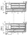
- the connector housing 2 At its top is the connector housing 2 with a cover 34 provided in the area of the receiving shafts 3 for Front 6 of the connector housing 2 open rounded recesses 35 has. These recesses 35 are for the cable connections of the plug contacts in the receiving channels 14 of the Plug contact housing 4 provided.
- the receiving shafts 3 of the connector housing 2 are higher than the plug contact housing 4, so that with plug-in contact housings pushed into the receiving shafts 3 4, as can be clearly seen in FIG. 3, in the upper region the receiving shafts 3 each one to the front 6 of the connector housing 2 open cable connection space 36 available is.
- the embodiment shown in the drawing for the Plug 1 of an electrical connector is for his Plug connection in a device-side connector strip for designed and locked into the connector strip
- an assignment lock for the plug connection in the form of a coding.
- a detent spring 37 on the side of the rear wall 10 at the bottom 12 of the connector housing 2 is formed and parallel to the rear wall 10 extends to the upper edge of the connector housing 2.
- the cover 34 has one over the rear wall 10 of the plug housing 2 extending collar 38 on, in which the detent spring 37 protrudes with its free end.
Landscapes
- Connector Housings Or Holding Contact Members (AREA)
- Details Of Connecting Devices For Male And Female Coupling (AREA)
Applications Claiming Priority (2)
| Application Number | Priority Date | Filing Date | Title |
|---|---|---|---|
| DE19857325 | 1998-12-11 | ||
| DE19857325 | 1998-12-11 |
Publications (3)
| Publication Number | Publication Date |
|---|---|
| EP1009064A2 true EP1009064A2 (fr) | 2000-06-14 |
| EP1009064A3 EP1009064A3 (fr) | 2001-05-09 |
| EP1009064B1 EP1009064B1 (fr) | 2003-11-26 |
Family
ID=7890828
Family Applications (1)
| Application Number | Title | Priority Date | Filing Date |
|---|---|---|---|
| EP99124659A Expired - Lifetime EP1009064B1 (fr) | 1998-12-11 | 1999-12-10 | Connecteur électrique |
Country Status (4)
| Country | Link |
|---|---|
| EP (1) | EP1009064B1 (fr) |
| AT (1) | ATE255287T1 (fr) |
| DE (1) | DE59907855D1 (fr) |
| ES (1) | ES2210952T3 (fr) |
Cited By (1)
| Publication number | Priority date | Publication date | Assignee | Title |
|---|---|---|---|---|
| DE102008045129A1 (de) * | 2008-09-01 | 2010-03-04 | Tyco Electronics Amp Gmbh | Steckverbinder mit modularem Aufbau |
Family Cites Families (2)
| Publication number | Priority date | Publication date | Assignee | Title |
|---|---|---|---|---|
| DE4441281C2 (de) * | 1994-11-19 | 1997-11-06 | Grote & Hartmann | Steckverbinder |
| DE19652855C1 (de) * | 1996-12-18 | 1998-01-29 | Siemens Ag | Elektrischer Steckverbinder |
-
1999
- 1999-12-10 AT AT99124659T patent/ATE255287T1/de not_active IP Right Cessation
- 1999-12-10 EP EP99124659A patent/EP1009064B1/fr not_active Expired - Lifetime
- 1999-12-10 DE DE59907855T patent/DE59907855D1/de not_active Expired - Fee Related
- 1999-12-10 ES ES99124659T patent/ES2210952T3/es not_active Expired - Lifetime
Cited By (2)
| Publication number | Priority date | Publication date | Assignee | Title |
|---|---|---|---|---|
| DE102008045129A1 (de) * | 2008-09-01 | 2010-03-04 | Tyco Electronics Amp Gmbh | Steckverbinder mit modularem Aufbau |
| DE102008045129B4 (de) * | 2008-09-01 | 2010-04-15 | Tyco Electronics Amp Gmbh | Steckverbinder mit modularem Aufbau |
Also Published As
| Publication number | Publication date |
|---|---|
| DE59907855D1 (de) | 2004-01-08 |
| ATE255287T1 (de) | 2003-12-15 |
| EP1009064A3 (fr) | 2001-05-09 |
| EP1009064B1 (fr) | 2003-11-26 |
| ES2210952T3 (es) | 2004-07-01 |
Similar Documents
| Publication | Publication Date | Title |
|---|---|---|
| EP1067636B1 (fr) | Connecteur électrique | |
| DE19916865C2 (de) | Elektrischer Buchsenkontakt mit einem separaten Federteil | |
| DE3345128C2 (fr) | ||
| DE19717984A1 (de) | Quer zur seiner Längserstreckung und aus zwei Richtungen in den Verbindungszustand bringbarer elektrischer Verbinder | |
| DE1465225A1 (de) | Elektrische Flachsteckkupplung | |
| DE3537722A1 (de) | Elektrischer stecker | |
| DE2338778B2 (de) | Buchsenleiste | |
| EP0831559A2 (fr) | Connecteur à fiche | |
| DE19638368A1 (de) | Steckverbinder | |
| DE19532623B4 (de) | Elektrischer Stecker mit einem Betätigungsschieber | |
| EP0831561A2 (fr) | Assemblage de connecteurs électriques | |
| EP1009064B1 (fr) | Connecteur électrique | |
| DE2802643C2 (fr) | ||
| EP0627130B1 (fr) | Connecteur enfichable | |
| DE10243313B4 (de) | Kodierbarer Steckverbinder | |
| DE69411480T2 (de) | Anschlussleiste | |
| DE19624646C2 (de) | Steckverbinder | |
| DE19739503C2 (de) | Elektrischer Steckverbinder | |
| EP0527332B1 (fr) | Prise feuille avec moyens de guidage à ressort en un seule piece | |
| DE202008014441U1 (de) | Steckverbinder | |
| DE19652855C1 (de) | Elektrischer Steckverbinder | |
| DE19814401B4 (de) | Elektrischer Kontakt zur Kontaktierung eines zylindrischen komplementären Kontaktstiftes und entsprechende elektrische Steckverbinder | |
| DE10019825B4 (de) | Elektrischer Steckverbinder | |
| DE8621150U1 (de) | Elektrischer Vielfachanschluß-Verbinder | |
| DE3625927C2 (de) | Rahmen zur Aufnahme und Halterung von Schaltelementen |
Legal Events
| Date | Code | Title | Description |
|---|---|---|---|
| PUAI | Public reference made under article 153(3) epc to a published international application that has entered the european phase |
Free format text: ORIGINAL CODE: 0009012 |
|
| AK | Designated contracting states |
Kind code of ref document: A2 Designated state(s): AT BE CH CY DE DK ES FI FR GB GR IE IT LI LU MC NL PT SE |
|
| AX | Request for extension of the european patent |
Free format text: AL;LT;LV;MK;RO;SI |
|
| RAP1 | Party data changed (applicant data changed or rights of an application transferred) |
Owner name: BAYERICHE MOTOREN WERKE AKTIENGESELLSCHAFT Owner name: TYCO ELECTRONICS LOGISTICS AG |
|
| PUAL | Search report despatched |
Free format text: ORIGINAL CODE: 0009013 |
|
| AK | Designated contracting states |
Kind code of ref document: A3 Designated state(s): AT BE CH CY DE DK ES FI FR GB GR IE IT LI LU MC NL PT SE |
|
| AX | Request for extension of the european patent |
Free format text: AL;LT;LV;MK;RO;SI |
|
| RIC1 | Information provided on ipc code assigned before grant |
Free format text: 7H 01R 13/506 A, 7H 01R 13/64 B |
|
| 17P | Request for examination filed |
Effective date: 20010920 |
|
| AKX | Designation fees paid |
Free format text: AT BE CH CY DE DK ES FI FR GB GR IE IT LI LU MC NL PT SE |
|
| GRAH | Despatch of communication of intention to grant a patent |
Free format text: ORIGINAL CODE: EPIDOS IGRA |
|
| GRAH | Despatch of communication of intention to grant a patent |
Free format text: ORIGINAL CODE: EPIDOS IGRA |
|
| RAP1 | Party data changed (applicant data changed or rights of an application transferred) |
Owner name: BAYERISCHE MOTOREN WERKE AKTIENGESELLSCHAFT Owner name: TYCO ELECTRONICS LOGISTICS AG |
|
| GRAA | (expected) grant |
Free format text: ORIGINAL CODE: 0009210 |
|
| AK | Designated contracting states |
Kind code of ref document: B1 Designated state(s): AT BE CH CY DE DK ES FI FR GB GR IE IT LI LU MC NL PT SE |
|
| PG25 | Lapsed in a contracting state [announced via postgrant information from national office to epo] |
Ref country code: NL Free format text: LAPSE BECAUSE OF FAILURE TO SUBMIT A TRANSLATION OF THE DESCRIPTION OR TO PAY THE FEE WITHIN THE PRESCRIBED TIME-LIMIT Effective date: 20031126 Ref country code: IE Free format text: LAPSE BECAUSE OF FAILURE TO SUBMIT A TRANSLATION OF THE DESCRIPTION OR TO PAY THE FEE WITHIN THE PRESCRIBED TIME-LIMIT Effective date: 20031126 Ref country code: FI Free format text: LAPSE BECAUSE OF FAILURE TO SUBMIT A TRANSLATION OF THE DESCRIPTION OR TO PAY THE FEE WITHIN THE PRESCRIBED TIME-LIMIT Effective date: 20031126 |
|
| REG | Reference to a national code |
Ref country code: GB Ref legal event code: FG4D Free format text: NOT ENGLISH |
|
| REG | Reference to a national code |
Ref country code: CH Ref legal event code: EP |
|
| PG25 | Lapsed in a contracting state [announced via postgrant information from national office to epo] |
Ref country code: LU Free format text: LAPSE BECAUSE OF NON-PAYMENT OF DUE FEES Effective date: 20031210 Ref country code: CY Free format text: LAPSE BECAUSE OF FAILURE TO SUBMIT A TRANSLATION OF THE DESCRIPTION OR TO PAY THE FEE WITHIN THE PRESCRIBED TIME-LIMIT Effective date: 20031210 Ref country code: AT Free format text: LAPSE BECAUSE OF NON-PAYMENT OF DUE FEES Effective date: 20031210 |
|
| REG | Reference to a national code |
Ref country code: SE Ref legal event code: TRGR |
|
| PG25 | Lapsed in a contracting state [announced via postgrant information from national office to epo] |
Ref country code: MC Free format text: LAPSE BECAUSE OF NON-PAYMENT OF DUE FEES Effective date: 20031231 Ref country code: LI Free format text: LAPSE BECAUSE OF NON-PAYMENT OF DUE FEES Effective date: 20031231 Ref country code: CH Free format text: LAPSE BECAUSE OF NON-PAYMENT OF DUE FEES Effective date: 20031231 Ref country code: BE Free format text: LAPSE BECAUSE OF NON-PAYMENT OF DUE FEES Effective date: 20031231 |
|
| REF | Corresponds to: |
Ref document number: 59907855 Country of ref document: DE Date of ref document: 20040108 Kind code of ref document: P |
|
| REG | Reference to a national code |
Ref country code: IE Ref legal event code: FG4D Free format text: GERMAN |
|
| PG25 | Lapsed in a contracting state [announced via postgrant information from national office to epo] |
Ref country code: GR Free format text: LAPSE BECAUSE OF FAILURE TO SUBMIT A TRANSLATION OF THE DESCRIPTION OR TO PAY THE FEE WITHIN THE PRESCRIBED TIME-LIMIT Effective date: 20040226 Ref country code: DK Free format text: LAPSE BECAUSE OF FAILURE TO SUBMIT A TRANSLATION OF THE DESCRIPTION OR TO PAY THE FEE WITHIN THE PRESCRIBED TIME-LIMIT Effective date: 20040226 |
|
| GBT | Gb: translation of ep patent filed (gb section 77(6)(a)/1977) |
Effective date: 20040303 |
|
| NLV1 | Nl: lapsed or annulled due to failure to fulfill the requirements of art. 29p and 29m of the patents act | ||
| BERE | Be: lapsed |
Owner name: BAYERISCHE *MOTOREN WERKE A.G. Effective date: 20031231 Owner name: *TYCO ELECTRONICS LOGISTICS A.G. Effective date: 20031231 |
|
| REG | Reference to a national code |
Ref country code: IE Ref legal event code: FD4D |
|
| REG | Reference to a national code |
Ref country code: ES Ref legal event code: FG2A Ref document number: 2210952 Country of ref document: ES Kind code of ref document: T3 |
|
| ET | Fr: translation filed | ||
| REG | Reference to a national code |
Ref country code: CH Ref legal event code: PL |
|
| PLBE | No opposition filed within time limit |
Free format text: ORIGINAL CODE: 0009261 |
|
| STAA | Information on the status of an ep patent application or granted ep patent |
Free format text: STATUS: NO OPPOSITION FILED WITHIN TIME LIMIT |
|
| 26N | No opposition filed |
Effective date: 20040827 |
|
| PG25 | Lapsed in a contracting state [announced via postgrant information from national office to epo] |
Ref country code: PT Free format text: LAPSE BECAUSE OF NON-PAYMENT OF DUE FEES Effective date: 20040426 |
|
| PGFP | Annual fee paid to national office [announced via postgrant information from national office to epo] |
Ref country code: ES Payment date: 20081226 Year of fee payment: 10 |
|
| PGFP | Annual fee paid to national office [announced via postgrant information from national office to epo] |
Ref country code: IT Payment date: 20081223 Year of fee payment: 10 |
|
| PGFP | Annual fee paid to national office [announced via postgrant information from national office to epo] |
Ref country code: DE Payment date: 20090202 Year of fee payment: 10 |
|
| PGFP | Annual fee paid to national office [announced via postgrant information from national office to epo] |
Ref country code: GB Payment date: 20081229 Year of fee payment: 10 |
|
| PGFP | Annual fee paid to national office [announced via postgrant information from national office to epo] |
Ref country code: SE Payment date: 20081229 Year of fee payment: 10 |
|
| PGFP | Annual fee paid to national office [announced via postgrant information from national office to epo] |
Ref country code: FR Payment date: 20081217 Year of fee payment: 10 |
|
| EUG | Se: european patent has lapsed | ||
| GBPC | Gb: european patent ceased through non-payment of renewal fee |
Effective date: 20091210 |
|
| REG | Reference to a national code |
Ref country code: FR Ref legal event code: ST Effective date: 20100831 |
|
| PG25 | Lapsed in a contracting state [announced via postgrant information from national office to epo] |
Ref country code: FR Free format text: LAPSE BECAUSE OF NON-PAYMENT OF DUE FEES Effective date: 20091231 |
|
| PG25 | Lapsed in a contracting state [announced via postgrant information from national office to epo] |
Ref country code: DE Free format text: LAPSE BECAUSE OF NON-PAYMENT OF DUE FEES Effective date: 20100701 |
|
| PG25 | Lapsed in a contracting state [announced via postgrant information from national office to epo] |
Ref country code: GB Free format text: LAPSE BECAUSE OF NON-PAYMENT OF DUE FEES Effective date: 20091210 |
|
| REG | Reference to a national code |
Ref country code: ES Ref legal event code: FD2A Effective date: 20110302 |
|
| PG25 | Lapsed in a contracting state [announced via postgrant information from national office to epo] |
Ref country code: IT Free format text: LAPSE BECAUSE OF NON-PAYMENT OF DUE FEES Effective date: 20091210 |
|
| PG25 | Lapsed in a contracting state [announced via postgrant information from national office to epo] |
Ref country code: SE Free format text: LAPSE BECAUSE OF NON-PAYMENT OF DUE FEES Effective date: 20091211 |
|
| PG25 | Lapsed in a contracting state [announced via postgrant information from national office to epo] |
Ref country code: ES Free format text: LAPSE BECAUSE OF NON-PAYMENT OF DUE FEES Effective date: 20110301 |
|
| PG25 | Lapsed in a contracting state [announced via postgrant information from national office to epo] |
Ref country code: ES Free format text: LAPSE BECAUSE OF NON-PAYMENT OF DUE FEES Effective date: 20091211 |