EP1009072A2 - Polarisierter schalttafelmontierter elektrischer Verbinder - Google Patents
Polarisierter schalttafelmontierter elektrischer Verbinder Download PDFInfo
- Publication number
- EP1009072A2 EP1009072A2 EP99124293A EP99124293A EP1009072A2 EP 1009072 A2 EP1009072 A2 EP 1009072A2 EP 99124293 A EP99124293 A EP 99124293A EP 99124293 A EP99124293 A EP 99124293A EP 1009072 A2 EP1009072 A2 EP 1009072A2
- Authority
- EP
- European Patent Office
- Prior art keywords
- mating portion
- panel
- connector
- elongated
- projections
- Prior art date
- Legal status (The legal status is an assumption and is not a legal conclusion. Google has not performed a legal analysis and makes no representation as to the accuracy of the status listed.)
- Withdrawn
Links
- 230000013011 mating Effects 0.000 claims abstract description 63
- 230000010287 polarization Effects 0.000 claims description 15
- 239000004033 plastic Substances 0.000 claims description 6
- 239000000463 material Substances 0.000 claims description 5
- 230000037431 insertion Effects 0.000 claims description 2
- 238000003780 insertion Methods 0.000 claims description 2
- 239000002991 molded plastic Substances 0.000 description 2
- 239000003989 dielectric material Substances 0.000 description 1
Images


Classifications
-
- H—ELECTRICITY
- H01—ELECTRIC ELEMENTS
- H01R—ELECTRICALLY-CONDUCTIVE CONNECTIONS; STRUCTURAL ASSOCIATIONS OF A PLURALITY OF MUTUALLY-INSULATED ELECTRICAL CONNECTING ELEMENTS; COUPLING DEVICES; CURRENT COLLECTORS
- H01R13/00—Details of coupling devices of the kinds covered by groups H01R12/70 or H01R24/00 - H01R33/00
- H01R13/73—Means for mounting coupling parts to apparatus or structures, e.g. to a wall
- H01R13/74—Means for mounting coupling parts in openings of a panel
- H01R13/748—Means for mounting coupling parts in openings of a panel using one or more screws
-
- H—ELECTRICITY
- H01—ELECTRIC ELEMENTS
- H01R—ELECTRICALLY-CONDUCTIVE CONNECTIONS; STRUCTURAL ASSOCIATIONS OF A PLURALITY OF MUTUALLY-INSULATED ELECTRICAL CONNECTING ELEMENTS; COUPLING DEVICES; CURRENT COLLECTORS
- H01R13/00—Details of coupling devices of the kinds covered by groups H01R12/70 or H01R24/00 - H01R33/00
- H01R13/46—Bases; Cases
- H01R13/514—Bases; Cases composed as a modular blocks or assembly, i.e. composed of co-operating parts provided with contact members or holding contact members between them
-
- H—ELECTRICITY
- H01—ELECTRIC ELEMENTS
- H01R—ELECTRICALLY-CONDUCTIVE CONNECTIONS; STRUCTURAL ASSOCIATIONS OF A PLURALITY OF MUTUALLY-INSULATED ELECTRICAL CONNECTING ELEMENTS; COUPLING DEVICES; CURRENT COLLECTORS
- H01R13/00—Details of coupling devices of the kinds covered by groups H01R12/70 or H01R24/00 - H01R33/00
- H01R13/64—Means for preventing incorrect coupling
-
- H—ELECTRICITY
- H01—ELECTRIC ELEMENTS
- H01R—ELECTRICALLY-CONDUCTIVE CONNECTIONS; STRUCTURAL ASSOCIATIONS OF A PLURALITY OF MUTUALLY-INSULATED ELECTRICAL CONNECTING ELEMENTS; COUPLING DEVICES; CURRENT COLLECTORS
- H01R2107/00—Four or more poles
Definitions
- This invention generally relates to the art of electrical connectors and, particularly, to a panel mounted connector having a polarization system between the connector and the panel.
- Panel mounted electrical connectors typically comprise a non-conductive or dielectric housing having at least one electrically conductive terminal mounted therein.
- the housing also includes means for mounting the housing to a panel.
- the panel mounted connector is mateable with other circuitry, such as another connector, which, in turn, may be terminated to a cable or discrete wires or, itself, be mounted to a second panel.
- a problem with such panel mounted connectors is that many applications require that a panel mounted electrical connector be polarized relative to the panel in which it is mounted. In other words, it may be required that the connector have a particular orientation relative to the panel. Therefore, additional structure is required to provide for such polarization.
- polarization of panel mounted connectors often has been accomplished by providing ribs, tabs, bosses, flanges or the like which project outwardly of the connector housing in an asymmetrical manner, with the opening in the panel being similarly configured. Therefore, the connector housing, such as the mating portion of the connector housing, can be inserted into the panel aperture only in a particularly orientation.
- the polarizing projection may be at one end but not the other end of the mating portion of the connector housing.
- One or more polarizing projections may be provided on one side of the mating portion but not on the other side.
- the present invention is directed to solving these problems in a very simple polarization system wherein the polarizing projections provide redundancy against breakage problems and are visible from all sides of the mating portion of the connector.
- An object, therefore, of the invention is to provide a new and improved polarization system in a panel mount electrical connector assembly.
- a panel has an elongated opening with an enlarged area at one end thereof.
- a connector has an elongated mating portion insertable into the elongated opening in the panel.
- the mating portion is defined by opposite longitudinal sides and opposite ends.
- a pair of polarizing projections at one end of the mating portion are insertable into the enlarged area at the one end of the panel opening.
- One of the polarizing projections is located at each opposite side of the mating portion. Therefore, the polarizing projections can be visualized when looking at any side of the mating portion.
- the pair of polarizing projections on opposite sides of the mating portion provide for redundancy in the event that one of the projections becomes broken.
- the connector includes a dielectric housing molded of plastic material and including the elongated mating portion, with the polarizing projections being molded integrally with the mating portion.
- the housing includes a mounting flange for interfacing with the panel.
- the mating portion projects from the mounting flange.
- the polarizing projections comprise integrally molded gussets between the mounting flange and the mating portion.
- the panel opening is generally T-shaped to define a leg portion for receiving the elongated mating portion of the connector and a cross portion defining the enlarged area for receiving the polarizing projections of the connector.
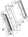
- the polarization system of the invention is incorporated in a panel mount electrical connector assembly which includes a panel 10 having an elongated opening 12 provided with an enlarged area 14 at one end of the opening.
- a mounting hole 16 is provided through the panel at each opposite end of the elongated opening. Therefore, it can be seen that the opening is generally T-shaped defining a leg portion 12a for receiving an elongated mating portion of the connector, as described hereinafter, and a cross portion defining enlarged area 14.
- the assembly includes an electrical connector, generally designated 18, which includes a one-piece housing, generally designated 20, unitarily molded of dielectric material such as plastic or the like.
- the molded plastic housing includes a mounting flange 22 for interfacing with a back side 10a of panel 10.
- An elongated mating portion 24 projects forwardly of mounting flange 22 for insertion through leg portion 12a of panel opening 12.
- the mating portion includes a plurality of "silos" 24a within which are mounted a plurality of conductive terminals (not shown).
- a mounting post 26 is integrally molded with connector housing 20 at each opposite end of mounting flange 22. The posts have forward portions 26a which are inserted into mounting holes 16 in panel 10.
- FIG. 1 which shows the invention oriented 180° from the view in Figure 1, the elongated mating portion 24, including silos 24a, of connector 18 is inserted through leg portion 12a of panel opening 12.
- a pair of fasteners 28 and washers 30 are used to fix connector 18 to panel 10.
- mounting posts 26 (Fig. 1) may be internally threaded, and fasteners 30 may have externally threaded shank portions 28 for threadingly engaging the mounting posts to secure the connector to the panel, with mating portion 24 and silos 24a projecting through panel opening 12.
- a mating connector is mateable with mating portion 24 in the direction of arrow "A" (Fig. 2). This interconnection may be in a blind mate application, and mating connector 32 includes an angled flange 34 about the periphery thereof to facilitate mating of the connectors. Mating connector 32 also mounts a plurality of conductive terminals (not shown) for electrical connection to the terminals within silos 24a of panel mounted connector 18.
- the mating connector itself, may be mounted on a second panel, a circuit board or the like by means of a pair of bifurcated mounted posts 36 (Fig. 2).
- the polarization system of the invention contemplates the provision of a pair of polarizing projections 38 located only at one end of mating portion 24 and insertable into enlarged area 14 of panel opening 12. It can be seen that one of the pair of polarizing projections 38 is located at each opposite side of mating portion 24 at the one end thereof.
- polarizing projections 38 are molded as integral gussets between mounting flange 22 and mating portion 24 of the connector housing.
- polarizing projections 38 can be seen when an operator looks at any particular side of mating portion 24 of the connector. Therefore, the operator readily will ascertain that the projections must be inserted into a particular aperture configuration in the panel, namely enlarged area 14 of panel opening 12.
- redundancy is provided in the event that localized forces on one side of the connector breaks one of the polarizing projections. Even if only one projection still remains, the mating portion of the connector can be inserted through panel opening 12 only when the remaining polarizing projection is aligned with enlarged area 14 of panel opening 12.
Landscapes
- Connector Housings Or Holding Contact Members (AREA)
Applications Claiming Priority (2)
| Application Number | Priority Date | Filing Date | Title |
|---|---|---|---|
| US20905598A | 1998-12-09 | 1998-12-09 | |
| US209055 | 1998-12-09 |
Publications (1)
| Publication Number | Publication Date |
|---|---|
| EP1009072A2 true EP1009072A2 (de) | 2000-06-14 |
Family
ID=22777138
Family Applications (1)
| Application Number | Title | Priority Date | Filing Date |
|---|---|---|---|
| EP99124293A Withdrawn EP1009072A2 (de) | 1998-12-09 | 1999-12-06 | Polarisierter schalttafelmontierter elektrischer Verbinder |
Country Status (2)
| Country | Link |
|---|---|
| EP (1) | EP1009072A2 (de) |
| KR (1) | KR20000047979A (de) |
Cited By (1)
| Publication number | Priority date | Publication date | Assignee | Title |
|---|---|---|---|---|
| JP2017004881A (ja) * | 2015-06-15 | 2017-01-05 | タイコエレクトロニクスジャパン合同会社 | 電気コネクタ |
-
1999
- 1999-12-06 EP EP99124293A patent/EP1009072A2/de not_active Withdrawn
- 1999-12-08 KR KR1019990055648A patent/KR20000047979A/ko not_active Abandoned
Cited By (1)
| Publication number | Priority date | Publication date | Assignee | Title |
|---|---|---|---|---|
| JP2017004881A (ja) * | 2015-06-15 | 2017-01-05 | タイコエレクトロニクスジャパン合同会社 | 電気コネクタ |
Also Published As
| Publication number | Publication date |
|---|---|
| KR20000047979A (ko) | 2000-07-25 |
Similar Documents
| Publication | Publication Date | Title |
|---|---|---|
| EP0441477B1 (de) | Schwimmend in einer Schalttafel montierbare elektrische Steckverbinderanordnung | |
| US5417590A (en) | Plug and socket electrical connector system | |
| US5407363A (en) | Floating panel mounting system for electrical connectors | |
| EP0702429B1 (de) | Polarisationselemente für elektrisches Verbindersystem mit Einsteckhilfe | |
| US5383799A (en) | Multi-purpose plug-in electrical outlet adaptor | |
| US11658433B2 (en) | Connector | |
| EP0706237B1 (de) | Elektrischer Verbinder mit Lagesicherungsvorrichtung für die Kontakte und Führungsvorrichtung eines komplimentären Verbinders | |
| US5888093A (en) | Floating panel mounting system for electrical connectors | |
| US5277611A (en) | Arrangement for connecting an electrical connector to a printed circuit board | |
| US6638105B1 (en) | Self-retaining board lock for electrical connector | |
| EP1119078B1 (de) | Kabelbaumverbinder | |
| US6305961B1 (en) | EMI gasket for connector assemblies | |
| US6776637B2 (en) | Panel mounted electrical connector movable relative to the panel | |
| US4585284A (en) | Transition adapter connector employing a printed circuit board | |
| EP0622868B1 (de) | Anschlussdosen-Montagesatz für Datenübertragung | |
| US6866552B2 (en) | Electrical connector with a terminal pin alignment plate | |
| US6890200B1 (en) | Floatable panel mount cable assembly | |
| US5772469A (en) | Floating panel mounting system for electrical connectors | |
| US5281155A (en) | Electrical connector with electrostatic discharge protection | |
| CN1230039A (zh) | 电连接器的电容耦合适配器 | |
| US6174185B1 (en) | Panel mounted connector | |
| EP1009072A2 (de) | Polarisierter schalttafelmontierter elektrischer Verbinder | |
| EP1033787A1 (de) | Elektrischer Verbinder mit Anschlusstiften | |
| US6074222A (en) | Cable end connector | |
| US6146172A (en) | Electrical connector |
Legal Events
| Date | Code | Title | Description |
|---|---|---|---|
| PUAI | Public reference made under article 153(3) epc to a published international application that has entered the european phase |
Free format text: ORIGINAL CODE: 0009012 |
|
| AK | Designated contracting states |
Kind code of ref document: A2 Designated state(s): AT BE CH CY DE DK ES FI FR GB GR IE IT LI LU MC NL PT SE |
|
| AX | Request for extension of the european patent |
Free format text: AL;LT;LV;MK;RO;SI |
|
| STAA | Information on the status of an ep patent application or granted ep patent |
Free format text: STATUS: THE APPLICATION HAS BEEN WITHDRAWN |
|
| 18W | Application withdrawn |
Withdrawal date: 20000615 |