EP1009114A2 - Empfänger für den Empfang von digitalen Rundfunkübertragungen - Google Patents
Empfänger für den Empfang von digitalen Rundfunkübertragungen Download PDFInfo
- Publication number
- EP1009114A2 EP1009114A2 EP99309963A EP99309963A EP1009114A2 EP 1009114 A2 EP1009114 A2 EP 1009114A2 EP 99309963 A EP99309963 A EP 99309963A EP 99309963 A EP99309963 A EP 99309963A EP 1009114 A2 EP1009114 A2 EP 1009114A2
- Authority
- EP
- European Patent Office
- Prior art keywords
- broadcast
- ensemble
- processing
- signal
- frequency
- Prior art date
- Legal status (The legal status is an assumption and is not a legal conclusion. Google has not performed a legal analysis and makes no representation as to the accuracy of the status listed.)
- Ceased
Links
- 230000005540 biological transmission Effects 0.000 title claims abstract description 36
- 238000012545 processing Methods 0.000 claims abstract description 58
- 238000000034 method Methods 0.000 claims abstract description 30
- 239000000969 carrier Substances 0.000 claims description 9
- 238000012937 correction Methods 0.000 claims description 7
- 238000006243 chemical reaction Methods 0.000 claims description 6
- 230000010365 information processing Effects 0.000 claims description 2
- 230000002123 temporal effect Effects 0.000 claims description 2
- 230000015556 catabolic process Effects 0.000 description 6
- 238000006731 degradation reaction Methods 0.000 description 6
- 230000000694 effects Effects 0.000 description 4
- 238000010586 diagram Methods 0.000 description 3
- 238000003780 insertion Methods 0.000 description 3
- 230000037431 insertion Effects 0.000 description 3
- 238000005259 measurement Methods 0.000 description 3
- 230000006641 stabilisation Effects 0.000 description 3
- 239000000203 mixture Substances 0.000 description 2
- 235000008694 Humulus lupulus Nutrition 0.000 description 1
- 230000003044 adaptive effect Effects 0.000 description 1
- 230000021615 conjugation Effects 0.000 description 1
- 125000004122 cyclic group Chemical group 0.000 description 1
- 230000000593 degrading effect Effects 0.000 description 1
- 230000001419 dependent effect Effects 0.000 description 1
- 238000013461 design Methods 0.000 description 1
- 238000005562 fading Methods 0.000 description 1
- 239000000463 material Substances 0.000 description 1
- 239000013307 optical fiber Substances 0.000 description 1
- 230000010363 phase shift Effects 0.000 description 1
- 230000002035 prolonged effect Effects 0.000 description 1
- 238000000926 separation method Methods 0.000 description 1
- 230000005236 sound signal Effects 0.000 description 1
- 238000001228 spectrum Methods 0.000 description 1
- 230000003068 static effect Effects 0.000 description 1
- 230000001360 synchronised effect Effects 0.000 description 1
- 238000012546 transfer Methods 0.000 description 1
- 230000000007 visual effect Effects 0.000 description 1
- 238000012800 visualization Methods 0.000 description 1
Images


Classifications
-
- H—ELECTRICITY
- H04—ELECTRIC COMMUNICATION TECHNIQUE
- H04H—BROADCAST COMMUNICATION
- H04H20/00—Arrangements for broadcast or for distribution combined with broadcast
- H04H20/20—Arrangements for broadcast or distribution of identical information via plural systems
- H04H20/22—Arrangements for broadcast of identical information via plural broadcast systems
-
- H—ELECTRICITY
- H04—ELECTRIC COMMUNICATION TECHNIQUE
- H04H—BROADCAST COMMUNICATION
- H04H2201/00—Aspects of broadcast communication
- H04H2201/10—Aspects of broadcast communication characterised by the type of broadcast system
- H04H2201/20—Aspects of broadcast communication characterised by the type of broadcast system digital audio broadcasting [DAB]
Definitions
- This invention relates to broadcast receivers and in particular, but not exclusively, to digital audio broadcast (DAB) receivers and to methods of signal processing implemented in said receivers.
- DAB digital audio broadcast
- the invention is not so limited and extends to broadcast transmissions over other media such as optical fibre.
- the broadcast DAB signal may typically comprise a mixture of stereo and mono broadcasts and data services carried in a single ensemble.
- a ensemble may comprise a variable number of services, depending on the quality (i.e. bit rate) required and this may change during the day dependent on broadcast schedules.
- a typical DAB system is that developed under the Eureka 147 Project with a DAB transmitted signal now specified by ETSI specification ETS 300401, the entire contents of which are incorporated herein by reference.
- Alternative schemes exist in U.S.A., e.g. In-Band, On-Channel (IBOC), Digital Audio Radio (DAR), and elsewhere.
- the Eureka 147 DAB system is a reliable multi-service digital radio broadcasting system designed specifically for robust reception by mobile portable and fixed receivers using non-directional antennas.
- the ETS 300 401 signal contains time interleaving and error-correcting codes that are designed to cope with signal loss over a short duration.
- the Eureka 147 system comprises three main components; namely audio coding; transmission coding and multiplexing, and OFDM modulation.
- the audio coding component uses a coding scheme known as MPEG-1 Audio Layer II encoding.
- Other services to be transmitted may be encoded using suitable coding algorithms.
- the multiplex data is assembled into transmission frames which are made up of a synchronisation channel, a fast information channel (FIC) and a main service channel (MSC).
- FIC fast information channel
- MSC main service channel
- the synchronisation channel contains a null symbol and a sync symbol (otherwise known as the phase reference signal) which convey reference frequency and timing information to allow receivers to synchronise to and to decode the received DAB signal.
- the FIC contains information relating to the composition of the multiplex and informs the receivers how to extract and decode the information for individual services.
- the MSC contains the audio frames or data packets corresponding to different services in the multiplex, and these frames are usually time interleaved and referred to herein as common interleaved frames (CIF).
- CIF common interleaved frames
- the multiplex data is subjected to convolutional forward error correction channel coding, time interleaving and frequency interleaving to provide strong protection against bit errors.
- the OFDM scheme consists of a large number of orthogonally spaced subcarriers transmitted at a relatively slow symbol rate, and the broadcast signal comprising the group of subcarriers is known as an ensemble.
- the broadcast signal comprising the group of subcarriers is known as an ensemble.
- Eureka 147 DAB Mode I there are 1536 carriers spaced at 1KHz separation. Each carrier is independently modulated using differential quadrature phase shift keying (D-QPSK) and the multiplex data is distributed amongst all the carriers, occupying approximately 1.54MHz of spectrum.
- D-QPSK differential quadrature phase shift keying
- the low symbol rate together with the guard period which is added to each symbol provides significant protection against multipath interference.
- an ensemble is acquired and processed so that all of the services making up the multiplex in the main service channel of the ensemble are available for selection by the user.
- the BBC multiplex may typically contain national services Radio 1, Radio 2, Radio 3, Radio 4, Radio 5 Live and further audio or data services. Information identifying the audio and data services currently provided on the multiplex and how to extract a selected service is contained in the FIC. Having acquired the ensemble containing the BBC multiplex, the user may readily select which audio or data service he required from that multiplex without requiring retuning of the receiver.
- a multi-channel reception facility would require a separate radio frequency (RF) front-end to allow a further ensemble to be acquired without disrupting reception and reproduction of the current service, and this would increase the cost of the receiver.
- RF radio frequency
- a DAB receiver is described herein with a single RF front-end which, whilst tuned to a primary signal, can acquire and monitor other signals without appreciable disruption to the primary signal, thereby extending the capabilities of the receiver at little cost.
- the powerful time interleaving and error correction capabilities of the Digital Audio Broadcast (DAB) signal are exploited to allow a receiver which is tuned to and decoding a particular ensemble to tune (hop), for a relatively short time, to a second frequency before returning to the primary frequency.
- DAB Digital Audio Broadcast
- a second ensemble can be acquired, synchronised to and partially demodulated.
- the powerful time interleaving and error correction capabilities of such a broadcast signal mean that any degradation to the audio quality of the primary ensemble due to the loss of samples during the hop, is minimal.
- this invention provides a digital audio broadcast receiver for receiving at least two broadcast ensembles, each ensemble being made up of a plurality of transmission frames and each transmission frame including an information channel and a time interleaved main service channel, said broadcast receiver including means for acquiring and processing during a plurality of relatively long periods a given broadcast ensemble to extract and reproduce selected audio or other service data from said main service channel, said means for acquiring and processing also being operable to process a further broadcast ensemble at least to detect the presence thereof during one or more relatively short intervals interspersed with said relatively long periods, thereby to obtain data relating to said further ensemble.
- intervals are sufficiently short that there is little or no appreciable degradation of the audio or other service data from said given broadcast ensemble.
- the effect of the data lost from the given ensemble during said short intervals is diluted and spread over time, due to said interleaving.
- said acquiring and processing means includes means for providing in-fill data for being processed to replace data from a portion of said transmission frame from said first ensemble lost during said one or more relatively short intervals.
- the in-fill data may comprise a stream of binary zeroes or ones, or a stream of random or pseudo-random bits.
- the acquiring and processing means may conveniently comprise:
- said demodulation means, said frequency de-interleaving means and said information channel processing means are preferably operable during said relatively short intervals to process information from said further broadcast ensemble.
- said acquiring and processing means preferably comprise:
- said means for acquiring and processing is operable during said one or more intervals to capture a sample sequence from said further broadcast ensemble, and to process said sample sequence to obtain an estimate of the approximate symbol timing.
- said means for acquiring and processing is preferably operable during said one or more intervals to capture a sample sequence from said further broadcast ensemble and to process said sample sequence to determine the transmission mode of said further broadcast ensemble.
- each of said ensembles is transmitted as a multi-carrier or OFDM signal comprising an ensemble of sub-carriers at a known relative spacing, and each of the said transmission frames of the ensembles includes a sync symbol
- said means for acquiring and processing is preferably operable during said intervals to capture from one or more transmission frames of said further broadcast ensemble a complete frame of samples succession of samples making up a partial or complete frame, and preferably further includes sync symbol processing means operable to process each of said captured samples to determine whether it is the sync symbol.
- the sync symbol processing means is preferably further operable to process the sync symbol sample to determine the coarse frequency offset of the ensemble.
- said sync symbol processing means preferably includes means for processing said sync symbol to obtain a signal having a generally regular data structure, and means for applying a comb filter function generally matched to said structure thereby to deduce the coarse frequency offset of said multi-carrier signal.
- this invention provides a method of receiving and processing two or more broadcast ensembles each comprising a plurality of transmission frames, with each transmission frame including an information channel, and a main service channel which is time interleaved, said method comprising acquiring and processing during relatively long periods a given said broadcast ensemble to extract and reproduce audio or other service data, and processing another broadcast ensemble during relatively short periods interspersed with said longer periods, at least to detect the presence thereof.
- the processing of the other broadcast ensemble may determine just the presence of another ensemble, and/or the frequency and timing thereof, and/or it may extract information from the information channel.
- this invention provides a broadcast receiver for acquiring and processing a plurality of different broadcast signals, each said broadcast signal comprising data in time interleaved and/or encoded form, said receiver comprising means for acquiring and processing during a plurality of relatively long periods a given broadcast signal to extract and reproduce audio or other service data, wherein said means for acquiring and processing is also operable to at least detect the presence of a further broadcast signal during one or more relatively short intervals interspersed with said relatively long periods, whereby data from said further broadcast is obtained whilst the audio or other service data from said given broadcast channel is reproduced.
- the embodiment described below is a DAB receiver demodulating a signal conforming to the ETS 300 401 specification.
- the ETS 300 401 signal contains time-interleaving and error correcting codes that are designed to cope with the loss of signal for a short duration.
- the signal is based on multicarrier modulation (OFDM) which consists of a large number of orthogonally spaced subcarriers transmitted at a relatively slow symbol rate.
- OFDM multicarrier modulation
- the DAB specification has four modes whereby the number of subcarriers, the symbol rate and hence the number of symbols making up a frame varies.
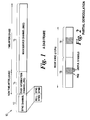
- Figure 1 shows a typical transmission frame 10.
- the signal is frame based consisting of two symbols used for synchronisation purposes (called the Synchronisation Channel) 12, a few symbols containing the fast information channel 14 (FIC) and the remainder making up the main service channel (MSC) 16.
- Each symbol in mode 1 codes for 3072 bits (1536 carriers, with two bits per carrier).
- the transmission frame for mode 1 consists of 2 Sync channel symbols, 3 FIC symbols and 72 MSC symbols giving a frame duration of 96ms.
- the FIC channel is not time-interleaved, which allows fast decoding.
- the FIC contains details of the contents of the audio subchannels contained in the MSC.
- the MSC is divided into a number of common interleaved frames (CIFs).
- CIF contains all the information to decode 24ms of audio data and they occur at an average rate of one per 24ms for all DAB modes.
- Time interleaving operates by spreading data within one CIF over 16 CIFs, hence over a duration of 384ms. Note that the receiver is not required to capture and demodulate every symbol because only part of each CIF is occupied by a particular subchannel.
- Figure 2 shows the useful symbols pertaining to a particular subchannel beginning half-way through a mode 4 CIF 18. Because of the differential nature of DAB modulation, the symbol prior to a symbol containing wanted information is required and so only these, together with the immediately preceding symbol (referred to as a phase reference signal or PRS), need be captured.
- PRS phase reference signal
- FIG 3 is a schematic diagram illustrating the basic structure and operation of a DAB receiver 19 producing audio and displaying information in accordance with this invention.
- the receiver 18 is shown as having an upper path 20 and a lower path 22.
- these paths represent the operation of the receiver at different times, and the upper and lower paths are not separate physical channels.
- the upper path represents processing of a main broadcast ensemble and the lower path represents a processing facility for use during channel hopping to process a second ensemble without appreciably disrupting reproduction of the selected subchannel main broadcast ensemble.
- the upper path shows a demodulation chain consisting of the necessary inverse operations to decode the signal transmitted according to the ETS 300 401 specification.
- the path consists of an RF downconversion stage 24 which amplifies and filters the wanted RF signal, a frequency shifting stage 26 which uses a tuning signal from a control 28 to modulate the signal down from the carrier frequency FO to an intermediate frequency (IF) suitable for analog to digital conversion (ADC) at an analog to digital converter 30.
- IF intermediate frequency
- ADC analog to digital conversion
- a sample capture system strips the guard period off the transmitted symbols and converts them to the frequency domain with a Fast Fourier Transform (FFT) at 32.
- FFT Fast Fourier Transform
- FIC symbols (not requiring time deinterleaving) are passed to a Viterbi decoder 38 (for channel error correction) and a FIC decoder 40 which passes suitable information to a display device 42.
- Other MSC symbols in general containing audio, pass via a time deinterleaver 44, a Viterbi decoder 46 and an MPEG audio decoder 48, to produce an audio signal for reproduction at 50.
- the Sync channel symbols are used to update the receiver's tracking parameters, namely frequency tracking and symbol tracking.
- the lower path 22 consists of the same symbol processing elements as the FIC processing of the upper path 20. In this case, during the time periods when the primary ensemble alone is being processed, no signal is passed to the FFT unit and the lower path 22 processing is essentially disabled.
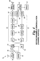
- Figure 4 illustrates the same receiver 18 tuned to a new frequency F1 in a frequency hop, to extract data from a second ensemble broadcast at frequency F1.
- the switch-over to frequency F1 is timed to coincide with the arrival of the Sync channel and FIC symbols of the second ensemble.
- the Sync channel symbols allow the receiver 18 to update its tracking parameters whilst the FIC symbols are passed to the lower path 22 for FIC decoding.
- the lower path is supplied with the downconverted digital baseband signal from the analog to digital converter 30.
- Zeroed samples are passed from a source 52 to the upper path 20 for the duration of the time tuned to frequency F1.
- the time deinterleaving spreads the zeros over a large number of bits, resulting in errors spread more evenly over time.
- the Viterbi decoder is presented with a higher than usual error rate which, depending on the conditions, may be fully or partially corrected.
- the frame-based transmission and processing allows short time slots or channel hop intervals to be allocated for background processing the second ensemble (i.e. the lower path 22) interspersed with the much longer periods during which the main ensemble is processed (i.e. the upper path 20), without disrupting the reconstruction of the selected subchannels of the main ensemble being reproduced.
- the time deinterleaving spreads the effects of zero insertion over 16 CIFs, and hence zeros inserted in CIF(n) are spread over data passed to the Viterbi decoder 38 for CIF(n)...CIF(n+15). It is necessary to maximally spread the times that data is zeroed to avoid concentrating errors. Hence what we refer to as a channel hopping ratio of 1/12 would be performed by zeroing data once every twelve CIFs.
- D 1 the time spent absent from the main ensemble is denoted by D 1 and the time spent capturing data from the secondary ensemble is denoted D 2 (D 2 ⁇ D 1 ). Practical values for D 1 and D 2 are discussed below.
- D 2 is the interval during which data from the RF front end is supplied to the lower path 22 for processing.
- the extent by which the increase in errors degrades the signal depends on many factors.
- the main dependencies are the level of error protection encoded into the signal, the operating environment and the percentage of time spent in the second channel.
- the ETS 300 401 specification defines a range of protection levels which range from level 1 (strong) to level 5 (weak). The stronger levels are used for mobile receiver environments where the effect of Rayleigh fading causes large amplitude and phase changes over time.
- a receiver 19 will judge the suitability of switching to a channel hopping mode depending on the protection level of the main signal and the operating environment.
- a stationary receiver 19 demodulating a level 1 signal spending 1/16th of its time in the second channel will suffer virtually no degradation in performance.
- a rapidly moving mobile receiver 19 demodulating a signal with a weak protection level could be affected to the point where noticeable audio distortion occurs.
- BER bit error rate
- the method by which a second ensemble is acquired whilst continuing to decode a main ensemble falls into two distinct parts. Firstly coarse symbol timing determines both the transmission mode of the second ensemble and the approximate location of the start of a symbol. Thereafter the second ensemble is located accurately in frequency and time.
- Coarse symbol timing is obtained by tuning to the trial frequency F1, corresponding to the suspected frequency of the second ensemble, capturing a random segment of contiguous samples, and returning to the main ensemble. Longer capture times will, in general, improve performance. These samples are background processed to determine both the transmission mode of the ensemble (if present) and an approximate location of the timing of each symbol. The mode and symbol timing may be determined quite robustly using a correlation technique that exploits the cyclic repetition (i.e. of the symbol in the time domain i.e. the guard period).
- a correlation vector r is constructed using: for and
- the correlation is repeated for all four possible modes and the maximum correlation peak, together with the timing offset is recorded for each. Note that mismatching the trial mode and the actual mode gives a substantially noise-like correlation result. If sufficient difference exists between the highest and second highest correlation peak the mode and timing offset is deemed to be found otherwise the acquisition is aborted.
- a whole frame's worth of logically consecutive samples are captured and scanned for the presence of a Sync symbol. Because of the repeating frame structure of the signal, a complete frame of samples can be captured over time which are not contiguous. For instance if a mode 1 signal has been detected, a mode 1 frame (96ms in duration) could be captured in four lots of 24ms, each capture separated by 384ms. In fact, the scanning proceeds on the first capture and if a Sync symbol is not found, the next capture occurs and so on until four captures have occurred. If the Sync symbol has failed to be identified, the acquisition process is terminated.
- a second ensemble may be continuously tracked (and hence demodulated) in time and frequency using the channel hopping method by exploiting the fact that, in practice, while the channel transfer function may change rapidly a receiver 19 is not required to respond rapidly. This is largely due to the inherent robustness of OFDM with DQPSK subcarriers and its lack of a requirement to perform adaptive equalisation. Hence updating the second ensemble frequency offset and symbol timing every, say, 384ms will in most circumstances be adequate. Note that the required capture times for the second ensemble Sync Channel/FIC are much less than 24ms. For instance, in mode 1 only 5 symbols are required from a DAB frame containing 77 symbols.
- Tracking to the main ensemble will operate normally except in the case where the Sync Channel and/or FIC of the second ensemble overlap in time with those of the main ensemble.
- the same slow tracking arguments apply to the main ensemble which, in any case, will be serviced the majority of the time.
- the receiver demodulates the FIC only of the second ensemble. This is updated infrequently according to ETSI 300 401 (the multiplex can change at most only once every six seconds and in most cases much less frequently) and is protected with a relatively strong convolutional code which helps with imperfect tracking.
- maximising the capture times can be useful during acquisition for several reasons.
- the correlation technique used in the coarse timing and mode determination phase benefits from longer captured sequences.
- the speed of Sync symbol scanning benefits from longer capture.
- the capture time can still be greater than a CIF duration if the number of wanted symbols is less than the maximum number of symbols in a CIF,N c .
- the maximum main ensemble absence time D 1 is obtained by discarding symbols straight after the last one captured up until the phase reference symbol of the next wanted CIF.
- the maximum value of the time spent absent from the main ensemble D 1 is the duration of N c -1 symbols.
- AGC automatic gain control
- the AGC implemented in a DAB receiver typically consists of at least two autonomous parts - an analog control residing in the early stages of the RF unit and a digitally controlled gain signal that operates prior to and following the ADC.
- both controls are typically quite slow acting (ie. time constants much greater than useful values of D y ).
- a rapid AGC adaption needs to occur.
- the receiver utilises a hardware signal to instruct the early RF stage AGC to reset and quickly readapt within a time ⁇ D y is required.
- software within the receiver is provided to restore the state (gain level) of the digitally controlled AGC to that previously used during the last hop. If the level is not previously known or sufficiently inaccurate, a rapid convergence mode is used.
- the channel hopping ratio of 1/16 th and the nominal capture time of 24ms are given merely as examples. Many variations are possible and have to be weighed against BER degradation and implementation complexity.
Landscapes
- Engineering & Computer Science (AREA)
- Signal Processing (AREA)
- Circuits Of Receivers In General (AREA)
Applications Claiming Priority (2)
| Application Number | Priority Date | Filing Date | Title |
|---|---|---|---|
| GBGB9827108.3A GB9827108D0 (en) | 1998-12-10 | 1998-12-10 | Broadcast receivers |
| GB9827108 | 1998-12-10 |
Publications (2)
| Publication Number | Publication Date |
|---|---|
| EP1009114A2 true EP1009114A2 (de) | 2000-06-14 |
| EP1009114A3 EP1009114A3 (de) | 2000-07-19 |
Family
ID=10843930
Family Applications (1)
| Application Number | Title | Priority Date | Filing Date |
|---|---|---|---|
| EP99309963A Ceased EP1009114A3 (de) | 1998-12-10 | 1999-12-10 | Empfänger für den Empfang von digitalen Rundfunkübertragungen |
Country Status (2)
| Country | Link |
|---|---|
| EP (1) | EP1009114A3 (de) |
| GB (1) | GB9827108D0 (de) |
Cited By (4)
| Publication number | Priority date | Publication date | Assignee | Title |
|---|---|---|---|---|
| WO2008002000A1 (en) * | 2006-06-30 | 2008-01-03 | Electronics And Telecommunications Research Institute | Method for transforming terrestrial dmb contents and gateway employing the same |
| EP1630988A3 (de) * | 2004-08-27 | 2010-12-01 | Robert Bosch GmbH | Zeitlich gemultiplexter Empfang auf zwei Trägerfrequenzen im digitalen Rundfunk |
| WO2011114115A1 (en) * | 2010-03-18 | 2011-09-22 | Imagination Technologies Limited | Rf receiver for time slice services |
| EP2051392A4 (de) * | 2006-09-01 | 2012-09-05 | Clarion Co Ltd | Rundfunkempfänger und rundfunksuchverfahren |
Citations (2)
| Publication number | Priority date | Publication date | Assignee | Title |
|---|---|---|---|---|
| EP0689071A1 (de) | 1993-05-03 | 1995-12-27 | Litton Systems, Inc. | Faseroptische Kopplung |
| GB2320868A (en) | 1996-12-03 | 1998-07-01 | Ensigma Ltd | Measuring coarse frequency offset of a multi-carrier signal |
Family Cites Families (4)
| Publication number | Priority date | Publication date | Assignee | Title |
|---|---|---|---|---|
| FI96555C (fi) * | 1994-06-16 | 1996-07-10 | Nokia Technology Gmbh | Digitaalinen yleislähetysjärjestelmä ja järjestelmässä käytettäväksi tarkoitettu vastaanotin |
| FI942971A0 (fi) * | 1994-06-20 | 1994-06-20 | Nokia Technology Gmbh | Foerfarande foer vaexling av signalkaelle i mottagaren i ett digitalt universalsaendningssystem, samt mottagare foer digitalt universalsaendningssystem |
| EP0790722B1 (de) * | 1996-02-16 | 2003-12-03 | STMicroelectronics S.r.l. | Automatische Detektion des Übertragungsmodus in Empfängern von digitalen Tonsignalen |
| DE19614322A1 (de) * | 1996-04-11 | 1997-10-16 | Grundig Ag | Verfahren für den Empfang und die Auswertung von RDS-Datenströmen mehrerer Sender |
-
1998
- 1998-12-10 GB GBGB9827108.3A patent/GB9827108D0/en not_active Ceased
-
1999
- 1999-12-10 EP EP99309963A patent/EP1009114A3/de not_active Ceased
Patent Citations (2)
| Publication number | Priority date | Publication date | Assignee | Title |
|---|---|---|---|---|
| EP0689071A1 (de) | 1993-05-03 | 1995-12-27 | Litton Systems, Inc. | Faseroptische Kopplung |
| GB2320868A (en) | 1996-12-03 | 1998-07-01 | Ensigma Ltd | Measuring coarse frequency offset of a multi-carrier signal |
Cited By (5)
| Publication number | Priority date | Publication date | Assignee | Title |
|---|---|---|---|---|
| EP1630988A3 (de) * | 2004-08-27 | 2010-12-01 | Robert Bosch GmbH | Zeitlich gemultiplexter Empfang auf zwei Trägerfrequenzen im digitalen Rundfunk |
| WO2008002000A1 (en) * | 2006-06-30 | 2008-01-03 | Electronics And Telecommunications Research Institute | Method for transforming terrestrial dmb contents and gateway employing the same |
| CN101513054B (zh) * | 2006-06-30 | 2011-04-20 | 韩国电子通信研究院 | 用于变换地面数字多媒体广播内容的方法和采用该方法的网关 |
| EP2051392A4 (de) * | 2006-09-01 | 2012-09-05 | Clarion Co Ltd | Rundfunkempfänger und rundfunksuchverfahren |
| WO2011114115A1 (en) * | 2010-03-18 | 2011-09-22 | Imagination Technologies Limited | Rf receiver for time slice services |
Also Published As
| Publication number | Publication date |
|---|---|
| EP1009114A3 (de) | 2000-07-19 |
| GB9827108D0 (en) | 1999-02-03 |
Similar Documents
| Publication | Publication Date | Title |
|---|---|---|
| EP0938203A1 (de) | Empfänger und empfängerschaltung | |
| US7555065B1 (en) | Adaptive signal tuning for digital radio receivers operating in FM bands | |
| US6731702B1 (en) | Null symbol position detecting method, null symbol position detecting apparatus, and receiver | |
| US6591092B1 (en) | Signal receiving apparatus with a gain controller and method thereof | |
| KR100429696B1 (ko) | 간섭을받는무선채널을통해디지털데이터를송신하는방법및그것을통해송신된디지털데이터를수신하는장치 | |
| JPWO2000054445A1 (ja) | ディジタル放送受信装置 | |
| KR101514099B1 (ko) | 신호 발견을 위한 방법 및 장치 | |
| EP0788264A2 (de) | Sender und Empfänger für OFDM | |
| JP2002094402A (ja) | デジタル放送受信装置及びデジタル放送受信方法 | |
| EP1009114A2 (de) | Empfänger für den Empfang von digitalen Rundfunkübertragungen | |
| KR19980042347A (ko) | 디지털 음성방송의 판별장치 | |
| EP2104237A2 (de) | Empfangsvorrichtung und Verfahren zum Herstellen einer Kanalliste in der Empfangsvorrichtung | |
| KR102872274B1 (ko) | 단일 무선 주파수 튜너를 포함하는 라디오 장치에서 주파수 풀 스캔 시간을 단축시키는 방법 및 장치 | |
| JP3514624B2 (ja) | ディジタル放送受信機 | |
| CA2265330C (en) | Receiver for digital broadcast signal including transmitter identification information | |
| CA2265260C (en) | Digital broadcast receiver | |
| KR20050063154A (ko) | Dmb 수신기에서 정수 주파수 오차 정정 장치 및 방법 | |
| KR19990058954A (ko) | 디지털 방송수신 방법 | |
| KR100602255B1 (ko) | 디브이비-티와 디에이비 겸용 직교분할대역 수신시스템 | |
| KR20050063155A (ko) | Dmb 수신기에서의 전송 모드 검출 장치 및 방법 | |
| JPH1155168A (ja) | 受信機のアンテナ・ダイバーシティ方法 | |
| JP3374009B2 (ja) | ラジオ受信機 | |
| JP3363764B2 (ja) | Ofdm放送受信機 | |
| KR100820826B1 (ko) | 방송 수신기 및 처리 방법 | |
| EP1150469A2 (de) | Neuabstimmung in einem DAB-Empfänger |
Legal Events
| Date | Code | Title | Description |
|---|---|---|---|
| PUAI | Public reference made under article 153(3) epc to a published international application that has entered the european phase |
Free format text: ORIGINAL CODE: 0009012 |
|
| PUAL | Search report despatched |
Free format text: ORIGINAL CODE: 0009013 |
|
| AK | Designated contracting states |
Kind code of ref document: A2 Designated state(s): AT BE CH CY DE DK ES FI FR GB GR IE IT LI LU MC NL PT SE |
|
| AX | Request for extension of the european patent |
Free format text: AL;LT;LV;MK;RO;SI |
|
| AK | Designated contracting states |
Kind code of ref document: A3 Designated state(s): AT BE CH CY DE DK ES FI FR GB GR IE IT LI LU MC NL PT SE |
|
| AX | Request for extension of the european patent |
Free format text: AL;LT;LV;MK;RO;SI |
|
| 17P | Request for examination filed |
Effective date: 20001221 |
|
| AKX | Designation fees paid |
Free format text: AT BE CH CY DE DK ES FI FR GB GR IE IT LI LU MC NL PT SE |
|
| 17Q | First examination report despatched |
Effective date: 20061211 |
|
| RAP1 | Party data changed (applicant data changed or rights of an application transferred) |
Owner name: ENSIGMA TECHNOLOGIES LIMITED |
|
| APBK | Appeal reference recorded |
Free format text: ORIGINAL CODE: EPIDOSNREFNE |
|
| APBN | Date of receipt of notice of appeal recorded |
Free format text: ORIGINAL CODE: EPIDOSNNOA2E |
|
| APBR | Date of receipt of statement of grounds of appeal recorded |
Free format text: ORIGINAL CODE: EPIDOSNNOA3E |
|
| APAF | Appeal reference modified |
Free format text: ORIGINAL CODE: EPIDOSCREFNE |
|
| APBT | Appeal procedure closed |
Free format text: ORIGINAL CODE: EPIDOSNNOA9E |
|
| STAA | Information on the status of an ep patent application or granted ep patent |
Free format text: STATUS: THE APPLICATION HAS BEEN REFUSED |
|
| 18R | Application refused |
Effective date: 20151222 |