EP1009124B1 - Verfahren zur drahtlosen Übertragung über ein Antennennetz unter Verwendung unitärer Raum-Zeit-Signale - Google Patents
Verfahren zur drahtlosen Übertragung über ein Antennennetz unter Verwendung unitärer Raum-Zeit-Signale Download PDFInfo
- Publication number
- EP1009124B1 EP1009124B1 EP99309613A EP99309613A EP1009124B1 EP 1009124 B1 EP1009124 B1 EP 1009124B1 EP 99309613 A EP99309613 A EP 99309613A EP 99309613 A EP99309613 A EP 99309613A EP 1009124 B1 EP1009124 B1 EP 1009124B1
- Authority
- EP
- European Patent Office
- Prior art keywords
- matrix
- vector
- ustm
- matrices
- signal
- Prior art date
- Legal status (The legal status is an assumption and is not a legal conclusion. Google has not performed a legal analysis and makes no representation as to the accuracy of the status listed.)
- Expired - Lifetime
Links
- 238000000034 method Methods 0.000 title claims description 91
- 230000005540 biological transmission Effects 0.000 title claims description 35
- 238000003491 array Methods 0.000 title description 4
- 239000011159 matrix material Substances 0.000 claims description 186
- 239000013598 vector Substances 0.000 claims description 66
- 238000004891 communication Methods 0.000 claims description 18
- 230000004044 response Effects 0.000 claims description 6
- 108010076504 Protein Sorting Signals Proteins 0.000 claims 4
- 238000005562 fading Methods 0.000 description 17
- 238000007476 Maximum Likelihood Methods 0.000 description 9
- 230000000694 effects Effects 0.000 description 7
- 238000004458 analytical method Methods 0.000 description 5
- 230000008569 process Effects 0.000 description 5
- 230000000875 corresponding effect Effects 0.000 description 4
- 238000012549 training Methods 0.000 description 4
- 239000000654 additive Substances 0.000 description 3
- 230000000996 additive effect Effects 0.000 description 3
- 230000009466 transformation Effects 0.000 description 3
- 238000000844 transformation Methods 0.000 description 3
- 238000013459 approach Methods 0.000 description 2
- 230000008901 benefit Effects 0.000 description 2
- 239000002131 composite material Substances 0.000 description 2
- 230000003247 decreasing effect Effects 0.000 description 2
- 238000013461 design Methods 0.000 description 2
- 238000012986 modification Methods 0.000 description 2
- 230000004048 modification Effects 0.000 description 2
- 238000004088 simulation Methods 0.000 description 2
- 230000006978 adaptation Effects 0.000 description 1
- 230000002457 bidirectional effect Effects 0.000 description 1
- 238000004364 calculation method Methods 0.000 description 1
- 150000001875 compounds Chemical class 0.000 description 1
- 230000002153 concerted effect Effects 0.000 description 1
- 230000002596 correlated effect Effects 0.000 description 1
- 230000001066 destructive effect Effects 0.000 description 1
- 238000010586 diagram Methods 0.000 description 1
- 230000006870 function Effects 0.000 description 1
- 238000005457 optimization Methods 0.000 description 1
- 230000008054 signal transmission Effects 0.000 description 1
Images
Classifications
-
- H—ELECTRICITY
- H04—ELECTRIC COMMUNICATION TECHNIQUE
- H04L—TRANSMISSION OF DIGITAL INFORMATION, e.g. TELEGRAPHIC COMMUNICATION
- H04L1/00—Arrangements for detecting or preventing errors in the information received
- H04L1/02—Arrangements for detecting or preventing errors in the information received by diversity reception
- H04L1/06—Arrangements for detecting or preventing errors in the information received by diversity reception using space diversity
- H04L1/0618—Space-time coding
Definitions
- This invention relates to methods of wireless communication.
- Fading is one of several physical phenomena that tend to increase error rates, or to reduce channel capacity, in wireless transmission systems. Fading is the result of destructive interference, at the receiver, between correlated signal portions that because of scattering have arrived over different-length paths.
- differential phase modulation In which phase differences carry transmitted information.
- differential phase modulation is a known technique for single-antenna transmission and reception in fading environments, there are no known adaptations of this technique for use with multiple-antenna arrays.
- training intervals cut into the available time during which data may be transmitted.
- the length of this interval increases as the number of transmitter antennas is increased.
- the propagation coefficients can be treated as constant only over an average period of time referred to as the fading coherence interval.
- training should be repeated at least once per such interval.
- fading is very rapid in some environments, such as those in which a mobile station is operating within a rapidly moving vehicle.
- the time between fades may be too short for the communication system to learn the propagation coefficients belonging to even one transmitting antenna, much less those of a multiple antenna array.
- each message to be transmitted is transformed into a sequence of signals selected from a constellation of L possible signals, L a positive integer.
- each transmitted signal embodies a number of bits given by log L.
- log will denote the binary logarithm.
- Each of these symbols is, itself, a time sequence of complex amplitudes for transmission by the transmitting antenna or antennas.
- the transmissions by all of the antennas in the transmitting array are concerted. All of these transmissions (for a given signal) are made in the same sequence of T successive time units (which we refer to as symbol intervals), T a positive integer.
- a signal may be represented by a complex-valued matrix having T rows and M columns.
- Each column corresponds to a respective antenna of the transmitting array, and represents the sequence of complex amplitudes to be transmitted by that antenna.
- Each row corresponds to a particular one of the T symbol intervals, and describes the complex amplitude to be transmitted by each respective antenna during that interval.
- Such a set of complex amplitudes is referred to as a "symbol.”
- Each symbol is distributed in space (i.e., across the transmitting array), and each signal is composed of T symbols distributed in time.
- each signal matrix must have the property that all of its columns are orthonormal.
- P is the average power fed into each antenna.
- L signals there are L signals, and M columns per signal. Thus, over the entire constellation, there are L ⁇ M columns. Because there will typically be many signals in the constellation (constellation sizes in the hundreds of thousands, or even more, are desirable in at least some applications), L ⁇ M will typically be much greater than T. Well known mathematical properties dictate that there can be no more than T mutually orthonormal column vectors. Therefore, it will be unlikely that, given a randomly chosen pair of signal matrices, the columns of one such matrix will be orthogonal to the columns of the other.
- EP-A- 0981209 describes techniques for minimizing these correlations that are most useful when the number M of transmitting antennas is relatively small. What has been lacking, until now, is a more powerful technique that can readily generate signal constellations of low correlation when M, L, and T are relatively large, without demanding impractical amounts of computational resources.
- USTM Unitary Space-Time Modulation
- HOCHWALD B M ET AL 'Space-time modulation scheme for unknown Rayleigh fading environments' PROCEEDINGS OF THE 36 TH ANNUAL ALLERTON CONFERENCE ON COMMUNICATION, CONTROL AND COMPUTING, MONTICELLO, IL, USA, 23-25 September 1998, pages 431-440, XP000914264 1998, Urbana, IL, USA, Univ. Illinois, USA is an introductory description of USTM, including a discussion of reception and demodulation techniques and a theoretical analysis of error rates in communication by USTM.
- the product is a new T ⁇ M matrix, which also has the column-orthonormality properties that qualify it to serve as a signal matrix.
- the new T ⁇ M matrix can again be left-multiplied by ⁇ , and so on ad infinitem , to generate many T ⁇ M matrices having orthonormal columns.
- the matrix ⁇ can be tailored in such a way that the resulting product matrices tend to have relatively low correlations with each other.
- an appropriate subset of these product matrices is advantageously employed as a signal constellation.
- T ⁇ T unitary matrices that we have found useful in this regard is the class of matrices that are th roots of the T ⁇ T identity matrix. It will be appreciated that if ⁇ belongs to such a class, no more than distinct signal matrices can be generated from an initial signal matrix by repeated applications of ⁇ .
- the parameter may be chosen to equal the size L of the desired signal constellation, or it may be chosen to be larger than L. If is larger than L, the constellation is assembled by selecting a subset of size L from the generated matrices.
- the indices l and l ' are used to denote particular signal matrices. Thus, each of these indices takes on integer values from 1 to L.
- the initial signal matrix is indexed by 1
- the result of one multiplication by ⁇ is indexed by 2, and so on.
- the signal matrix ⁇ l is the result of l -1 multiplications by ⁇ .
- a method for creating a constellation of signals for wireless transmission comprises providing an initial signal in the form of a complex-valued matrix, all columns of which are orthonormal.
- the method further comprises generating a further plurality of matrices by a process that assures that each of the generated matrices is related to the initial matrix as a product of one or more multiplications of the initial matrix by a unitary matrix.
- At least one baseband signal is generated, and then it is transmitted, on a radio-frequency carrier, from an array of one or more transmission antennas.
- Each transmission of a baseband signal is carried out by transmitting a sequence of amplitudes from each of the one or more antennas of the array.
- Each such transmission is made in accordance with a signal matrix having columns and rows, in which each column represents a distinct antenna of the array, and each row represents a distinct time interval, such that the entries in each column are proportional to the amplitudes to be transmitted, in sequence, from a corresponding antenna of the array.
- the columns of each signal matrix are orthonormal.
- Each signal matrix is selected from a constellation of available signal matrices.
- Each matrix in the constellation is either an initial matrix, or it is related to the initial matrix as a product of one or more multiplications of the initial matrix by a unitary matrix.
- the matrices of the signal constellation are related to the initial matrix as products of multiplications of the initial matrix by one or more unitary matrices.
- the signal constellation is a subset of a set of matrices having a circulant correlation structure.
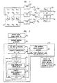
- FIG. 1 shows a baseband signal 10 input to a transmitting array of antennas 15.1-15.3, and transmitted to a receiving array of antennas 20.1, 20.2.
- N is the number of antennas in the receiving array, which may be 1 or greater.
- FIG. 1 shows the t 'th such row being input, with each entry in the row input to a respective one of antennas 15.1-15.3.
- Each entry of the signal matrix represents a complex-valued baseband voltage level which, for transmission, is modulated onto the carrier frequency according to known methods.
- the antenna response is amplified and demodulated to baseband according to known methods.
- Receiver noise which is here assumed to be statistically independent among the N receivers and T symbol periods, is represented in the figure as a component w t 1 added to the output of antenna 20.1 and a component w t 2 added to the output of antenna 20.2 at each time t .
- capacity is, the amount of information that can be reliably transmitted per unit time in a communication channel.
- a channel use as one block of T transmitted symbols (i.e., one transmitted signal matrix).
- the coherence interval is the length of time over which the propagation coefficients can be regarded as approximately constant.
- the symbol ⁇ will represent coherence interval.
- T The number T of symbols per signal should not exceed ⁇ , because if it does, fading effects will tend to corrupt the received signal, and the advantages achievable with our method will be reduced. However, if T is substantially less than ⁇ , the channel will be used inefficiently, which might lead to a greater error rate. Therefore, it will generally be advantageous for T to be equal, or nearly equal, to ⁇ .
- the received signal X may differ in dimensionality from the transmitted signal. Moreover, the received signal will generally show the effects of uncertainty contributed by the propagation coefficients and the additive receiver noise. Therefore, it is advantageous to use a decision process at the receiving end to restore the transmitted signal.
- ML receivers functions by selecting that candidate signal that maximizes the likelihood of observing the signal X actually received.
- a second decision process also known in the art, is a maximum a posteriori probability (MAP) receiver. If all of the candidate signals are equally likely, the ML and MAP receivers are equivalent. If the candidate signals are not equally likely, it is advantageous to employ the MAP receiver, which is readily achieved through a simple and well-known modification to the ML receiver.
- a score is computed for each candidate signal, in accordance with a decision process.
- the received signal is then identified with candidate signal that yields the greatest score.
- This procedure comprises calculating the conditional probability p ( X
- the ⁇ l that yields the greatest value of this conditional probability is identified as the transmitted signal.
- This "maximum likelihood signal" ⁇ ML is symbolically represented as the argument of a maximization procedure by the expression
- the maximum likelihood signal can be evaluated by maximizing a particularly simple expression.
- Rayleigh distributed we mean that: the values of the propagation coefficients h mn are identically distributed and statistically independent, that the magnitudes of the propagation coefficients are proportional to Rayleigh distributed random variables, and that their phases are uniformly distributed from 0 to 2 ⁇ radians. Those skilled in the art will understand from this that the real and imaginary parts of the propagation coefficients are zero-mean, independent, identically distributed, Gaussian random variables.
- the quantity within the vertical bars is the vector dot product between the complex conjugate of the m 'th column of ⁇ l , and the n'th column of X . (The underscore beneath the factors within the vertical bars denotes that these quantities are column vectors.)
- any matrix can be factored into the product ABC ⁇ , in which A and C are unitary matrices, and B (not necessarily a square matrix) has the following properties: all non-diagonal entries are 0, all diagonal entries are real and non-negative, and the diagonal entries occur in decreasing order. The diagonal entries are the singular values of the original matrix.
- the singular values of ⁇ l ⁇ ⁇ l ' are a measure of the similarity of the sub-spaces spanned by the columns of the respective matrices. That is, linear combinations of the M columns of the unprimed matrix generate an M-dimensional subspace of T-dimensional complex space. Similarly, linear combinations of the M columns of the primed matrix generate a different M-dimensional subspace of T-dimensional complex space.
- these respective subspaces should be, in a certain mathematical sense, as dissimilar as possible. The smaller the singular values, the greater this dissimilarity. Thus, decreasing any given singular value (with, e.g., the others held constant) will tend to decrease the probability of error in decoding the received signal.
- the Chernoff upper bound C.U.B. is expressed by where ⁇ represents the signal-to-noise ratio (in units of power/power), and the other symbols are as defined above. According to our theoretical model, the two-signal error probability will never be greater than this quantity. For a given signal-to-noise ratio and a given set of choices for T and M, this quantity depends upon the singular values d m .
- the C.U.B. and thus the maximum possible error probability, is minimized when all of the singular values are driven as low as possible, preferably to zero.
- ⁇ which expresses, in a collective sense, how small the singular values are, over all signal pairs taken from a constellation.
- ⁇ is the greatest value taken by this norm, over all possible pairs of signals in the constellation. That is,
- the probability of error is invariant to transformations of the signal constellation that are carried out by left-multiplying all signals in the constellation by a common, T ⁇ T unitary matrix.
- the probability of error is also invariant to transformations in which each of the signals is right-multiplied by a respective M ⁇ M unitary matrix. There may be a distinct such matrix for each signal in the constellation.
- Light-multiplication is sometimes referred to as "post-multiplication."
- our method begins at block 25 with the step of providing an initial signal matrix ⁇ 1 .
- a set of L signal matrices is readily constructed from the initial matrix and a T ⁇ T unitary matrix, which is referred to as the generator matrix.
- a set of size larger than L, may first be generated, and then a constellation of size L specified by selecting a proper subset of the generated signal matrices. This selection is advantageously made in such a way that signals that tend to reduce the error probability are favored, and signals that tend to increase the error probability are disfavored.
- each of these matrices is a diagonal matrix; that is, the T diagonal elements are finite, and all other elements are zero.
- Each of the diagonal elements is a complex number whose absolute value is 1.
- complex number means a number that is pure real, pure imaginary, or a sum of real and imaginary parts.
- e the root of the natural logarithms
- u t is an integer on the closed interval from 0 to L-1.
- the corresponding correlation matrix will be invariant to left-multiplication of these signal matrices by the generator matrix. This will be true for any number of repeated left-multiplications, provided the number is the same for both signal matrices.
- the constellation of L generated matrices has a circulant correlation structure.
- This vector completely specifies the corresponding signal constellation of size L generated from a given initial signal vector.
- one useful alternate approach is to generate a random selection of u -vectors, as indicated at block 30 of FIG. 2.
- a constellation of L signal matrices is generated, in turn, from the generator matrix represented by each of the u -vectors.
- an exhaustive set of L-1 correlation matrices is formed for each of these constellations.
- a measure of error probability is computed for each of these correlation matrices.
- One useful measure is the C.U.B.
- Another useful measure is the norm ⁇ ⁇ l ⁇ l , which we denote in the figure by the symbol ⁇ l .
- the optimal constellation is chosen. As indicated by block 65, the chosen constellation is that constellation whose maximum measure of error probability is smallest.
- a new constellation can be generated by either changing the initial signal matrix ⁇ 1 or changing the u -vector (which is equivalent to changing the generator matrix).
- the procedure of FIG. 2 is a one-parameter search, in which only the u -vectors were varied.
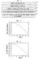
- An alternative is the two-parameter search procedure of FIG. 3, in which both u -vectors and the initial matrix are varied. (However, we have found that in general, performance is more sensitive to the choice of u than it is to the choice of ⁇ 1 .)
- FIG. 3 illustrates an exemplary two-parameter search at a high level.
- a set of initial matrices is generated at block 70, and a set of random u -vectors is generated, as before, at block 75.
- a constellation of signal matrices is generated for each possible pairing of an initial matrix with a u -vector.
- the maximum error-probability measure is determined for each of these constellations.
- an optimal constellation is chosen. As before, the optimal constellation is that constellation whose maximum error-probability measure is the smallest.
- the matrix described above has all zeroes for the entries in the last T-M rows. In fact, we believe that it is also disadvantageous to use for the initial signal matrix any matrix having T - M rows of all zeroes.
- a Discrete Fourier Transform (DFT) matrix is a square matrix, having T orthonormal columns, in which the rs -th element ( r is the row index and s is the column index) is given by e t 2 ⁇ T ( r -1)( s -1) ⁇ 1 T .
- the initial signal matrix is constructed by selecting M of the T columns of a DFT matrix. Such a selection may be made randomly, for example.
- the initial signal matrix is constructed as a random-valued orthonormal matrix.
- procedures are readily available for generating a T ⁇ M matrix X whose elements are T ⁇ M independent complex variables, Gaussian-distributed with 0 mean and unit variance.
- QR factorization A well-known procedure referred to as "QR factorization" is performed on this matrix.
- the initial signal matrix is set equal to Q .
- a signal constellation or an initial signal matrix is newly chosen or newly generated at the transmitting location, information sufficient to specify such constellation or matrix is then advantageously transmitted to the receiving location for use in the receiver.
- the signal constellation or initial signal matrix may be chosen or generated at the receiving location, and transmitted to the sending location for use in the transmitter.
- the signal constellation may be stored at the site where signals are generated for transmission, or at a location accessible to it.
- the signal matrices may be generated, as needed, at such a site or location.
- the signal matrices are also used, at the receiving end, for recovering the transmitted signal from the received signal.
- the signal constellation may be stored where it will be accessible, or it may be generated as needed.
- a USTM signal constellation of certain specific kinds we have described here may be characterized in various ways: e.g., as a subset of a set of signal matrices having a circulant correlation structure, or as a set of signal matrices related to each other via repeated multiplications of a common initial signal matrix by one or more unitary matrices.
- FIG. 4 shows the block error rate (i.e., the probability of falsely identifying a received signal matrix)
- FIG. 5 shows the bit error rate that we obtained, both at a data rate of one bit per channel use. It is evident that the bit error rate drops steeply as the signal-to-noise ratio ⁇ is increased. This is consistent with our theoretical prediction that USTM signals are asymptotically optimal for large signal-to-noise ratios.
Landscapes
- Engineering & Computer Science (AREA)
- Computer Networks & Wireless Communication (AREA)
- Signal Processing (AREA)
- Radio Transmission System (AREA)
- Digital Transmission Methods That Use Modulated Carrier Waves (AREA)
- Variable-Direction Aerials And Aerial Arrays (AREA)
- Noise Elimination (AREA)
- Mobile Radio Communication Systems (AREA)
Claims (33)
- Verfahren zur drahtlosen Kommunikation mit den folgenden Schritten: Erzeugen einer Vielzahl von Basisbandsignalen (10), Aufmodulieren der Signale auf einen Träger, wodurch eine Sequenz von Signalen der Trägerebene gebildet wird, und Übertragen der Signalsequenz auf Trägerebene von einem Array von zwei oder mehr Antennen, wobei:jedes Basisbandsignal eine oder mehrere zeitliche Sequenzen komplexer Amplituden umfaßt, wobei jede Sequenz von einer jeweiligen Antenne des Arrays gesendet werden soll;jedes Basisbandsignal als eine Übertragungsmatrix darstellbar ist, in der jede Spalte eine jeweilige Antenne und jede Zeile ein jeweiliges Zeitsegment darstellt;jede Übertragungsmatrix proportional zu einer jeweiligen Matrix mit orthogonalen Spalten ist, wobei die Matrizen orthonormale Spalten aufweisen, die als USTM-Matrizen bezeichnet werden sollen;der Erzeugungsschritt das Erzeugen einer Vielzahl von Übertragungsmatrizen umfaßt, die proportional zu jeweiligen USTM-Matrizen sind, wobei der Erzeugungsschritt dadurch gekennzeichnet ist, daßfür jede gegebene Übertragungsmatrix der erzeugten Vielzahl die entsprechende USTM-Matrix entweder eine gemeinsame Anfangsmatrix oder ein Produkt von einer oder mehreren Multiplikationen der gemeinsamen Anfangsmatrix mit einer oder mehreren unitären Matrizen oder eine Matrix ist, die aus einer Matrix einer der obenerwähnten Typen durch Multiplikation mit einer weiteren unitären Matrix abgeleitet wird.
- Verfahren nach Anspruch 1, wobei bei dem Erzeugungsschritt weiterhin die USTM-Matrix ausgewählt wird, die jeder Übertragungsmatrix entspricht.
- Verfahren nach Anspruch 1, wobei bei dem Erzeugungsschritt weiterhin die USTM-Matrix erzeugt wird (25-65), die jeder Übertragungsmatrix entspricht.
- Verfahren nach Anspruch 1, bei dem weiterhin die gemeinsame Anfangsmatrix ausgewählt und eine Beschreibung der gewählten gemeinsamen Anfangsmatrix zu einem Empfänger übertragen wird.
- Verfahren zur drahtlosen Kommunikation, bei dem eine Signalsequenz auf Trägerebene von einem Array von einer oder mehreren Empfangsantennen als Reaktion auf eine Übertragung empfangen und die Sequenz demoduliert wird, wodurch eine Vielzahl von Basisbandsignalen erzeugt wird, wobei
jedes Basisbandsignal eine oder mehrere zeitliche Sequenzen komplexer Amplituden umfaßt, wobei jede Sequenz von einer jeweiligen Antenne des Arrays empfangen wird;
jedes Basisbandsignal als ein Vektor oder eine Matrix darstellbar ist, worin jede Spalte eine jeweilige Antenne und jede Zeile ein jeweiliges Zeitsegment darstellt;
bei dem Verfahren weiterhin jedem empfangenen Vektor oder jeder empfangenen Matrix eine Signalmatrix zugeschrieben wird, die einer bekannten Konstellation von Signalmatrizen angehört, die als USTM-Matrizen bezeichnet werden sollen und orthonormale Spalten aufweisen;
für jeden empfangenen Vektor oder jede empfangene Matrix der Schritt des Zuschreibens folgendes umfaßt: Vergleichen des empfangenen Vektors oder der empfangenen Matrix mit jeder USTM-Matrix der Konstellation, um dadurch eine Wahrscheinlichkeitsbewertung auszuwerten, und Wählen derjenigen USTM-Matrix für die Zuschreibung, die die größte Wahrscheinlichkeitsbewertung ergibt; und
der Schritt des Zuschreibens dadurch gekennzeichnet ist, daß jede USTM-Matrix der Konstellation entweder eine gemeinsame Anfangsmatrix oder ein Produkt von einer oder mehreren Multiplikationen der gemeinsamen Anfangsmatrix mit einer oder mehreren unitären Matrizen oder eine Matrix ist, die aus einer Matrix einer der obenerwähnten Typen durch Multiplikation mit einer weiteren unitären Matrix abgeleitet wird. - Verfahren nach Anspruch 5, bei dem weiterhin die Konstellation von USTM-Matrizen erzeugt wird.
- Verfahren nach Anspruch 3 oder Anspruch 6, wobei zur Erzeugung von USTM-Matrizen durch wiederholte Multiplikationen nur eine unitäre Matrix verwendet wird, wobei die unitäre Matrix als eine Generatormatrix bezeichnet werden soll.
- Verfahren nach Anspruch 7, wobei die Generatormatrix eine L-te Wurzel einer Identitätsmatrix ist, wobei L eine positive ganze Zahl ist.
- Verfahren nach Anspruch 8, wobei die Konstellation einen Teil der L möglichen USTM-Matrizen, die durch die Generatormatrix erzeugt werden können, aber nicht alle diese Matrizen enthält.
- Verfahren nach Anspruch 3 oder Anspruch 6, wobei zwei oder mehr unitäre Matrizen zur Erzeugung von USTM-Matrizen durch wiederholte Multiplikationen verwendet werden, wobei die unitären Matrizen als Generatormatrizen bezeichnet werden sollen.
- Verfahren nach Anspruch 10, wobei: es K Generatormatrizen gibt, wobei K eine positive ganze Zahl größer als 1 ist; jede Generatormatrix eine L k -te Wurzel einer Identitätsmatrix mit k = 1, . . . , K ist; und jedes L k verschieden ist.
- Verfahren nach Anspruch 11, wobei die Konstellation einen Teil der L1x. . .x L k möglichen USTM-Matrizen, die durch die Generatormatrizen erzeugt werden können, aber nicht alle diese Matrizen enthält.
- Verfahren nach Anspruch 1 oder Anspruch 6, bei dem weiterhin die gemeinsame Anfangsmatrix ausgewählt wird.
- Verfahren nach Anspruch 13, wobei die Auswahl der gemeinsamen Matrix durch Auswählen von Spalten einer quadratischen Matrix mit T orthonormalen Spalten der als eine Diskrete Fourier-Transformationsmatrix bezeichneten Art ausgeführt wird, wobei bei einem gegebenen Zeilenindex r und einem gegebenen Spaltenindex s das rs-te Element durch
- Verfahren nach Anspruch 13, wobei die Auswahl der gemeinsamen Matrix durch Erzeugen einer Matrix mit zufallswertigen komplexen Koeffizienten und durch Durchführen einer QR-Faktorisierung an der Matrix ausgeführt wird.
- Verfahren nach Anspruch 13, bei dem weiterhin eine Beschreibung der gewählten gemeinsamen Anfangsmatrix zu einer Station übertragen wird, deren Signale empfangen werden sollen.
- Verfahren nach Anspruch 3 oder Anspruch 6, wobei der Erzeugungsschritt das Erzeugen einer Teilmenge einer Menge von USTM-Matrizen Φl mit einer Struktur umfaßt, die als eine zirkulante Korrelationsstruktur bezeichnet wird, bei der es eine Matrix Θ gibt, die der Klasse der, -ten Wurzeln der Identitätsmatrix α, β, γ, δ angehört und l positive Indizes sind, jede Signalmatrix Φl das Ergebnis von l-1 Multiplikationen einer Anfangsmatrix mit Θ ist und für alle α, β, γ, δ, wenn[α-β)mod

- Verfahren zur drahtlosen Kommunikation mit den folgenden Schritten: Erzeugen einer Vielzahl von Basisbandsignalen (10), Aufmodulieren der Signale auf einen Träger, wodurch eine Sequenz von Signalen der Trägerebene gebildet wird, und Übertragen der Signalsequenz auf Trägerebene von einer Antenne wobei:jedes Basisbandsignal eine zeitliche Sequenz komplexer Amplituden umfaßt, wobei die Sequenz von der Antenne übertragen werden soll;jdes Basisbandsignal als ein Übertragungsvektor darstellbar ist, in dem jede Zeile ein jeweiliges Zeitsegment darstellt;jeder Übertragungsvektor proportional zu einem jeweiligen einheitsnormierten Vektor ist, der als ein USTM-Vektor bezeichnet werden soll; undder Erzeugungsschritt das Erzeugen einer Vielzahl von Übertragungsvektoren umfaßt, die proportional zu jeweiligen USTM-Vektoren sind, wobei der Erzeugungsschritt dadurch gekennzeichnet ist, daßfür jeden gegebenen Übertragungsvektor der erzeugten Vielzahl der entsprechende USTM-Vektor entweder ein gemeinsamer Anfangsvektor oder ein Produkt von einer oder mehreren Multiplikationen des gemeinsamen Anfangsvektors mit einer oder mehreren unitären Matrizen oder ein Vektor ist, der aus einem Vektor einer der obenerwähnten Typen durch Multiplikation mit einer weiteren unitären Matrix abgeleitet wird.
- Verfahren nach Anspruch 18, wobei der Erzeugungsschritt weiterhin das Auswählen des USTM-Vektors, der jedem Übertragungsvektor entspricht, umfaßt.
- Verfahren nach Anspruch 18, wobei der Erzeugungsschritt weiterhin das Erzeugen (25-65) des USTM-Vektors, der jedem Übertragungsvektor entspricht, umfaßt.
- Verfahren nach Anspruch 20, wobei zur Erzeugung von USTM-Vektoren durch wiederholte Multiplikationen nur eine unitäre Matrix verwendet wird, wobei die unitäre Matrix als eine Generatormatrix bezeichnet werden soll; wobei die Generatormatrix eine L-te Wurzel einer Identitätsmatrix ist, wobei L eine positive ganze Zahl ist; und die Basisbandsignale aus einem Teil von L möglichen USTM-Vektoren, die durch die Generatormatrix gebildet werden können, aber nicht allen diesen Vektoren bestehen.
- Verfahren nach Anspruch 18, bei dem weiterhin der gemeinsame Anfangsvektor ausgewählt und eine Beschreibung des gewählten gemeinsamen Anfangsvektors zu einem Empfänger übertragen wird.
- Verfahren zur drahtlosen Kommunikation, bei dem eine Signalsequenz auf Trägerebene von einem Array von einer oder mehreren Empfangsantennen als Reaktion auf eine Übertragung empfangen und die Sequenz demoduliert wird, wodurch eine Vielzahl von Basisbandsignalen erzeugt wird, wobei
jedes Basisbandsignal eine oder mehrere zeitliche Sequenzen komplexer Amplituden umfaßt, wobei jede Sequenz von einer jeweiligen Antenne des Arrays empfangen wird;
jedes Basisbandsignal als ein Vektor oder eine Matrix darstellbar ist, worin jede Spalte eine jeweilige Antenne und jede Zeile ein jeweiliges Zeitsegment darstellt;
bei dem Verfahren weiterhin jedem empfangenen Vektor oder jeder empfangenen Matrix ein Signalvektor zugeschrieben wird, der einer bekannten Konstellation von einheitsnormierten Signalvektoren, die als USTM-Vektoren bezeichnet werden sollen, angehört;
für jeden empfangenen Vektor oder jede empfangene Matrix der Schritt des Zuschreibens folgendes umfaßt: Vergleichen des empfangenen Vektors oder empfangenen Matrix mit jedem USTM-Vektor der Konstellation, wodurch eine Wahrscheinlichkeitsbewertung ausgewertet wird, und Wählen desjenigen USTM-Vektors für die Zuschreibung, der die größte Wahrscheinlichkeitsbewertung ergibt; und
der Schritt des Zuschreibens dadurch gekennzeichnet ist, daß jeder USTM-Vektor der Konstellation entweder ein gemeinsamer Anfangsvektor oder ein Produkt von einer oder mehreren Multiplikationen des gemeinsamen Anfangsvektors mit einer oder mehreren unitären Matrizen oder ein Vektor ist, der aus einem Vektor einer der obenerwähnten Typen durch Multiplikation mit einer weiteren unitären Matrix abgeleitet wird. - Verfahren nach Anspruch 23, bei dem weiterhin die Konstellation von USTM-Vektoren erzeugt wird.
- Verfahren nach Anspruch 20 oder Anspruch 24, wobei zur Erzeugung von USTM-Vektoren durch wiederholte Multiplikationen nur eine unitäre Matrix verwendet wird, wobei die unitäre Matrix als eine Generatormatrix bezeichnet werden soll.
- Verfahren nach Anspruch 25, wobei die Generatormatrix eine L-te Wurzel einer Identitätsmatrix ist, wobei L eine positive ganze Zahl ist.
- Verfahren nach Anspruch 26, wobei die Konstellation einen Teil von L möglichen USTM-Vektoren, die durch die Generatormatrix erzeugt werden können, aber nicht alle diese Vektoren enthält.
- Verfahren nach Anspruch 20 oder Anspruch 24, wobei zwei oder mehr unitäre Matrizen zur Erzeugung von USTM-Vektoren durch wiederholte Multiplikationen verwendet werden, wobei die unitären Matrizen als Generatormatrizen bezeichnet werden sollen.
- Verfahren nach Anspruch 28, wobei: es K Generatormatrizen gibt, wobei K eine positive ganze Zahl größer als 1 ist; jede Generatormatrix eine L k -te Wurzel einer Identitätsmatrix mit k = 1, . . ., K ist; und jedes L k verschieden ist.
- Verfahren nach Anspruch 29, wobei die Konstellation einen Teil der L1x. . .x L k möglichen USTM-Vektoren, die durch die Generatormatrizen erzeugt werden können, aber nicht alle diese Vektoren enthält.
- Verfahren nach Anspruch 18 oder Anspruch 23, bei dem weiterhin der gemeinsame Anfangsvektor ausgewählt wird.
- Verfahren nach Anspruch 31, wobei die Auswahl des gemeinsamen Vektors durch Auswählen einer Spalte einer quadratischen Matrix mit T orthonormalen Spalten der als eine Diskrete Fourier-Transformationsmatrix bezeichneten Art ausgeführt wird, wobei bei einem gegebenen Zeilenindex r und einem gegebenen Spaltenindex s das rs-te Element durch
- Verfahren nach Anspruch 31, bei dem weiterhin eine Beschreibung des gewählten gemeinsamen Anfangsvektors zu einer Station übertragen wird, deren Signale empfangen werden sollen.
Applications Claiming Priority (2)
| Application Number | Priority Date | Filing Date | Title |
|---|---|---|---|
| US09/206,843 US6363121B1 (en) | 1998-12-07 | 1998-12-07 | Wireless transmission method for antenna arrays using unitary space-time signals |
| US206843 | 1998-12-07 |
Publications (3)
| Publication Number | Publication Date |
|---|---|
| EP1009124A2 EP1009124A2 (de) | 2000-06-14 |
| EP1009124A3 EP1009124A3 (de) | 2000-08-09 |
| EP1009124B1 true EP1009124B1 (de) | 2002-12-04 |
Family
ID=22768207
Family Applications (1)
| Application Number | Title | Priority Date | Filing Date |
|---|---|---|---|
| EP99309613A Expired - Lifetime EP1009124B1 (de) | 1998-12-07 | 1999-11-30 | Verfahren zur drahtlosen Übertragung über ein Antennennetz unter Verwendung unitärer Raum-Zeit-Signale |
Country Status (5)
| Country | Link |
|---|---|
| US (1) | US6363121B1 (de) |
| EP (1) | EP1009124B1 (de) |
| JP (1) | JP3604981B2 (de) |
| CA (1) | CA2287759C (de) |
| DE (1) | DE69904284T2 (de) |
Cited By (3)
| Publication number | Priority date | Publication date | Assignee | Title |
|---|---|---|---|---|
| US7978778B2 (en) | 2004-09-03 | 2011-07-12 | Qualcomm, Incorporated | Receiver structures for spatial spreading with space-time or space-frequency transmit diversity |
| CN1918839B (zh) * | 2003-12-17 | 2012-05-02 | 高通股份有限公司 | 多天线通信系统中的空间扩频 |
| TWI426724B (zh) * | 2003-09-09 | 2014-02-11 | Qualcomm Inc | 用於在多入多出通信系統中發送遞增冗餘傳送之方法及設備 |
Families Citing this family (39)
| Publication number | Priority date | Publication date | Assignee | Title |
|---|---|---|---|---|
| US7864902B1 (en) * | 2003-04-28 | 2011-01-04 | At&T Corp. | Differential transmitter diversity technique for wireless communications |
| US6891903B2 (en) * | 1999-04-22 | 2005-05-10 | At&T Corp. | Multiple transmit antenna differential detection from generalized orthogonal designs |
| US6724842B1 (en) * | 1999-07-16 | 2004-04-20 | Lucent Technologies Inc. | Method for wireless differential communication using multiple transmitter antennas |
| US6693976B1 (en) * | 2000-03-21 | 2004-02-17 | Lucent Technologies Inc. | Method of wireless communication using structured unitary space-time signal constellations |
| AT410738B (de) * | 2001-05-04 | 2003-07-25 | Artes Harold Dipl Ing | Verfahren zum übertragen von datenströmen sowie sende- und empfangseinrichtung hiefür |
| KR100541284B1 (ko) * | 2002-03-21 | 2006-01-10 | 엘지전자 주식회사 | 다중 입출력 이동 통신 시스템에서의 신호 처리 방법 |
| FR2848747A1 (fr) * | 2002-12-16 | 2004-06-18 | France Telecom | Procede et dispositif multi-antenne de transmission de signaux |
| US20040192216A1 (en) * | 2003-03-31 | 2004-09-30 | Marzetta Thomas Louis | Training for MIMO communication systems |
| US7508808B2 (en) * | 2003-05-14 | 2009-03-24 | Alcatel-Lucent Usa Inc. | Frequency-division multiplexing system and method for communication having enhanced reliability in fading environments |
| DE60335666D1 (de) * | 2003-08-29 | 2011-02-17 | Nat Inst Inf & Comm Tech | Sendervorrichtung, empfängervorrichtung, sendeverfahren, empfangsverfahren und programm |
| FR2860666A1 (fr) * | 2003-10-03 | 2005-04-08 | France Telecom | Procede d'emission multi-antennes d'un signal par codes espaces-temps en bloc, procede de recuperation et signal correspondant |
| US7302009B2 (en) * | 2003-12-17 | 2007-11-27 | Qualcomm Incorporated | Broadcast transmission with spatial spreading in a multi-antenna communication system |
| TWI394396B (zh) * | 2003-12-17 | 2013-04-21 | Qualcomm Inc | 在一多天線通信系統中的空間擴張 |
| US7633850B2 (en) * | 2003-12-18 | 2009-12-15 | National Institute Of Information And Communications Technology | Transmitter, receiver, transmitting method, receiving method, and program |
| GB2409617B (en) * | 2003-12-23 | 2006-07-12 | Toshiba Res Europ Ltd | Data encoding for static mimo channels |
| US7194042B2 (en) * | 2004-01-13 | 2007-03-20 | Qualcomm Incorporated | Data transmission with spatial spreading in a mimo communication system |
| US7336746B2 (en) | 2004-12-09 | 2008-02-26 | Qualcomm Incorporated | Data transmission with spatial spreading in a MIMO communication system |
| US8169889B2 (en) | 2004-02-18 | 2012-05-01 | Qualcomm Incorporated | Transmit diversity and spatial spreading for an OFDM-based multi-antenna communication system |
| US7346115B2 (en) * | 2004-04-22 | 2008-03-18 | Qualcomm Incorporated | Iterative eigenvector computation for a MIMO communication system |
| US8923785B2 (en) | 2004-05-07 | 2014-12-30 | Qualcomm Incorporated | Continuous beamforming for a MIMO-OFDM system |
| US8285226B2 (en) | 2004-05-07 | 2012-10-09 | Qualcomm Incorporated | Steering diversity for an OFDM-based multi-antenna communication system |
| US7110463B2 (en) | 2004-06-30 | 2006-09-19 | Qualcomm, Incorporated | Efficient computation of spatial filter matrices for steering transmit diversity in a MIMO communication system |
| CN1294714C (zh) * | 2004-07-15 | 2007-01-10 | 上海交通大学 | 适用于快速衰落信道的星座分割差分空时调制解调方法 |
| US7978649B2 (en) | 2004-07-15 | 2011-07-12 | Qualcomm, Incorporated | Unified MIMO transmission and reception |
| US7894548B2 (en) | 2004-09-03 | 2011-02-22 | Qualcomm Incorporated | Spatial spreading with space-time and space-frequency transmit diversity schemes for a wireless communication system |
| KR100913873B1 (ko) * | 2004-09-13 | 2009-08-26 | 삼성전자주식회사 | 고속 전송률을 가지는 차등 시공간 블록 부호 장치 및 방법 |
| US8340216B2 (en) | 2005-03-18 | 2012-12-25 | Qualcomm Incorporated | Space-time scrambling for cellular systems |
| TWI347102B (en) * | 2005-03-18 | 2011-08-11 | Qualcomm Inc | Space-time scrambling for cellular systems |
| US8543070B2 (en) | 2006-04-24 | 2013-09-24 | Qualcomm Incorporated | Reduced complexity beam-steered MIMO OFDM system |
| US8290089B2 (en) | 2006-05-22 | 2012-10-16 | Qualcomm Incorporated | Derivation and feedback of transmit steering matrix |
| US8184732B2 (en) * | 2007-05-01 | 2012-05-22 | Broadcom Corporation | Method and system for codebook design for pre-coding techniques |
| WO2008156700A2 (en) * | 2007-06-15 | 2008-12-24 | Worcester Polytechnic Institute | Precision location methods and systems |
| CN110087317B (zh) | 2007-09-28 | 2021-01-05 | 无线创新信号信任公司 | Wtru、wtru执行的方法、基站执行的方法以及装置 |
| KR20160140967A (ko) | 2008-01-02 | 2016-12-07 | 시그널 트러스트 포 와이어리스 이노베이션 | 셀 재선택을 위한 방법 및 장치 |
| JP5553318B2 (ja) * | 2008-07-08 | 2014-07-16 | コーニンクレッカ フィリップス エヌ ヴェ | Led照明ユニットの相対的位置を決定するための方法及び装置 |
| US8594215B2 (en) * | 2010-06-11 | 2013-11-26 | Alcatel Lucent | MIMO system having a plurality of service antennas for data transmission thereof |
| JP5663284B2 (ja) * | 2010-12-06 | 2015-02-04 | 東芝テック株式会社 | アンテナ切替システム |
| JP5787527B2 (ja) * | 2011-01-18 | 2015-09-30 | キヤノン株式会社 | 信号処理回路及び超音波診断装置 |
| US9264118B1 (en) | 2015-03-02 | 2016-02-16 | Mitsubishi Electric Research Laboratories, Inc. | System and method for communicating data symbols via wireless doubly-selective channels |
Family Cites Families (3)
| Publication number | Priority date | Publication date | Assignee | Title |
|---|---|---|---|---|
| US6097771A (en) * | 1996-07-01 | 2000-08-01 | Lucent Technologies Inc. | Wireless communications system having a layered space-time architecture employing multi-element antennas |
| US6058105A (en) * | 1997-09-26 | 2000-05-02 | Lucent Technologies Inc. | Multiple antenna communication system and method thereof |
| US6088408A (en) * | 1998-11-06 | 2000-07-11 | At & T Corp. | Decoding for generalized orthogonal designs for space-time codes for wireless communication |
-
1998
- 1998-12-07 US US09/206,843 patent/US6363121B1/en not_active Expired - Lifetime
-
1999
- 1999-10-29 CA CA002287759A patent/CA2287759C/en not_active Expired - Fee Related
- 1999-11-30 EP EP99309613A patent/EP1009124B1/de not_active Expired - Lifetime
- 1999-11-30 DE DE69904284T patent/DE69904284T2/de not_active Expired - Lifetime
- 1999-12-06 JP JP34688499A patent/JP3604981B2/ja not_active Expired - Fee Related
Cited By (5)
| Publication number | Priority date | Publication date | Assignee | Title |
|---|---|---|---|---|
| TWI426724B (zh) * | 2003-09-09 | 2014-02-11 | Qualcomm Inc | 用於在多入多出通信系統中發送遞增冗餘傳送之方法及設備 |
| US8908496B2 (en) | 2003-09-09 | 2014-12-09 | Qualcomm Incorporated | Incremental redundancy transmission in a MIMO communication system |
| CN1918839B (zh) * | 2003-12-17 | 2012-05-02 | 高通股份有限公司 | 多天线通信系统中的空间扩频 |
| US8204149B2 (en) | 2003-12-17 | 2012-06-19 | Qualcomm Incorporated | Spatial spreading in a multi-antenna communication system |
| US7978778B2 (en) | 2004-09-03 | 2011-07-12 | Qualcomm, Incorporated | Receiver structures for spatial spreading with space-time or space-frequency transmit diversity |
Also Published As
| Publication number | Publication date |
|---|---|
| EP1009124A2 (de) | 2000-06-14 |
| US6363121B1 (en) | 2002-03-26 |
| JP2000232385A (ja) | 2000-08-22 |
| JP3604981B2 (ja) | 2004-12-22 |
| CA2287759A1 (en) | 2000-06-07 |
| CA2287759C (en) | 2003-07-29 |
| EP1009124A3 (de) | 2000-08-09 |
| DE69904284D1 (de) | 2003-01-16 |
| DE69904284T2 (de) | 2003-08-28 |
Similar Documents
| Publication | Publication Date | Title |
|---|---|---|
| US6363121B1 (en) | Wireless transmission method for antenna arrays using unitary space-time signals | |
| CA2275520C (en) | Wireless transmission method for antenna arrays, having improved resistance to fading | |
| CN1878159B (zh) | 通过至少一个通信信道传送符号的方法 | |
| EP1863192A1 (de) | Verfahren zur begrenzungsrückkopplung für ein mehrantennensystem, verfahren zur kanalparametererzeugung und funkempfänger | |
| KR101999452B1 (ko) | 서브-블록 디코딩 데이터 신호를 위한 방법 및 장치 | |
| CN107094063B (zh) | 半穷举迭代块解码方法和设备 | |
| US20060039497A1 (en) | Linear precoding for multi-input systems based on channel estimate and channel statistics | |
| EP1069723B1 (de) | Verfahren zur drahtlosen differentiellen Kommunikation mit mehreren Sendeantennen | |
| KR20080059014A (ko) | 다중 입출력 무선통신 시스템에서 수신 장치 및 방법 | |
| KR20180026381A (ko) | 통신 시스템용 시공간 코딩 | |
| JP4652333B2 (ja) | ユニタリ時空符号による信号のマルチアンテナ送信方法、受信方法および対応する信号 | |
| US11115240B2 (en) | Methods, apparatuses, and systems for performing analog CSI feedback | |
| US6944236B2 (en) | Method of multiple-antenna wireless communication using space-time codes | |
| KR20180090956A (ko) | 데이터 신호를 서브-블록 디코딩하기 위한 방법 및 장치 | |
| US20060056529A1 (en) | Method and system for optimization of channel estimation and synchronization in an OFDM-MIMO wireless communication system | |
| CN101667860B (zh) | 在多天线数字无线通信系统中检测信号的方法 | |
| US20020163892A1 (en) | Cayley-encodation of unitary matrices for differential communication | |
| US6693976B1 (en) | Method of wireless communication using structured unitary space-time signal constellations | |
| US20100232479A1 (en) | Wireless transceiver | |
| Annamalai et al. | A moment-generating function (MGF) derivative-based unified analysis of incoherent diversity reception of M-ary orthogonal signals over independent and correlated fading channels | |
| Sergienko et al. | Combining Index Modulation with Codebooks for Noncoherent Reception | |
| EP3378168B1 (de) | Vorrichtung und verfahren zum ableiten einer submatrix | |
| Li et al. | Diversity analysis of MIMO-OTFS in multipath rapid fading channels | |
| Diao et al. | Constellation Optimization Based on DDPG for Cayley Differential Unitary Space-Time Code | |
| CN103840919B (zh) | 分布式多天线系统中的预编码方法和装置 |
Legal Events
| Date | Code | Title | Description |
|---|---|---|---|
| PUAI | Public reference made under article 153(3) epc to a published international application that has entered the european phase |
Free format text: ORIGINAL CODE: 0009012 |
|
| 17P | Request for examination filed |
Effective date: 19991215 |
|
| AK | Designated contracting states |
Kind code of ref document: A2 Designated state(s): DE FR |
|
| AX | Request for extension of the european patent |
Free format text: AL;LT;LV;MK;RO;SI |
|
| PUAL | Search report despatched |
Free format text: ORIGINAL CODE: 0009013 |
|
| RIC1 | Information provided on ipc code assigned before grant |
Free format text: 7H 04L 1/06 A, 7H 04B 7/06 B |
|
| AK | Designated contracting states |
Kind code of ref document: A3 Designated state(s): AT BE CH CY DE DK ES FI FR GB GR IE IT LI LU MC NL PT SE |
|
| AX | Request for extension of the european patent |
Free format text: AL;LT;LV;MK;RO;SI |
|
| 17Q | First examination report despatched |
Effective date: 20000908 |
|
| AKX | Designation fees paid |
Free format text: DE FR |
|
| GRAG | Despatch of communication of intention to grant |
Free format text: ORIGINAL CODE: EPIDOS AGRA |
|
| GRAG | Despatch of communication of intention to grant |
Free format text: ORIGINAL CODE: EPIDOS AGRA |
|
| GRAH | Despatch of communication of intention to grant a patent |
Free format text: ORIGINAL CODE: EPIDOS IGRA |
|
| GRAH | Despatch of communication of intention to grant a patent |
Free format text: ORIGINAL CODE: EPIDOS IGRA |
|
| GRAA | (expected) grant |
Free format text: ORIGINAL CODE: 0009210 |
|
| AK | Designated contracting states |
Kind code of ref document: B1 Designated state(s): DE FR |
|
| REF | Corresponds to: |
Ref document number: 69904284 Country of ref document: DE Date of ref document: 20030116 |
|
| ET | Fr: translation filed | ||
| PLBE | No opposition filed within time limit |
Free format text: ORIGINAL CODE: 0009261 |
|
| STAA | Information on the status of an ep patent application or granted ep patent |
Free format text: STATUS: NO OPPOSITION FILED WITHIN TIME LIMIT |
|
| 26N | No opposition filed |
Effective date: 20030905 |
|
| REG | Reference to a national code |
Ref country code: FR Ref legal event code: CD Owner name: ALCATEL-LUCENT USA INC. Effective date: 20131122 |
|
| REG | Reference to a national code |
Ref country code: FR Ref legal event code: GC Effective date: 20140410 |
|
| REG | Reference to a national code |
Ref country code: FR Ref legal event code: RG Effective date: 20141015 |
|
| REG | Reference to a national code |
Ref country code: FR Ref legal event code: PLFP Year of fee payment: 17 |
|
| REG | Reference to a national code |
Ref country code: FR Ref legal event code: PLFP Year of fee payment: 18 |
|
| PGFP | Annual fee paid to national office [announced via postgrant information from national office to epo] |
Ref country code: FR Payment date: 20161118 Year of fee payment: 18 Ref country code: DE Payment date: 20161121 Year of fee payment: 18 |
|
| REG | Reference to a national code |
Ref country code: DE Ref legal event code: R119 Ref document number: 69904284 Country of ref document: DE |
|
| REG | Reference to a national code |
Ref country code: FR Ref legal event code: ST Effective date: 20180731 |
|
| PG25 | Lapsed in a contracting state [announced via postgrant information from national office to epo] |
Ref country code: DE Free format text: LAPSE BECAUSE OF NON-PAYMENT OF DUE FEES Effective date: 20180602 Ref country code: FR Free format text: LAPSE BECAUSE OF NON-PAYMENT OF DUE FEES Effective date: 20171130 |
|
| REG | Reference to a national code |
Ref country code: DE Ref legal event code: R081 Ref document number: 69904284 Country of ref document: DE Owner name: WSOU INVESTMENTS, LLC, LOS ANGELES, US Free format text: FORMER OWNER: LUCENT TECHNOLOGIES INC., MURRAY HILL, N.J., US |