EP1009157A2 - Repérage de couleurs - Google Patents
Repérage de couleurs Download PDFInfo
- Publication number
- EP1009157A2 EP1009157A2 EP99309779A EP99309779A EP1009157A2 EP 1009157 A2 EP1009157 A2 EP 1009157A2 EP 99309779 A EP99309779 A EP 99309779A EP 99309779 A EP99309779 A EP 99309779A EP 1009157 A2 EP1009157 A2 EP 1009157A2
- Authority
- EP
- European Patent Office
- Prior art keywords
- photoreceptor
- lens
- polygon
- piezoelectric
- scan line
- Prior art date
- Legal status (The legal status is an assumption and is not a legal conclusion. Google has not performed a legal analysis and makes no representation as to the accuracy of the status listed.)
- Granted
Links
Images

Classifications
-
- H—ELECTRICITY
- H04—ELECTRIC COMMUNICATION TECHNIQUE
- H04N—PICTORIAL COMMUNICATION, e.g. TELEVISION
- H04N1/00—Scanning, transmission or reproduction of documents or the like, e.g. facsimile transmission; Details thereof
- H04N1/04—Scanning arrangements, i.e. arrangements for the displacement of active reading or reproducing elements relative to the original or reproducing medium, or vice versa
- H04N1/113—Scanning arrangements, i.e. arrangements for the displacement of active reading or reproducing elements relative to the original or reproducing medium, or vice versa using oscillating or rotating mirrors
- H04N1/1135—Scanning arrangements, i.e. arrangements for the displacement of active reading or reproducing elements relative to the original or reproducing medium, or vice versa using oscillating or rotating mirrors for the main-scan only
-
- H—ELECTRICITY
- H04—ELECTRIC COMMUNICATION TECHNIQUE
- H04N—PICTORIAL COMMUNICATION, e.g. TELEVISION
- H04N1/00—Scanning, transmission or reproduction of documents or the like, e.g. facsimile transmission; Details thereof
- H04N1/04—Scanning arrangements, i.e. arrangements for the displacement of active reading or reproducing elements relative to the original or reproducing medium, or vice versa
- H04N1/047—Detection, control or error compensation of scanning velocity or position
-
- H—ELECTRICITY
- H04—ELECTRIC COMMUNICATION TECHNIQUE
- H04N—PICTORIAL COMMUNICATION, e.g. TELEVISION
- H04N1/00—Scanning, transmission or reproduction of documents or the like, e.g. facsimile transmission; Details thereof
- H04N1/46—Colour picture communication systems
- H04N1/50—Picture reproducers
- H04N1/506—Reproducing the colour component signals picture-sequentially, e.g. with reproducing heads spaced apart from one another in the subscanning direction
-
- H—ELECTRICITY
- H04—ELECTRIC COMMUNICATION TECHNIQUE
- H04N—PICTORIAL COMMUNICATION, e.g. TELEVISION
- H04N1/00—Scanning, transmission or reproduction of documents or the like, e.g. facsimile transmission; Details thereof
- H04N1/04—Scanning arrangements, i.e. arrangements for the displacement of active reading or reproducing elements relative to the original or reproducing medium, or vice versa
- H04N1/12—Scanning arrangements, i.e. arrangements for the displacement of active reading or reproducing elements relative to the original or reproducing medium, or vice versa using the sheet-feed movement or the medium-advance or the drum-rotation movement as the slow scanning component, e.g. arrangements for the main-scanning
-
- H—ELECTRICITY
- H04—ELECTRIC COMMUNICATION TECHNIQUE
- H04N—PICTORIAL COMMUNICATION, e.g. TELEVISION
- H04N2201/00—Indexing scheme relating to scanning, transmission or reproduction of documents or the like, and to details thereof
- H04N2201/024—Indexing scheme relating to scanning, transmission or reproduction of documents or the like, and to details thereof deleted
- H04N2201/02406—Arrangements for positioning elements within a head
- H04N2201/02439—Positioning method
-
- H—ELECTRICITY
- H04—ELECTRIC COMMUNICATION TECHNIQUE
- H04N—PICTORIAL COMMUNICATION, e.g. TELEVISION
- H04N2201/00—Indexing scheme relating to scanning, transmission or reproduction of documents or the like, and to details thereof
- H04N2201/024—Indexing scheme relating to scanning, transmission or reproduction of documents or the like, and to details thereof deleted
- H04N2201/028—Indexing scheme relating to scanning, transmission or reproduction of documents or the like, and to details thereof deleted for picture information pick-up
- H04N2201/03—Indexing scheme relating to scanning, transmission or reproduction of documents or the like, and to details thereof deleted for picture information pick-up deleted
- H04N2201/031—Indexing scheme relating to scanning, transmission or reproduction of documents or the like, and to details thereof deleted for picture information pick-up deleted deleted
- H04N2201/03104—Integral pick-up heads, i.e. self-contained heads whose basic elements are a light source, a lens and a photodetector supported by a single-piece frame
- H04N2201/0315—Details of integral heads not otherwise provided for
- H04N2201/03154—Additional internal supporting or reinforcing member
-
- H—ELECTRICITY
- H04—ELECTRIC COMMUNICATION TECHNIQUE
- H04N—PICTORIAL COMMUNICATION, e.g. TELEVISION
- H04N2201/00—Indexing scheme relating to scanning, transmission or reproduction of documents or the like, and to details thereof
- H04N2201/04—Scanning arrangements
- H04N2201/047—Detection, control or error compensation of scanning velocity or position
- H04N2201/04701—Detection of scanning velocity or position
- H04N2201/0471—Detection of scanning velocity or position using dedicated detectors
-
- H—ELECTRICITY
- H04—ELECTRIC COMMUNICATION TECHNIQUE
- H04N—PICTORIAL COMMUNICATION, e.g. TELEVISION
- H04N2201/00—Indexing scheme relating to scanning, transmission or reproduction of documents or the like, and to details thereof
- H04N2201/04—Scanning arrangements
- H04N2201/047—Detection, control or error compensation of scanning velocity or position
- H04N2201/04701—Detection of scanning velocity or position
- H04N2201/04715—Detection of scanning velocity or position by detecting marks or the like, e.g. slits
- H04N2201/04722—Detection of scanning velocity or position by detecting marks or the like, e.g. slits on a photoconductive drum or belt
-
- H—ELECTRICITY
- H04—ELECTRIC COMMUNICATION TECHNIQUE
- H04N—PICTORIAL COMMUNICATION, e.g. TELEVISION
- H04N2201/00—Indexing scheme relating to scanning, transmission or reproduction of documents or the like, and to details thereof
- H04N2201/04—Scanning arrangements
- H04N2201/047—Detection, control or error compensation of scanning velocity or position
- H04N2201/04701—Detection of scanning velocity or position
- H04N2201/04729—Detection of scanning velocity or position in the main-scan direction
-
- H—ELECTRICITY
- H04—ELECTRIC COMMUNICATION TECHNIQUE
- H04N—PICTORIAL COMMUNICATION, e.g. TELEVISION
- H04N2201/00—Indexing scheme relating to scanning, transmission or reproduction of documents or the like, and to details thereof
- H04N2201/04—Scanning arrangements
- H04N2201/047—Detection, control or error compensation of scanning velocity or position
- H04N2201/04701—Detection of scanning velocity or position
- H04N2201/04731—Detection of scanning velocity or position in the sub-scan direction
-
- H—ELECTRICITY
- H04—ELECTRIC COMMUNICATION TECHNIQUE
- H04N—PICTORIAL COMMUNICATION, e.g. TELEVISION
- H04N2201/00—Indexing scheme relating to scanning, transmission or reproduction of documents or the like, and to details thereof
- H04N2201/04—Scanning arrangements
- H04N2201/047—Detection, control or error compensation of scanning velocity or position
- H04N2201/04701—Detection of scanning velocity or position
- H04N2201/04734—Detecting at frequent intervals, e.g. once per line for sub-scan control
-
- H—ELECTRICITY
- H04—ELECTRIC COMMUNICATION TECHNIQUE
- H04N—PICTORIAL COMMUNICATION, e.g. TELEVISION
- H04N2201/00—Indexing scheme relating to scanning, transmission or reproduction of documents or the like, and to details thereof
- H04N2201/04—Scanning arrangements
- H04N2201/047—Detection, control or error compensation of scanning velocity or position
- H04N2201/04701—Detection of scanning velocity or position
- H04N2201/04739—Detection of scanning velocity or position by detecting the scanning head or scanning carriage
-
- H—ELECTRICITY
- H04—ELECTRIC COMMUNICATION TECHNIQUE
- H04N—PICTORIAL COMMUNICATION, e.g. TELEVISION
- H04N2201/00—Indexing scheme relating to scanning, transmission or reproduction of documents or the like, and to details thereof
- H04N2201/04—Scanning arrangements
- H04N2201/047—Detection, control or error compensation of scanning velocity or position
- H04N2201/04701—Detection of scanning velocity or position
- H04N2201/04744—Detection of scanning velocity or position by detecting the scanned beam or a reference beam
-
- H—ELECTRICITY
- H04—ELECTRIC COMMUNICATION TECHNIQUE
- H04N—PICTORIAL COMMUNICATION, e.g. TELEVISION
- H04N2201/00—Indexing scheme relating to scanning, transmission or reproduction of documents or the like, and to details thereof
- H04N2201/04—Scanning arrangements
- H04N2201/047—Detection, control or error compensation of scanning velocity or position
- H04N2201/04753—Control or error compensation of scanning position or velocity
- H04N2201/04758—Control or error compensation of scanning position or velocity by controlling the position of the scanned image area
- H04N2201/0476—Control or error compensation of scanning position or velocity by controlling the position of the scanned image area using an optical, electro-optical or acousto-optical element
-
- H—ELECTRICITY
- H04—ELECTRIC COMMUNICATION TECHNIQUE
- H04N—PICTORIAL COMMUNICATION, e.g. TELEVISION
- H04N2201/00—Indexing scheme relating to scanning, transmission or reproduction of documents or the like, and to details thereof
- H04N2201/04—Scanning arrangements
- H04N2201/047—Detection, control or error compensation of scanning velocity or position
- H04N2201/04753—Control or error compensation of scanning position or velocity
- H04N2201/04758—Control or error compensation of scanning position or velocity by controlling the position of the scanned image area
- H04N2201/0476—Control or error compensation of scanning position or velocity by controlling the position of the scanned image area using an optical, electro-optical or acousto-optical element
- H04N2201/04763—Control or error compensation of scanning position or velocity by controlling the position of the scanned image area using an optical, electro-optical or acousto-optical element using a refracting element
-
- H—ELECTRICITY
- H04—ELECTRIC COMMUNICATION TECHNIQUE
- H04N—PICTORIAL COMMUNICATION, e.g. TELEVISION
- H04N2201/00—Indexing scheme relating to scanning, transmission or reproduction of documents or the like, and to details thereof
- H04N2201/04—Scanning arrangements
- H04N2201/047—Detection, control or error compensation of scanning velocity or position
- H04N2201/04753—Control or error compensation of scanning position or velocity
- H04N2201/04758—Control or error compensation of scanning position or velocity by controlling the position of the scanned image area
- H04N2201/04767—Control or error compensation of scanning position or velocity by controlling the position of the scanned image area by controlling the timing of the signals, e.g. by controlling the frequency o phase of the pixel clock
- H04N2201/04781—Controlling the phase of the signals
- H04N2201/04786—Controlling a start time, e.g. for output of a line of data
-
- H—ELECTRICITY
- H04—ELECTRIC COMMUNICATION TECHNIQUE
- H04N—PICTORIAL COMMUNICATION, e.g. TELEVISION
- H04N2201/00—Indexing scheme relating to scanning, transmission or reproduction of documents or the like, and to details thereof
- H04N2201/04—Scanning arrangements
- H04N2201/047—Detection, control or error compensation of scanning velocity or position
- H04N2201/04753—Control or error compensation of scanning position or velocity
- H04N2201/04789—Control or error compensation of scanning position or velocity in the main-scan direction
-
- H—ELECTRICITY
- H04—ELECTRIC COMMUNICATION TECHNIQUE
- H04N—PICTORIAL COMMUNICATION, e.g. TELEVISION
- H04N2201/00—Indexing scheme relating to scanning, transmission or reproduction of documents or the like, and to details thereof
- H04N2201/04—Scanning arrangements
- H04N2201/047—Detection, control or error compensation of scanning velocity or position
- H04N2201/04753—Control or error compensation of scanning position or velocity
- H04N2201/04791—Control or error compensation of scanning position or velocity in the sub-scan direction
-
- H—ELECTRICITY
- H04—ELECTRIC COMMUNICATION TECHNIQUE
- H04N—PICTORIAL COMMUNICATION, e.g. TELEVISION
- H04N2201/00—Indexing scheme relating to scanning, transmission or reproduction of documents or the like, and to details thereof
- H04N2201/04—Scanning arrangements
- H04N2201/047—Detection, control or error compensation of scanning velocity or position
- H04N2201/04753—Control or error compensation of scanning position or velocity
- H04N2201/04794—Varying the control or compensation during the scan, e.g. using continuous feedback or from line to line
Definitions
- This invention relates to electrophotographic color printers that use raster output scanners.
- it relates to the registration of color images in a single pass electrophotographic color printer by controlling the scan line positions using the raster output scanners.
- Electrophotographic marking is a well-known method of copying or printing documents. Electrophotographic marking is performed by exposing a light image representation of a desired final image onto a substantially uniformly charged photoreceptor. In response to that light image the photoreceptor discharges so as to produce an electrostatic latent image of the desired image on the photoreceptor's surface. Toner particles are then deposited onto that latent image so as to form a toner image. That toner image is then transferred from the photoreceptor onto a substrate such as a sheet of paper. The transferred toner image is then fused to the substrate, usually using heat and/or pressure. The surface of the photoreceptor is then cleaned of residual developing material and recharged in preparation for the production of another image.
- Electrophotographic marking can also produce color images by repeating the above process once for each color of toner that is used to make the composite color image.
- REaD IOI Recharge, Expose, and Develop, Image On Image
- a charged photoreceptive surface is exposed to a light image which represents a first color, say black.
- the resulting electrostatic latent image is then developed with black toner to produce a black toner image.
- the recharge, expose, and develop process is repeated for a second color, say yellow, then for a third color, say magenta, and finally for a fourth color, say cyan.
- the various latent images and consequently the color toners are placed in a superimposed registration such that a desired composite color image results. That composite color image is then transferred and fused onto a substrate.
- the REaD IOI process can be performed in a various ways. For example, in a single pass printer wherein the composite image is produced in a single pass of the photoreceptor through the machine. This requires a charging, an exposing, and a developing station for each color of toner. Single pass printers are advantageous in that they are relatively fast since a color image is produced during each cycle of the photoreceptor.
- a ROS is comprised of a laser light source (or sources) and a rotating polygon having a plurality of mirrored facets.
- the light source radiates a laser beam onto the polygon facets. That beam reflects from the facets and strikes the photoreceptor, producing a light spot.
- scan lines As the polygon rotates the spot traces lines, referred to as scan lines, on the photoreceptor.
- the direction of the sweeping spot is called the fast scan direction.
- By moving the photoreceptor perpendicular to the fast scan direction as the polygon rotates the spot raster scans the photoreceptor.
- the direction of motion of the photoreceptor is referred to either as the slow scan direction or the process direction.
- the laser beam is modulated to produce the desired latent image.
- misregistration Various factors cause misregistration. For example, photoreceptor motion may not be perfect because vibration, motor backlash, gear train interactions, mechanical imbalances, and/or friction, among other factors, can cause the instantaneous position of the photoreceptor to be less than ideal.
- Another cause of misregistration is polygon facet misplacement, also referred to as phasing errors. Facet misplacement comes about because it is very difficult to accurately synchronize the rotation of the polygon with the motion of the photoreceptor.
- the photoreceptor is in the proper position to receive the latent image the polygon facet that should reflect the laser beam might be ⁇ 1 ⁇ 2 a scan line off. The result is either a delay or an advance of the first scan line of a latent image, which causes the remaining scan lines to be offset.
- Misregistration in the fast scan direction is usually reduced by using a start-of-scan sensor in the optical path. That sensor detects when the sweeping spot is at a predetermined location. Using that information the modulation of the laser beam is controlled such that the latent image starts at the correct place on the photoreceptor.
- misregistration in the slow scan direction is harder to control.
- One approach is to accurately control the photoreceptor's motion. However, because of inertia, backlash, and other mechanical motion problems this is difficult and expensive to do. As previously noted, misregistration caused by phasing errors is also very difficult to control.
- US-A-5,287,125 discloses a raster output scanner that has process direction (slow scan direction) scan line position control.
- an error feedback circuit senses the position of a moving photoreceptor.
- Photoreceptor position errors are used to produce signals that are applied to a piezoelectric actuator.
- the piezoelectric actuator expands or contracts, moving a pre-polygon lens, which moves the scan line produced on the photoreceptor so as to correct for photoreceptor motion errors.
- EP-A-0928982 teaches a mirror moved by a piezoelectric element to correct for photoreceptor motion errors.
- a scan line adjustment technique capable of accurately adjusting the scan line position to correct for both photoreceptor position errors and for phasing errors, would be beneficial. Even more beneficial would be such a scan line adjustment technique that can be implemented at relatively low cost.
- the principles of the present invention provide for electrophotographic printers that have raster output scanners that adjust scan line positions to correct for photoreceptor position errors and for polygon facet phasing errors.
- An electrophotographic printers includes a moving photoreceptor, a photoreceptor position sensor for determining the position of the photoreceptor, and a raster output scanner that produces a sweeping laser beam in a scan line plane that images a scan line on the photoreceptor.
- the raster output scanner includes a laser for producing the laser beam, a pre-polygon lens for focusing that laser beam; and a rotating, multifaceted polygon for sweeping the laser beam in the scan plane.
- the raster output scanner further includes a facet position sensor that determines the position of the polygon facets and a scan line control mechanism for adjusting the scan line plane.
- the electrophotographic printer further includes a scan line position controller that receives photoreceptor position information from the photoreceptor position sensor and facet position information from the facet position sensor.
- the scan line position controller produces an electrical signal that drives the scan line control mechanism to adjust the scan line position such that the position of the scan line on the photoreceptor is compensated for errors in the position of the photoreceptor and for polygon facet errors.
- the scan line control mechanism is beneficially comprised of a mounting frame, a large displacement piezoelectric element attached to the mounting frame, and a flexible arm assembly having a lens mount that holds the pre-polygon lens.
- the flexible arm assembly includes flexible arms that can flex in the predominate direction of motion of the piezoelectric element, but that are substantially rigid in another direction and that resist rotation.
- the flexible arm assembly is mounted such that its flexible arms and the lens mount are biased toward the piezoelectric element. Electrical signals from the scan line position controller cause the piezoelectric element to expand and contract, which, combined with the bias of the flexible arm assembly, moves the pre-polygon lens, and thus the scan line plane, to compensate for photoreceptor position errors and for polygon facet errors.
- the principles of the present invention are used in a single pass electrophotographic printer to correct for color image misregistration.
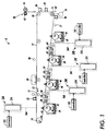
- FIG. 1 illustrates an electrophotographic printing machine 8 that is in accord with the principles of the present invention.
- the printing machine 8 is a single pass, Recharge-Expose-and-Develop, Image-on-Image (Read IOI) printer.
- the printing machine 8 includes an Active Matrix (AMAT) photoreceptor belt 10 which travels in the direction indicated by the arrow 12. Belt travel is brought about by mounting the photoreceptor belt about a driven roller 14 and tension rollers 16 and 18, and then driving the driven roller 14 with a motor 20.
- AMAT Active Matrix
- the image area is that part of the photoreceptor belt which is to receive the various actions and toner layers that produce the final composite color image. While the photoreceptor belt may have numerous image areas, since each image area is processed in the same way a description of the processing of one image area suffices to explain the operation of the printing machine 8.
- the imaging process begins with the image area passing a "precharge" erase lamp 21 that illuminates the image area so as to cause any residual charge which might exist on the image area to be discharged.
- a "precharge” erase lamp 21 that illuminates the image area so as to cause any residual charge which might exist on the image area to be discharged.
- Such erase lamps are common in high quality systems and their use for initial erasure is well known.
- a charging station comprised of a DC corotron 22.
- the DC corotron charges the image area in preparation for exposure to create a latent image for black toner.
- the DC corotron might charge the image area to a substantially uniform potential of about -500 volts. It should be understood that the actual charge placed on the photoreceptor will depend upon many variables, such as the black toner mass that is to be developed and the settings of the black development station (see below).
- the image area After passing the charging station the image area advances to an exposure station 24A.
- the charged image area is exposed to a modulated laser beam 26A from a raster output scanner 27A that raster scans the image area such that an electrostatic latent representation of a black image is produced.
- the modulation of the laser beam 26A is controlled such that the first scan line of the black latent image is imaged at a known position on the photoreceptor.
- the exposed image area with the black latent image passes a black development station 32 that advances black toner 34 onto the image area so as to develop a black toner image.
- the black development station 32 could be a magnetic brush developer, a scavengeless developer may be somewhat better.
- One benefit of scavengeless development is that it does not disturb previously deposited toner layers. Biasing is such as to effect discharged area development (DAD) of the lower (less negative) of the two voltage levels on the image area.
- DAD discharged area development
- the charged black toner 34 adheres to the exposed areas of the image area, thereby causing the voltage of the illuminated parts of the image area to be about -200 volts.
- the non-illuminated parts of the image area remain at about -500 volts.
- a recharging station 36 comprised of a DC corotron 38 and an AC scorotron 40.
- the recharging station 36 recharges the image area and its black toner layer using a technique known as split recharging.
- Split recharging is described in US-A-5,600,430. Briefly, the DC corotron 38 overcharges the image area to a voltage level greater than that desired when the image area is recharged, while the AC scorotron 40 reduces that voltage level to that which is desired.
- Split recharging serves to substantially eliminate voltage differences between toned areas and untoned areas and to reduce the level of residual charge remaining on the previously toned areas. This benefits subsequent development by different toners.
- the recharged image area with its black toner layer then advances to an exposure station 24B.
- a laser beam 26B from a raster output scanner 27B exposes the image area to produce an electrostatic latent representation of a yellow image.
- the operation of the exposure stations is described subsequently.
- the now re-exposed image area then advances to a yellow development station 46 that deposits yellow toner 48 onto the image area.
- a recharging station 50 where a DC scorotron 52 and an AC scorotron 54 split recharge the image area.
- An exposure station 24C then exposes the recharged image area.
- a modulated laser beam 26C from a raster output scanner 27C then exposes the image area to produce an electrostatic latent representation of a magenta image. Again, the operation of the exposure stations is described subsequently.
- magenta development station 56 that deposits magenta toner 58 onto the image area.
- image area advances another recharging station 60 where a DC corotron 62 and an AC scorotron 64 split recharge the image area.
- the recharged image area with its toner layers then advances to an exposure station 24D.
- a laser beam 26D from a raster output scanner 27D exposes the image area to produce an electrostatic latent representation of a cyan image.
- the re-exposed image area advances past a cyan development station 66 that deposits cyan toner 68 onto the image area.
- cyan toner 68 deposits cyan toner 68 onto the image area.
- four colors of toner are on the image area, resulting in a composite color image.
- the composite color toner image is comprised of individual toner particles that have charge potentials that vary widely. Directly transferring such a composite toner image onto a substrate would result in a degraded final image. Therefore it is beneficial to prepare the composite color toner image for transfer.
- a pretransfer erase lamp 72 discharges the image area to produce a relatively low charge level on the image area.
- the image area then passes a pretransfer DC scorotron 80 that performs a pre-transfer charging function.
- the image area continues to advance in the direction 12 past the driven roller 14.
- a substrate 82 is then placed over the image area using a sheet feeder (which is not shown).
- a detack corotron 86 that corotron neutralizes some of the charge on the substrate to assist separation of the substrate from the photoreceptor 10.
- the substrate is then directed into a fuser 90 where a heated fuser roller 92 and a pressure roller 94 create a nip through which the substrate 82 passes.
- the combination of pressure and heat at the nip causes the composite color toner image to fuse into the substrate.
- a chute guides the substrate to a catch tray, also not shown, for removal by an operator.
- the image area continues its travel and passes a preclean erase lamp 98. That lamp neutralizes most of the charge remaining on the photoreceptor belt. After passing the preclean erase lamp the residual toner and/or debris on the photoreceptor is removed at a cleaning station 99. The image area then passes once again to the precharge erase lamp 21 and the start of another printing cycle.
- the printer 8 also includes a system controller 101 that controls the overall operation of the printer.
- the system controller preferably comprises one or more programmable microprocessors that operate in accordance with a software program stored in a suitable memory.
- the system controller synchronizes the operation the printer 8 and provides video information that is used to modulate the laser beams 26A-26D.
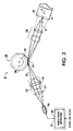
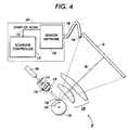
- FIGs 2, 3, and 4 present various views of a generic raster output scanner 27 as used in the printer 8.
- a video data network 103 within the controller 101 applied video data to a laser diode 106.
- the laser diode produces a laser beam 26 that is modulated according to the video data.
- the laser beam 26 is diverging.
- a spherical lens 114 collimates that diverging beam, which then enters a cylindrical lens 116, which focuses the beam in the slow scan (process) direction onto a polygon 120 having a plurality of mirrored facets 126.
- a piezoelectric actuator assembly 118 moves the cylindrical lens 116 in one plane in response to signals from a scanline controller circuit 119, which is also part of the controller 101. The operation of the scanline controller circuit is described subsequently.
- a motor 122 rotates the polygon 120 in a direction 124. This rotation causes the facets to sweep the laser beam in a scan plane.
- the sweeping laser beam passes through a post-scan optics system 128 that reconfigures the beam into a circular or elliptical cross-section and that refocuses that laser beam 26 onto the surface of the photoreceptor 10.
- the post-scan optics also corrects for various problems such as scan non-linearity (f-theta correction) and wobble (scanner motion or facet errors).
- the deflecting laser beam forms a scan line 129 on the photoreceptor 10.
- the position of the cylinder lens 116 influences the slow scan (process) direction location of the spot, and thus of the scan line, on the photoreceptor 10. If the cylinder lens is moved up or down the location of the scan line is moved in the slow scan direction an amount that depends on the system's magnification. For example, in one embodiment, if the cylinder lens moves 100 microns vertically, the scan line advances (in the direction 12) on the photoreceptor by 60 microns. Position signals applied to the piezoelectric actuator assembly 118 by the scanline controller circuit 119 cause the piezoelectric actuator assembly 118 to move the cylindrical lens 116, and thus the position of the scan line 129 (see Figure 3). The piezoelectric actuator assembly is described in more detail below. In the preferred embodiment, the position of the scan line is adjusted to compensate for photoreceptor position errors and for facet position errors.
- Photoreceptor position errors are determined using a plurality of evenly spaced timing marks 134 on the photoreceptor 10.
- a photosensor 137 senses those timing marks and applies timing signals to the scanline controller circuit 119.
- timing signals could be generated using a shaft encoder mounted on a photoreceptor roller.
- the scanline controller circuit 119 electronically determines when and how much the photoreceptor's position varies from ideal (since the photoreceptor should move at a constant rate, variations from that rate produce photoreceptor position variations). The scanline controller circuit 119 then determines and applies the correct position signal to the piezoelectric actuator assembly 118 such that the cylindrical lens 116 is moved the proper amount and in the proper direction to correctly position the scan line on the photoreceptor.
- scan line position errors that result from photoreceptor position variations are corrected using aerial control of the scan line position. This is particularly advantageous when printing in color since by correctly positioning the scan line produced by each of the raster output scanners 27A-27D a properly registered color image can result.
- Facet position errors are also compensated using aerial control of the scan line position.
- scan line misregistration can be a result of phasing errors. That is, the errors that result from a facet not being in the correct position to produce a scan line at the proper time.
- a particular scan line can be produced either earlier or later than ideal while the scan line position is adjusted on the photoreceptor by moving the cylindrical lens.
- each raster output scanner system includes a facet detector.
- the motor 122 might include an optical sensor that outputs a signal at certain times of its rotation.
- Another example might be a Hall sensor that tracks the rotation of the polygon 120.
- the printing machine 8 uses a start of scan sensor for facet position detection.
- Figure 4 best illustrates start-of-scan sensor detection.
- a receiving end 146 of an optical fiber 148 is strategically placed in the scan path of the laser beam 26.
- the collected light flux is guided to a sensor network 150, which is a part of the controller 101.
- the sensor network which includes a light sensitive element, senses the collected light flux and generates a start-of-scan signal (on a line 151).
- the start-of-scan signal that is applied via a line 151 to the scanline controller circuit 119 and to the video data network 103.
- the scanline controller circuit 119 determines the rotational velocity of the polygon.
- the video data network determines the proper time to apply video data to the laser diode 106.
- the scanline controller 119 knows the position of the photoreceptor and the start-of-scan rate the scanline controller can determine how far the position of the photoreceptor will be from ideal when the facet that is to produce the next scan line creates a start-of-scan signal. Then, by applying the correct position signal to the piezoelectric actuator assembly 118 the cylindrical lens 116 is moved the proper amount and in the proper direction to correctly position the scan line on the photoreceptor.
- piezoelectric actuator assemblies can be used for purposes other then for compensating for photoreceptor motion and facet position errors.
- piezoelectric actuator assemblies can also be used to maintain the scan line position at a fixed position despite polygon facet defects.
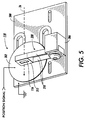
- FIG. 5 illustrates a generic piezoelectric actuator assembly 118 as used in the printer 8. That assembly includes a mounting frame 200, which is beneficially used to also mount a laser diode 106. However, that is not required and Figure 5 only shows the laser beam 26.
- a piezoelectric disk 202 having metal-plated surfaces is mounted on the mounting frame 200 such that the one of the metal-plated surfaces connects to the mounting frame.
- the mounting frame acts as an electrical ground for the piezoelectric disk (alternatively an electrical connection can be made to the piezoelectric disk using a wire).
- the other metal-plated surface receives via a wire the motion error signal. The position signal is applied across the piezoelectric disk so as to induce that disk to expand and contract.
- One beneficial piezoelectric disk is a high displacement actuator sold as "Rainbow” by Aura Ceramics.
- Other options include stacking various piezoelectric disks together.
- an arm mount 206 Also mounted to the mounting frame 200 is an arm mount 206. Attached to that mount is a flexible arm assembly 208. That assembly is comprised of two flexible arms 210 that are flexible in the direction that is normal to the surface of the mounting frame 200, but that are rigid in the direction that is parallel to the surface of the mounting frame. At the end of the flexible arm assembly is a lens holder 212 that holds the pre-polygon cylinder lens 116. The flexible arm assembly mounts to the arm mount 206 such that the flexible arms 210 are biased toward the piezoelectric disk 202. The rigidity of the flexible arms maintains the cylindrical lens at the proper focal position relative to the laser diode 30.
- the flexibility of the flexible arms enables the piezoelectric element to control the spot position in the slow scan (process) direction without rotating or otherwise perturbing the cylinder lens in an undesirable direction.
- Fundamental mechanical properties of dual flexure arms allow this motion while minimizing undesired motion of the cylinder lens, including rotation about and translation along the axis formed by the laser beam path or the axis which defines the cylinder lens curved surface.
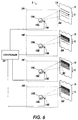
- the printer 8 incorporates aerial control of the scan line position. This is highly advantageous in a color printer since the registration of the individual latent images is simplified. Figure 6 illustrates such registration.
- raster output scanner 24A produces a first latent image on the photoreceptor 10.
- the controller 101 controls the piezoelectric actuator assembly 118B such that the second latent image is properly registered with the first latent image despite facet position errors and photoreceptor position errors.
- the controller 101 controls the other piezoelectric actuator assemblies such that proper registration is achieved.
Landscapes
- Engineering & Computer Science (AREA)
- Multimedia (AREA)
- Signal Processing (AREA)
- Mechanical Optical Scanning Systems (AREA)
- Exposure Or Original Feeding In Electrophotography (AREA)
- Color Electrophotography (AREA)
- Color, Gradation (AREA)
- Laser Beam Printer (AREA)
- Facsimile Scanning Arrangements (AREA)
Applications Claiming Priority (2)
| Application Number | Priority Date | Filing Date | Title |
|---|---|---|---|
| US09/210,188 US6141031A (en) | 1998-12-11 | 1998-12-11 | Aerial color registration |
| US210188 | 1998-12-11 |
Publications (3)
| Publication Number | Publication Date |
|---|---|
| EP1009157A2 true EP1009157A2 (fr) | 2000-06-14 |
| EP1009157A3 EP1009157A3 (fr) | 2001-05-02 |
| EP1009157B1 EP1009157B1 (fr) | 2013-06-12 |
Family
ID=22781920
Family Applications (1)
| Application Number | Title | Priority Date | Filing Date |
|---|---|---|---|
| EP99309779.9A Expired - Lifetime EP1009157B1 (fr) | 1998-12-11 | 1999-12-06 | Repérage de couleurs |
Country Status (3)
| Country | Link |
|---|---|
| US (1) | US6141031A (fr) |
| EP (1) | EP1009157B1 (fr) |
| JP (1) | JP2000168149A (fr) |
Cited By (1)
| Publication number | Priority date | Publication date | Assignee | Title |
|---|---|---|---|---|
| US7193640B2 (en) | 2003-10-31 | 2007-03-20 | Polaroid Corporation | Printer color registration correction |
Families Citing this family (8)
| Publication number | Priority date | Publication date | Assignee | Title |
|---|---|---|---|---|
| US6456309B1 (en) | 2000-07-26 | 2002-09-24 | Xerox Corporation | Color image registration based upon belt and raster output scanner synchronization |
| JP4904617B2 (ja) * | 2000-09-11 | 2012-03-28 | コニカミノルタホールディングス株式会社 | 画像形成装置 |
| US6940536B2 (en) * | 2002-11-07 | 2005-09-06 | Xerox Corporation | System architecture for scan line non-linearity compensation in a ROS system |
| US7965901B2 (en) * | 2003-10-31 | 2011-06-21 | Hewlett-Packard Development Company, L.P. | Hard imaging methods and devices and optical scanning systems |
| US7693197B2 (en) * | 2003-10-31 | 2010-04-06 | Hewlett-Packard Development Company, L.P. | Laser scanning apparatuses, laser scanning methods and article manufacture |
| US7061514B2 (en) * | 2004-01-30 | 2006-06-13 | Hewlett-Packard Development Company, L.P. | Scanning system |
| US7460146B2 (en) * | 2004-07-28 | 2008-12-02 | Towner David K | Dynamic correction of field curvature from a scanner |
| CN110381808B (zh) * | 2017-01-06 | 2022-03-15 | 飞通尼护理股份有限公司 | 自定向成像设备及使用方法 |
Family Cites Families (9)
| Publication number | Priority date | Publication date | Assignee | Title |
|---|---|---|---|---|
| GB1513176A (en) * | 1976-06-22 | 1978-06-07 | Decca Ltd | Lens mount |
| US4664487A (en) * | 1985-09-30 | 1987-05-12 | Rockwell International Corporation | Laser mirror positioning apparatus |
| JPS6390022A (ja) * | 1986-10-02 | 1988-04-20 | Matsushita Electric Ind Co Ltd | 回転ヘツド装置 |
| US5208796A (en) * | 1991-01-03 | 1993-05-04 | Xerox Corporation | Method and apparatus for transverse image registration on photoreceptive belts |
| JPH052142A (ja) * | 1991-06-24 | 1993-01-08 | Dainippon Screen Mfg Co Ltd | 光ビームの走査線偏位量検出方法および光ビーム走査装置 |
| US5287125A (en) * | 1991-08-05 | 1994-02-15 | Xerox Corporation | Raster output scanner with process direction spot position control |
| US5281812A (en) * | 1992-07-31 | 1994-01-25 | Eastman Kodak Company | Light beam scanning system including piezoelectric means for correction of cross scan error |
| US5877494A (en) * | 1996-07-29 | 1999-03-02 | Agfa Division, Bayer Corporation | Beam error correction using movable correction element |
| US5750986A (en) * | 1997-01-21 | 1998-05-12 | Xerox Corporation | Multiple laser beam differential intensity and start of scan sensing |
-
1998
- 1998-12-11 US US09/210,188 patent/US6141031A/en not_active Expired - Lifetime
-
1999
- 1999-11-16 JP JP11325516A patent/JP2000168149A/ja not_active Withdrawn
- 1999-12-06 EP EP99309779.9A patent/EP1009157B1/fr not_active Expired - Lifetime
Non-Patent Citations (1)
| Title |
|---|
| None |
Cited By (1)
| Publication number | Priority date | Publication date | Assignee | Title |
|---|---|---|---|---|
| US7193640B2 (en) | 2003-10-31 | 2007-03-20 | Polaroid Corporation | Printer color registration correction |
Also Published As
| Publication number | Publication date |
|---|---|
| US6141031A (en) | 2000-10-31 |
| EP1009157A3 (fr) | 2001-05-02 |
| JP2000168149A (ja) | 2000-06-20 |
| EP1009157B1 (fr) | 2013-06-12 |
Similar Documents
| Publication | Publication Date | Title |
|---|---|---|
| JP3295281B2 (ja) | レーザー走査光学装置 | |
| EP0121033B1 (fr) | Système de balayage avec laser à état solide et machine électrophotographique contenant un tel système | |
| EP0528555B1 (fr) | Correction à deux modes de la distorsion d'images dans un appareil d'impression xerographique | |
| US6232991B1 (en) | ROS bow compensation | |
| US6141031A (en) | Aerial color registration | |
| JPH08262352A (ja) | 光走査装置ならびにこの光走査装置を利用した画像形成装置 | |
| US6055005A (en) | Color printer with jitter signature matching | |
| US6355926B1 (en) | Raster output scanner beam steering | |
| EP0929187B1 (fr) | Imprimante avec concordance des facettes | |
| US6023286A (en) | Moving mirror motion quality compensation | |
| JPH04152365A (ja) | 画像形成装置 | |
| US20090135312A1 (en) | Apparatus For And Method Of Forming Images With Oscillation Mirror | |
| US6351277B1 (en) | Direct digital synthesis pixel clock generator | |
| US6144478A (en) | Flexible arm piezoelectric lens mover | |
| US6456309B1 (en) | Color image registration based upon belt and raster output scanner synchronization | |
| GB2355123A (en) | Colour laser printer using a plurality of lasers | |
| GB2416946A (en) | Dynamic correction of field curvature | |
| US6285389B1 (en) | Single sensor laser beam synchronizer and intensity regulator | |
| US5946111A (en) | Raster output scanner to photoreceptor mount | |
| US6278109B1 (en) | Facet tracking using wavelength variations and a dispersive element | |
| US7005631B2 (en) | Beam position adjusting method for optical scanning device | |
| EP1049319B1 (fr) | Commande de position du balayage auxilaire | |
| US6958471B2 (en) | Method and apparatus for forming image | |
| US5729278A (en) | Sidewinder raster output scanner | |
| JP2005241753A (ja) | 光走査装置及び画像形成装置 |
Legal Events
| Date | Code | Title | Description |
|---|---|---|---|
| PUAI | Public reference made under article 153(3) epc to a published international application that has entered the european phase |
Free format text: ORIGINAL CODE: 0009012 |
|
| AK | Designated contracting states |
Kind code of ref document: A2 Designated state(s): DE FR GB |
|
| AX | Request for extension of the european patent |
Free format text: AL;LT;LV;MK;RO;SI |
|
| PUAL | Search report despatched |
Free format text: ORIGINAL CODE: 0009013 |
|
| AK | Designated contracting states |
Kind code of ref document: A3 Designated state(s): AT BE CH CY DE DK ES FI FR GB GR IE IT LI LU MC NL PT SE |
|
| AX | Request for extension of the european patent |
Free format text: AL;LT;LV;MK;RO;SI |
|
| 17P | Request for examination filed |
Effective date: 20011102 |
|
| AKX | Designation fees paid |
Free format text: DE FR GB |
|
| 17Q | First examination report despatched |
Effective date: 20071213 |
|
| GRAP | Despatch of communication of intention to grant a patent |
Free format text: ORIGINAL CODE: EPIDOSNIGR1 |
|
| GRAS | Grant fee paid |
Free format text: ORIGINAL CODE: EPIDOSNIGR3 |
|
| GRAA | (expected) grant |
Free format text: ORIGINAL CODE: 0009210 |
|
| AK | Designated contracting states |
Kind code of ref document: B1 Designated state(s): DE FR GB |
|
| REG | Reference to a national code |
Ref country code: GB Ref legal event code: FG4D |
|
| REG | Reference to a national code |
Ref country code: DE Ref legal event code: R096 Ref document number: 69944777 Country of ref document: DE Effective date: 20130801 |
|
| PLBE | No opposition filed within time limit |
Free format text: ORIGINAL CODE: 0009261 |
|
| STAA | Information on the status of an ep patent application or granted ep patent |
Free format text: STATUS: NO OPPOSITION FILED WITHIN TIME LIMIT |
|
| 26N | No opposition filed |
Effective date: 20140313 |
|
| REG | Reference to a national code |
Ref country code: DE Ref legal event code: R097 Ref document number: 69944777 Country of ref document: DE Effective date: 20140313 |
|
| PGFP | Annual fee paid to national office [announced via postgrant information from national office to epo] |
Ref country code: DE Payment date: 20141121 Year of fee payment: 16 Ref country code: GB Payment date: 20141126 Year of fee payment: 16 |
|
| PGFP | Annual fee paid to national office [announced via postgrant information from national office to epo] |
Ref country code: FR Payment date: 20141217 Year of fee payment: 16 |
|
| REG | Reference to a national code |
Ref country code: DE Ref legal event code: R119 Ref document number: 69944777 Country of ref document: DE |
|
| GBPC | Gb: european patent ceased through non-payment of renewal fee |
Effective date: 20151206 |
|
| REG | Reference to a national code |
Ref country code: FR Ref legal event code: ST Effective date: 20160831 |
|
| PG25 | Lapsed in a contracting state [announced via postgrant information from national office to epo] |
Ref country code: DE Free format text: LAPSE BECAUSE OF NON-PAYMENT OF DUE FEES Effective date: 20160701 Ref country code: GB Free format text: LAPSE BECAUSE OF NON-PAYMENT OF DUE FEES Effective date: 20151206 |
|
| PG25 | Lapsed in a contracting state [announced via postgrant information from national office to epo] |
Ref country code: FR Free format text: LAPSE BECAUSE OF NON-PAYMENT OF DUE FEES Effective date: 20151231 |