EP1009231B1 - Strömungserzeugende fischleitanlage und ihre anwendungsverfahren - Google Patents
Strömungserzeugende fischleitanlage und ihre anwendungsverfahren Download PDFInfo
- Publication number
- EP1009231B1 EP1009231B1 EP98928881A EP98928881A EP1009231B1 EP 1009231 B1 EP1009231 B1 EP 1009231B1 EP 98928881 A EP98928881 A EP 98928881A EP 98928881 A EP98928881 A EP 98928881A EP 1009231 B1 EP1009231 B1 EP 1009231B1
- Authority
- EP
- European Patent Office
- Prior art keywords
- propeller
- current
- water
- fish
- velocity
- Prior art date
- Legal status (The legal status is an assumption and is not a legal conclusion. Google has not performed a legal analysis and makes no representation as to the accuracy of the status listed.)
- Expired - Lifetime
Links
- 241000251468 Actinopterygii Species 0.000 title claims abstract description 109
- 239000000411 inducer Substances 0.000 title claims description 75
- 238000000034 method Methods 0.000 title claims description 29
- XLYOFNOQVPJJNP-UHFFFAOYSA-N water Substances O XLYOFNOQVPJJNP-UHFFFAOYSA-N 0.000 claims description 81
- 238000011144 upstream manufacturing Methods 0.000 claims description 16
- 238000012546 transfer Methods 0.000 claims description 3
- 230000002596 correlated effect Effects 0.000 claims description 2
- 230000001276 controlling effect Effects 0.000 claims 1
- 235000019688 fish Nutrition 0.000 description 98
- 230000004888 barrier function Effects 0.000 description 10
- 241000894007 species Species 0.000 description 10
- 230000003068 static effect Effects 0.000 description 8
- 239000013598 vector Substances 0.000 description 7
- 230000008901 benefit Effects 0.000 description 6
- 239000010813 municipal solid waste Substances 0.000 description 5
- 230000003542 behavioural effect Effects 0.000 description 4
- 244000062645 predators Species 0.000 description 4
- 241000972773 Aulopiformes Species 0.000 description 3
- 241000196324 Embryophyta Species 0.000 description 3
- 238000012423 maintenance Methods 0.000 description 3
- 239000012528 membrane Substances 0.000 description 3
- 230000005012 migration Effects 0.000 description 3
- 238000013508 migration Methods 0.000 description 3
- 230000008569 process Effects 0.000 description 3
- 235000019515 salmon Nutrition 0.000 description 3
- 240000007320 Pinus strobus Species 0.000 description 2
- 241000242583 Scyphozoa Species 0.000 description 2
- 230000005684 electric field Effects 0.000 description 2
- 231100001261 hazardous Toxicity 0.000 description 2
- 238000009434 installation Methods 0.000 description 2
- 230000002262 irrigation Effects 0.000 description 2
- 238000003973 irrigation Methods 0.000 description 2
- 230000005541 medical transmission Effects 0.000 description 2
- 239000011295 pitch Substances 0.000 description 2
- 239000013535 sea water Substances 0.000 description 2
- 239000011800 void material Substances 0.000 description 2
- 241000555828 Eurypharyngidae Species 0.000 description 1
- 241000277263 Salmo Species 0.000 description 1
- 229910000831 Steel Inorganic materials 0.000 description 1
- 230000008859 change Effects 0.000 description 1
- 238000006243 chemical reaction Methods 0.000 description 1
- 238000010276 construction Methods 0.000 description 1
- 230000007423 decrease Effects 0.000 description 1
- 230000003247 decreasing effect Effects 0.000 description 1
- 230000003111 delayed effect Effects 0.000 description 1
- 230000001419 dependent effect Effects 0.000 description 1
- 238000013461 design Methods 0.000 description 1
- 238000007599 discharging Methods 0.000 description 1
- 235000013305 food Nutrition 0.000 description 1
- 229920002681 hypalon Polymers 0.000 description 1
- 230000003116 impacting effect Effects 0.000 description 1
- 230000006872 improvement Effects 0.000 description 1
- 231100000518 lethal Toxicity 0.000 description 1
- 230000001665 lethal effect Effects 0.000 description 1
- 230000007774 longterm Effects 0.000 description 1
- 238000004519 manufacturing process Methods 0.000 description 1
- 239000000463 material Substances 0.000 description 1
- 238000012986 modification Methods 0.000 description 1
- 230000004048 modification Effects 0.000 description 1
- 210000003739 neck Anatomy 0.000 description 1
- 238000005086 pumping Methods 0.000 description 1
- 230000009467 reduction Effects 0.000 description 1
- 230000001932 seasonal effect Effects 0.000 description 1
- 239000010959 steel Substances 0.000 description 1
Images



Classifications
-
- E—FIXED CONSTRUCTIONS
- E02—HYDRAULIC ENGINEERING; FOUNDATIONS; SOIL SHIFTING
- E02B—HYDRAULIC ENGINEERING
- E02B1/00—Equipment or apparatus for, or methods of, general hydraulic engineering, e.g. protection of constructions against ice-strains
- E02B1/006—Arresting, diverting or chasing away fish in water-courses or water intake ducts, seas or lakes, e.g. fish barrages, deterrent devices ; Devices for cleaning fish barriers
-
- A—HUMAN NECESSITIES
- A01—AGRICULTURE; FORESTRY; ANIMAL HUSBANDRY; HUNTING; TRAPPING; FISHING
- A01K—ANIMAL HUSBANDRY; AVICULTURE; APICULTURE; PISCICULTURE; FISHING; REARING OR BREEDING ANIMALS, NOT OTHERWISE PROVIDED FOR; NEW BREEDS OF ANIMALS
- A01K61/00—Culture of aquatic animals
-
- A—HUMAN NECESSITIES
- A01—AGRICULTURE; FORESTRY; ANIMAL HUSBANDRY; HUNTING; TRAPPING; FISHING
- A01K—ANIMAL HUSBANDRY; AVICULTURE; APICULTURE; PISCICULTURE; FISHING; REARING OR BREEDING ANIMALS, NOT OTHERWISE PROVIDED FOR; NEW BREEDS OF ANIMALS
- A01K79/00—Methods or means of catching fish in bulk not provided for in groups A01K69/00 - A01K77/00, e.g. fish pumps; Detection of fish; Whale fishery
-
- E—FIXED CONSTRUCTIONS
- E02—HYDRAULIC ENGINEERING; FOUNDATIONS; SOIL SHIFTING
- E02B—HYDRAULIC ENGINEERING
- E02B8/00—Details of barrages or weirs ; Energy dissipating devices carried by lock or dry-dock gates
- E02B8/08—Fish passes or other means providing for migration of fish; Passages for rafts or boats
- E02B8/085—Devices allowing fish migration, e.g. fish traps
-
- Y—GENERAL TAGGING OF NEW TECHNOLOGICAL DEVELOPMENTS; GENERAL TAGGING OF CROSS-SECTIONAL TECHNOLOGIES SPANNING OVER SEVERAL SECTIONS OF THE IPC; TECHNICAL SUBJECTS COVERED BY FORMER USPC CROSS-REFERENCE ART COLLECTIONS [XRACs] AND DIGESTS
- Y02—TECHNOLOGIES OR APPLICATIONS FOR MITIGATION OR ADAPTATION AGAINST CLIMATE CHANGE
- Y02A—TECHNOLOGIES FOR ADAPTATION TO CLIMATE CHANGE
- Y02A40/00—Adaptation technologies in agriculture, forestry, livestock or agroalimentary production
- Y02A40/60—Ecological corridors or buffer zones
-
- Y—GENERAL TAGGING OF NEW TECHNOLOGICAL DEVELOPMENTS; GENERAL TAGGING OF CROSS-SECTIONAL TECHNOLOGIES SPANNING OVER SEVERAL SECTIONS OF THE IPC; TECHNICAL SUBJECTS COVERED BY FORMER USPC CROSS-REFERENCE ART COLLECTIONS [XRACs] AND DIGESTS
- Y02—TECHNOLOGIES OR APPLICATIONS FOR MITIGATION OR ADAPTATION AGAINST CLIMATE CHANGE
- Y02A—TECHNOLOGIES FOR ADAPTATION TO CLIMATE CHANGE
- Y02A40/00—Adaptation technologies in agriculture, forestry, livestock or agroalimentary production
- Y02A40/80—Adaptation technologies in agriculture, forestry, livestock or agroalimentary production in fisheries management
- Y02A40/81—Aquaculture, e.g. of fish
Definitions
- This invention relates to a method and apparatus for modifying the behavior of fish. Specifically, it relates to a method and apparatus that modifies fish travel patterns by mechanically generating a current which creates a velocity head differential that fish can sense to guide them during their migration.
- Fish passage facilities constructed to allow fish to navigate around hazards or obstacles, can be broken down into two general categories, those for upstream passage and those for downstream fish passage.
- Upstream fish passage facilities typically incorporate some type of a structure to enable fish to swim up steep inclines.
- Traditional upstream fishways use a static head differential at the entrance of the fishway to create a current, attracting fish to the fishway.
- the static head differential is created by pumping water into a basin, where it then spills over a weir or through an orifice or slot. This generates a current field of limited influence, delaying the time fish are searching for the entrance.
- Downstream fish passage systems consist of a barrier to keep fish out of the plant intake, and a physical structure to route them around the plant.
- Various physical devices and systems have been developed to prohibit fish entrance to or guide fish away from these potentially hazardous areas. These devices can be broken down into behavioral deterrents and physical barriers.
- Physical barriers work by limiting the opening size of the intake such that a certain fish species or life stage of fish can not enter. This includes barriers such as closely spaced bar racks, traveling screens, and fixed screens.
- the disadvantages of these structures are that they are difficult and expensive to construct and maintain. They can also limit the water flow into the intake, thereby limiting power production or quantity of water available. These structures can also result in impingement of fish on the intake.
- Behavioral deterrents rely on fish behavior to divert fish from an intake. These deterrents include lights, electric fields, velocity/turbulence, and sound deterrents.
- Underwater lights including strobes
- Underwater lights are species-specific, and the visibility of lights, and therefore their effectiveness, is reduced in turbid water.
- Velocity/turbulence deterrents such as air bubble curtains and waterjets, are energy intensive and don't affect some species. It is difficult to establish an uninterrupted barrier and guide with underwater sound deterrents, and long term reliability is questionable with the present generation of sound generators. Also, the frequency and amplitude of the sound wave must be tuned for each individual species, and even life stage, of fish.
- Bypass structures work by releasing a certain amount of water. This discharge gives the fish water to swim in, and also creates an attraction current upstream of the bypass entrance. By discharging the water in front of the bypass, a void is created that the surrounding water fills. This movement of water toward the void creates the attraction current. This is known as a negative static head differential.
- One problem associated with these bypasses is that the field of attraction current is limited unless a large quantity of water is bypassed, which results in lost revenue.
- JP5263408A discloses a jellyfish removing device in a seawater intake.
- a wedge-shaped cover is mounted in the open end on the ocean side of a seawater intake and rudder-shaped plates are arranged on the outside of both side wall faces of the cover to form water channels.
- Propellers are mounted in the water channels and streams of water created by the propellers collide with the cover to remove jellyfish adhering to the cover 6.
- US-A-5 632 572 discloses a guidance apparatus and method for anadromous fish.
- Fish are guided in or by elongate faster moving channels defined in a body of slower moving water.
- Ring-like support frames are supported by floats and anchors in a water body at spaced distances along a faster moving channel to be defined.
- Each support frame carries one or more nozzles that receive pressurized water from a water supply system and disperse that water toward the next spacedly adjacent downstream support frame to define the faster moving channels without use of physical boundary members.
- the present invention provides a method of guiding fish through a body of water, the method comprising:
- the invention also provides an apparatus for guiding fish through a body of water, the apparatus comprising:
- the invention can be used to provide fish guidance systems which comprise commercially available components, which are adjustable for different site conditions, which are reasonably portable and deployable, which are easily maintainable, which will reduce water used for fish passage, which will facilitate routine plant operations, which keep fish in their river environment to reduce disease transmission and boost public relations, which eliminate physical handling of fish, and do not require a static head differential.
- the present invention is typically used in conjunction with a hydroelectric site that includes a dam and a turbine. It is desired to divert fish from the intake portion of the dam site so that they are not endangered by the turbine operation.
- a typical embodiment of the current inducer system 1 includes a low speed, high thrust propeller 10 with an appropriate device 12 to power its rotation. To vary the thrust of the system, the pitch, diameter, and speed of rotation of the propeller 10 may be varied, along with the motor horsepower.
- the propeller may have guide vanes on its discharge.
- the motor or device 12 to power its rotation may be electric, hydraulic, or pneumatic powered. If it is not of sufficiently low speed, a gearbox may be incorporated in line with the motor to reduce the speed.
- the motor 12 and propeller 10 are mounted in a substantially rigid frame 14.
- This frame 14 is adequately rigid to transfer force from the propeller 10 to the water.
- the frame 14 is adjustable to permit rotation and tilt of the propeller 10. It also supports a trashrack 24 on the suction side of the propeller 10 to prevent large debris from impacting the blades of the turbine.
- the frame 14 incorporates a platform 26 to provide access to the propeller 10 and motor 12 for operation and maintenance.
- Control of the current inducer may range from simple manual operation to complete automation depending on site characteristics.
- the main features to control include: on/off, speed control of the motor, the tilt, rotation, and depth of the propeller, and the number of units active. It is desirable to control these aspects of the current inducer to maintain a leading current to the bypass throughout changing river and turbine flow conditions. Therefore, the motor speed and propeller rotation may be correlated to the turbine control. For example, when the turbine shuts down, the output thrust of the current inducer may be reduced, the propeller may be redirected to face downstream, keeping the leading current aimed toward the bypass. Furthermore, when the turbine is on, the output thrust of the propeller 10 may be increased, and the propeller 10 may be redirected across or upstream. Additionally, the number of units active could be changed to match the turbine flow.
- Figure 8(a) illustrates a low turbine flow condition, wherein current vectors 19 due to turbine flow are low.
- the current vectors 18 due to the propellers 10 should be set relatively small and directed with a downstream component.
- the resultant current 20 flows toward the bypass 22.
- Figure 8(b) illustrates a high turbine flow condition.
- the current inducer in this case should be set such that the current vectors 18' resulting from the propellers 10 are higher and directed more across or upstream.
- the resultant current 20' also flows toward the bypass 22.
- the characteristics of the target species of fish to be influenced should be determined and considered. These characteristics include the depth at which the fish move in the water column, and the minimum velocity threshold of the fish. This establishes the height at which the current must be generated, and how strong the current must be to influence the fish.
- a velocity study of the area where the currents are to be modified is then performed.
- the current generated in the forebay due to turbine flow must be measured.
- Equipment is then selected based on the water velocity distribution curves and located such that a current greater than the fish's minimum velocity threshold can be generated toward the downstream bypass at all turbine flows. Due to the wide variety of commercially available equipment, this selection process is relatively easy.
- the location of the current inducer is also site dependent.
- the current inducer should be located upstream of the turbine intake such that the current vector 18 from the current inducer, when combined with the current vector 19 due to turbine flow, creates a current 20 leading to the bypass 22. Once this location is determined and the current inducers are installed, the actual current produced should be checked with a velocity study. This can be fine tuned by adjusting the direction and speed of the propeller 10 in the frame to change the angle and tilt of the current inducers.
- the site has a 27 ft. (8.2m) wide, 35 ft. (10.7m) deep trashrack and the turbines are capable of passing 2100 cfs (5.9 m 3 .s -1 ) There is an existing bypass approximately 35 ft. (10.7m) from the trashrack.
- the target species for downstream fish passage was Atlantic Salmon smolts, which typically travel within the top six feet (1.8m) of the water column.
- a surface current was created passing upstream of the intake and leading toward the bypass.
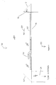
- two 2 horsepower (1.5kw) circulators were selected. This was based on manufacturer data showing each circulator generates an approximate flow of at least 2000 cfs (5.7m 3 s -1 ) at 65 feet (19.8m), which is the distance from the far side of the trashrack 16 to the bypass 22. See Figure 1. That arrangement creates a velocity well above the minimum velocity threshold that the salmon are capable of detecting, and would compete well with the deep turbine intake and its associated currents.
- the circulators have a propeller diameter of 3 feet (0.9m) and spin at 900 rpm (93.3 rad s -1 ).
- the propellers 10 were mounted in a steel frame 14 which was hung from a concrete retaining wall. This frame allows rotation and tilt of the propellers 10, and provided a platform 26 from which to hang a trashrack 24 upstream of the current inducers.
- the current inducers may be mounted directly on the trashrack 16 or mounted on floats and anchored to the river bottom, as long as the system is rigid enough to transfer a satisfactory current to the water.
- the current inducers work by developing a velocity head differential directly by the force of the propeller blades on the water. This is different from other typical fish passage systems that generate an attraction current by first creating a static head differential by pumps or other means, then allowing the water to flow, thereby creating a velocity head differential and a current.
- the direct conversion method used by the present invention is more efficient and allows more flexibility in the design of fish passage systems.
- the term current inducer is used because the propeller initially creates a high water velocity in a small area directly in front of the propeller. As this water passes by adjacent stationary water molecules, friction between the molecules induces a current into a larger area, while reducing the overall velocity of the water. This creates a relatively low velocity guiding current similar to the natural environment, rather than a high current that might be a deterrent to fish.
- louver is a widely accepted method of fish guidance. Louvers consist of an array of evenly spaced vertical slats aligned across a channel which lead to a bypass. The turbine flow passes through the slats, but the slats create hydraulic conditions which the fish detect and avoid. The fish move laterally away from the turbulence, and gradually downstream with the current into the bypass.
- the historic problem with louvers has been that the turbulence varies with turbine flow, and thus the system is not always running at peak efficiency.
- the trashrack bars 120 act as louver bars and a current inducer 110 is set at one end of the trashrack 116.
- a fine mesh trashrack 122 is positioned at the intake of the current inducer 110 and a fine mesh lead screen 124 is positioned leading to the bypass 126.
- the current inducer 110 is positioned to create a resultant current vector 128, which, when combined with the turbine flow 130, is perpendicular to the turbine intake. This forms turbulence 132 at the trashrack bars 120 and creates a flow lead across the trashrack 116 to the bypass 126. Fish reject this turbulence 132, which is consistent at all turbine flows.
- the lead screen 124 helps to direct the fish into the bypass 126.
- current inducers may be used in conjunction with fish screens.
- Fish screens are a fine mesh screen used to overlay the trashrack bars, thus decreasing the open area available for fish to enter the intake.
- the typical problem with fish screens arises when the intake velocity is high, and, because of the reduced intake area, fish are impinged on the screen. This problem is exacerbated when the screen is allowed to foul, further reducing the intake area and increasing the intake velocity at the nonfouled areas.
- the initial current field 222 ends upstream of the second current inducer 220 so as to overlap with the current field 224 of the second current inducer 220. This overlapping of the two induced current fields 222, 224 reduces the chance of fish passing between the influence of the two adjoining current inducers.
- FIG. 4 illustrates an application of the present invention in an upstream fishway 310.
- two current inducers 312, 314 are used, one on each side of the fishway entrance, to provide an attraction current 316 through angled bars 318 leading to the entrance.
- This enables the creation of a large, defined current field, with turbulence 320 created by the louver bars 318 directing the fish to the fishway entrance.
- This has a greater effectiveness as a current lead than typical upstream fishways that use a static head differential to generate an attraction current.
- surface collectors In some instances, such as in large reservoirs with surface current flow leading away from the dam area, surface collectors (or “gulpers”) are used to collect fish. These fish are then trucked around the dam. These surface collectors are massive, floating structures that provide attraction current by pumps mounted below the structure under screens. These pump down, and their suction pulls water over an entrance weir. The problem with these systems is that their current influence field is very small, so the structure must be positioned carefully to take advantage of natural surface currents. They are also expensive to construct.
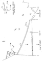
- Figures 5(a) and 5(b) illustrate an improvement over a conventional surface collector by utilizing current inducers to provide an attraction current to a collector.
- Figure 5(a) is an elevation view of a surface collector according to the present invention
- Figure 5(b) is a plan view of the surface collector.
- multiple current inducers 410, 412 are hung from a float 414.
- Lines 416 run from the float 414 to a rigid frame 418 which acts as the entrance to the collector.
- a net 420 is attached to the frame 418 and to floats 422 at the water surface.
- the base of the frame 418 is attached to a single mooring point.
- the net 420 necks down to a collection box 424 at the cod end.
- the current inducers 410, 412 When the current inducers 410, 412 are activated, they create a current field leading to the entrance of the net 420.
- the size of this field is limited by the current field of the motor and propeller, which is matched to the rope length between the current inducers and the net frame 418. This field size is much greater than that of conventional surface collectors.
- a more cost effective solution to this problem would be to mount several current inducers 512, 514 on a barge 510. See Figure 6. These current inducers 512, 514 would be placed to have a current field 516 width similar to that of the river. The barge 510 would proceed downstream at peak fish movement times with the current inducers 512, 514 operating, effectively herding the fish. This process could be repeated multiple times depending on its efficiency.
- An alternative solution to this problem is to mount multiple current inducers in series directly in the river. They would be installed such that their current influence fields overlap similar to that shown in Fig. 5. Current inducer installation would only be necessary in low current areas, and would not incur the massive civil works expenses associated with a pipeline the length of the river. Either of these options would be considerably less expensive than some of the present alternatives.
- An additional application of the current inducer improves fish bypass reducing predation.
- fish migrating downstream are successfully diverted around the turbine intakes at hydroelectric sites and into the fish bypass.
- the fish are discharged from the bypass into a low current plunge pool. Due to the high availability of food, predators position themselves in these pools and feed on the species being bypassed.
- a common solution to reduce fish mortality is to position the outfall in the turbine tailrace, such that the current created by the turbine will make it difficult for the predator to remain near the outfall site.
- the current will also provide a lead to guide the fish being bypassed away from the outfall site.
- the problem with this system is that the turbine discharge does not always provide a constant current, and many times it is not convenient to run the outfall into the tailrace.
- Figure 9 shows a fish bypass 610 which leads from a headpond 622 through a dam 612 into a plunge pool 614.
- a current inducer 616 is employed to generate a current 618 in the plunge pool leading away from the outfall 620.
- This current inducer generates a constant current at all turbine flows.
- the current inducer also allows the placement of the bypass in any location with a suitable depth plunge pool.
- FIG. 10 An alternative solution to the problems experienced when trying to create a continuous current across long intakes is shown in Figure 10.
- a floating barrier 710 is deployed to carry the surface current 712 to the bypass 714.
- the floating barrier 710 stretches from a point downstream of the current inducers 716 to the downstream edge of the bypass entrance 714.
- the barrier 710 consists of a float 720 on the water surface 722 which is attached to an impermeable or partially permeable membrane 724 extending into the water column, both of which stretch across the intake.
- the membrane 724 may be 3 (0.9m) to 4 (1.2m) feet deep, depending on the biological characteristics and the depth at which the target species to be bypassed typically travels.
- These floating barriers 710 may be made from any impermeable or partially permeable material with a high tensile strength, such as Hypalon. They are also available complete as an oil boom.
Landscapes
- Life Sciences & Earth Sciences (AREA)
- Environmental Sciences (AREA)
- Engineering & Computer Science (AREA)
- General Engineering & Computer Science (AREA)
- Marine Sciences & Fisheries (AREA)
- Animal Husbandry (AREA)
- Biodiversity & Conservation Biology (AREA)
- Civil Engineering (AREA)
- Mechanical Engineering (AREA)
- Structural Engineering (AREA)
- Zoology (AREA)
- Other Liquid Machine Or Engine Such As Wave Power Use (AREA)
- Farming Of Fish And Shellfish (AREA)
- Artificial Fish Reefs (AREA)
- Saccharide Compounds (AREA)
- Agricultural Chemicals And Associated Chemicals (AREA)
- Preparation Of Compounds By Using Micro-Organisms (AREA)
Claims (25)
- Verfahren zum Leiten von Fischen durch eine Wassermasse, wobei das Verfahren aufweist:Bereitstellen eines Strömungserzeugers (10) in der Wassermasse; undVerwenden des Strömungserzeugers (10), um mechanisch eine Strömung zu erzeugen, die Fische wahrnehmen können, um sie zu leiten, wobei die Strömung bezüglich der Wassermasse ohne Leitungen definiert ist, die sie von der Wassermasse unterscheidet;gekennzeichnet durch:Drehen eines Propellers (10) als Strömungserzeuger, um anfänglich in einem kleinen Bereich direkt vor dem Propeller (10) eine hohe Wassergeschwindigkeit zu erzeugen, wobei die Wassergeschwindigkeit dann in einem größeren Bereich eine Strömung mit einer insgesamt reduzierten Geschwindigkeit bewirkt.
- Verfahren nach Anspruch 1, das ferner das niedertourige Betreiben des Propellers (10) mit hoher Schubkraft aufweist.
- Verfahren nach Anspruch 1 oder 2, das ferner das Verwenden des Propellers (10) in Verbindung mit einem Fischsieb und das Erzeugen einer Strömung parallel zum Fischsieb aufweist, um die Fische vom Sieb abzustoßen.
- Verfahren nach einem der vorhergehenden Ansprüche, wobei die erzeugte Strömung einem Wassereinlauf benachbart ist und das ferner das Steuern der Drehzahl des Propellers (10) beruhend auf dem Durchfluß des Wassereinlaufs aufweist.
- Verfahren nach einem der vorhergehenden Ansprüche, das ferner die Ablenkung der Fische vom Einlaufabschnitt eines Wasserkraftwerks aufweist, das einen Damm und eine Turbine aufweist, so daß sie nicht durch den Turbinenbetrieb gefährdet werden.
- Verfahren nach einem der vorhergehenden Ansprüche, wobei der Propeller (10) gesteuert wird, um eine Hauptströmung zu einer Umgehung aufrechtzuerhalten, wobei überall die Fluß- und Turbinenströmungsbedingungen geändert werden.
- Verfahren nach Anspruch 5, wobei die Drehzahl der Propellerrotation mit der Steuerung der Turbine korreliert ist.
- Verfahren nach einem der vorhergehenden Ansprüche, das ferner das Einstellen der Richtung und Drehzahl des Propellers (10) aufweist.
- Verfahren nach einem der vorhergehenden Ansprüche, das ferner das aufeinanderfolgende Bereitstellen mehrerer Propeller (220) längs des Wasserstrahls aufweist.
- Verfahren nach einem der vorhergehenden Ansprüche, das ferner das Schützen des Propellers (10) durch Anbringen eines Einlaufrechens (24) auf der Saugseite des Propellers aufweist.
- Verfahren nach einem der vorhergehenden Ansprüche, das ferner das Erzeugen einer Strömung benachbart zu einem Sieb oder Einlaufrechen (116) und das Erzeugen einer Turbulenz an der Oberfläche des Siebs oder Einlaufrechens (116) aufweist, wenn die Strömung das Sieb oder den Einlaufrechen (116) passiert.
- Verfahren nach einem der vorhergehenden Ansprüche, das ferner das Anbringen des Propellers (10) und eines Motors (12), um den Propeller anzutreiben, in einem Rahmen (14) aufweist, der ausreichend starr ist, um Kraft vom Propeller (10) auf das Wasser zu übetragen.
- Verfahren nach Anspruch 12, das ferner das Einstellen der Rotationsachse des Propellers (10) in einer vertikalen Ebene aufweist.
- Verfahren nach Anspruch 12 oder 13, das ferner das Einstellen der Rotationsachse des Propellers in einer horizontalen Ebene aufweist.
- Verfahren nach Anspruch 1, das ferner das Treiben von Fischen durch Bereiche mit niedriger Geschwindigkeit in der Wassermasse aufweist.
- Verfahren nach Anspruch 15, das ferner das Anbringen des Propellers (512, 514) an einer Barkasse zu Treiben von Fischen durch Bereiche mit niedriger Geschwindigkeit in der Wassermasse aufweist.
- Vorrichtung zum Leiten von Fischen durch eine Wassermasse, wobei die Vorrichtung aufweist:einen Strömungserzeuger (10), der durch einen Rahmen (14) in der Wassermasse angebracht ist, und eingerichtet ist, mechanisch eine Strömung zu erzeugen, die Fische wahrnehmen können, um sie zu leiten, die bezüglich der Wassermasse ohne Leitungen definiert ist, die sie von der Wassermasse unterscheidet; dadurch gekennzeichnet, daß:der Strömungserzeuger (10) einen Propeller (10) und eine Vorrichtung (12) aufweist, die angeordnet ist, um den Propeller (10) zu drehen, um anfänglich in einem kleinen Bereich direkt vor dem Propeller (10) eine hohe Wassergeschwindigkeit zu erzeugen, wobei die hohe Wassergeschwindigkeit dann in einem größeren Bereich eine Strömung mit einer insgesamt reduzierten Geschwindigkeit bewirkt.
- Vorrichtung nach Anspruch 17, wobei der Rahmen (14) ein im wesentlichen starrer Rahmen ist, der eine Tiefeneinstellung des Propellers (10) zuläßt und daß die Vorrichtung (12) den Propeller (10) dreht.
- Vorrichtung nach Anspruch 17 oder 18, wobei der Rahmen (14) ein im wesentlichen starrer Rahmen ist, der eine Neigung in einer vertikalen Ebene und eine Rotation in einer horizontalen Ebene des Propellers (10) zuläßt und daß die Vorrichtung (12) den Propeller (10) dreht.
- Vorrichtung nach einem der Ansprüche 17 bis 19, wobei mehrere Propeller (220) aufeinanderfolgend längs des Wasserstrahls vorgesehen sind.
- Vorrichtung nach einem der Ansprüche 17 bis 19, wobei der Propeller (110) senkrecht zu einem Einlaufrechen (116) angebracht ist, um den Einlaufrechen als ein Leitgitter zu nutzen.
- Vorrichtung nach einem der Ansprüche 17 bis 21, wobei der Propeller (10) ein niedertouriger Propeller mit hoher Schubkraft ist.
- Vorrichtung nach einem der Ansprüche 17 bis 22, wobei die Vorrichtung (12), um den Propeller (10) zu drehen, ein Elektro-, Hydraulik- oder Druckluftmotor ist.
- Vorrichtung nach Anspruch 17, die ferner einen zweiten Rahmen (418), ein Netz (420), das durch den zweiten Rahmen gehalten wird, und einen Sammelkasten (424) aufweist, der an einem verengten Ende des Netzes angeordnet ist; wobei der Propeller (10) so angeordnet ist, daß er einen Wasserstrahl in die Wassermasse schleudert, so daß der geschleuderte Strahl zum Sammelkasten (424) gerichtet in das Netz (420) geht.
- Vorrichtung nach Anspruch 17, die ferner ein Paar Sätze von Leitgitterstäben (318) aufweist, die an einem Eingang zu einem Fischgangkanal angeordnet sind und von dort auseinanderlaufen, wobei der Strömungserzeuger (10) auf einer Stromaufwärtsseite jedes der Sätze von Leitgitterstäben (318) angeordnet ist, um eine Turbulenz auf einer Stromaufwärtsseite jedes der Sätze von Leitgitterstäben zu erzeugen.
Applications Claiming Priority (3)
| Application Number | Priority Date | Filing Date | Title |
|---|---|---|---|
| US4931597P | 1997-06-10 | 1997-06-10 | |
| US49315P | 1997-06-10 | ||
| PCT/US1998/011488 WO1998056241A2 (en) | 1997-06-10 | 1998-06-09 | Flow inducer fish guide and method of using same |
Publications (3)
| Publication Number | Publication Date |
|---|---|
| EP1009231A1 EP1009231A1 (de) | 2000-06-21 |
| EP1009231A4 EP1009231A4 (de) | 2000-09-20 |
| EP1009231B1 true EP1009231B1 (de) | 2006-01-25 |
Family
ID=21959168
Family Applications (1)
| Application Number | Title | Priority Date | Filing Date |
|---|---|---|---|
| EP98928881A Expired - Lifetime EP1009231B1 (de) | 1997-06-10 | 1998-06-09 | Strömungserzeugende fischleitanlage und ihre anwendungsverfahren |
Country Status (10)
| Country | Link |
|---|---|
| US (1) | US6102619A (de) |
| EP (1) | EP1009231B1 (de) |
| AT (1) | ATE316330T1 (de) |
| AU (1) | AU745283B2 (de) |
| CA (1) | CA2293267C (de) |
| DE (1) | DE69833323D1 (de) |
| IS (1) | IS5290A (de) |
| NO (1) | NO996087L (de) |
| NZ (1) | NZ502147A (de) |
| WO (1) | WO1998056241A2 (de) |
Cited By (2)
| Publication number | Priority date | Publication date | Assignee | Title |
|---|---|---|---|---|
| RU2602446C2 (ru) * | 2015-09-03 | 2016-11-20 | Общество с ограниченной ответственностью "Осанна" (ООО "Осанна") | Комплексное рыбозащитное устройство |
| RU2619242C2 (ru) * | 2016-05-31 | 2017-05-12 | Общество с ограниченной ответственностью "Осанна" (ООО "Осанна") | Способ защиты рыб и других гидробионтов от попадания в водозаборное сооружение, способ защиты конструкций водозабора и рыбозащитного устройства от биологического обрастания, рыбозащитное устройство |
Families Citing this family (25)
| Publication number | Priority date | Publication date | Assignee | Title |
|---|---|---|---|---|
| US6038494A (en) * | 1997-05-21 | 2000-03-14 | Voith Hydro, Inc. | Control system for enhancing fish survivability in a hydroelectric power generation installation |
| US6712555B1 (en) * | 1998-07-20 | 2004-03-30 | Current Solutions, L.L.C. | Flow inducer fish guide and method of using same |
| WO2000056986A1 (en) * | 1999-03-18 | 2000-09-28 | Balaton Power Corporation S.A. | Fish protective water extraction method and apparatus |
| US6457436B1 (en) * | 1999-10-23 | 2002-10-01 | Jonathan P. Truebe | Paddlewheel fish deterrent and guide |
| US6467997B2 (en) | 2001-01-29 | 2002-10-22 | Battelle Memorial Institute | System and method for diverting fish around a structure |
| US6588370B1 (en) * | 2001-10-03 | 2003-07-08 | The United States Of America As Represented By The Secretary Of The Interior | Labyrinth weir and pool fishway |
| US6729800B2 (en) | 2001-10-12 | 2004-05-04 | Burns, Ii Gordon Charles | Flow velocity enhancement system |
| US6793440B2 (en) | 2002-01-15 | 2004-09-21 | The United States Of America As Represented By The Secretary Of The Army | Natural cue surface bypass collector |
| KR100448095B1 (ko) * | 2002-06-03 | 2004-09-13 | 하종근 | 취수구 해양생물 제거장치 |
| US6739802B2 (en) * | 2002-07-11 | 2004-05-25 | Bga Limited Partnership | Fish test circuit and method for evaluation of waterway barrier fish bypass systems |
| US6715959B2 (en) * | 2002-07-24 | 2004-04-06 | Bga Limited Partnership | Fish ladder for passing dams |
| US6726404B2 (en) | 2002-08-20 | 2004-04-27 | The United States Of America As Represented By The Secretary Of The Army | Device and method for simulating natural cues so that waterborne fauna avoid contacting manmade barriers |
| WO2006034436A2 (en) | 2004-09-21 | 2006-03-30 | Stout Medical Group, L.P. | Expandable support device and method of use |
| US7887258B2 (en) * | 2006-03-28 | 2011-02-15 | Mark Rubbert | Intake apparatus for dams |
| JP5542273B2 (ja) | 2006-05-01 | 2014-07-09 | スタウト メディカル グループ,エル.ピー. | 拡張可能な支持装置および使用方法 |
| US20100211176A1 (en) | 2008-11-12 | 2010-08-19 | Stout Medical Group, L.P. | Fixation device and method |
| WO2010056895A1 (en) | 2008-11-12 | 2010-05-20 | Stout Medical Group, L.P. | Fixation device and method |
| US8282836B2 (en) * | 2009-02-17 | 2012-10-09 | C-Water Technologies, Inc. | Water intake structure |
| US20110146802A1 (en) * | 2009-02-17 | 2011-06-23 | C-Water Technologies, Inc. | Water intake structure |
| US20120315092A1 (en) * | 2011-06-09 | 2012-12-13 | Quaglino Jr Angelo Vincent | Tidewater control system |
| US20130085535A1 (en) * | 2011-09-21 | 2013-04-04 | Flexmedex, LLC | Support device and method |
| JP2018078814A (ja) * | 2016-11-15 | 2018-05-24 | 富士ゼロックス株式会社 | 水中移動体及びプログラム |
| US10213815B1 (en) * | 2017-11-01 | 2019-02-26 | Benton Frederick Baugh | Method of cleaning the inlet to a thruster while in operation |
| NO345486B1 (no) * | 2019-05-13 | 2021-03-01 | Stranda Prolog As | Anordning og fremgangsmåte for flytting av marine organismer |
| CN113279363B (zh) * | 2021-05-27 | 2022-06-07 | 中国长江三峡集团有限公司 | 一种鱼类洄游智能调控装置及其运行方法 |
Family Cites Families (16)
| Publication number | Priority date | Publication date | Assignee | Title |
|---|---|---|---|---|
| US1722596A (en) * | 1929-01-21 | 1929-07-30 | Albert C Ross | Fishway |
| US2169249A (en) * | 1938-03-01 | 1939-08-15 | Harlan B Holmes | Method of and means for effecting downstream migration of fish about dams |
| US2761421A (en) * | 1946-12-31 | 1956-09-04 | Burkey Henry Theodore | Fish diverting method |
| US2751881A (en) * | 1946-12-31 | 1956-06-26 | Burkey Henry Theodore | Fish diverting means |
| US4029049A (en) * | 1976-04-29 | 1977-06-14 | Albert John Hillier | Fish barrier |
| US4260286A (en) * | 1979-04-19 | 1981-04-07 | Buchanan Robert R | Integrated fish migration system |
| NO166512C (no) * | 1981-02-04 | 1991-08-07 | Solbjoern Jacobsen | Fremgangsmaate til berging av fangsten fra en av et skip trukket traal. |
| US4437431A (en) * | 1981-11-06 | 1984-03-20 | Koch David L | Method and apparatus for diversion of downstream migrating anadromous fish |
| SU1355659A1 (ru) * | 1985-04-25 | 1987-11-30 | Волжский Научно-Исследовательский Институт Гидротехники И Мелиорации | Рыбозащитное устройство |
| RU2004680C1 (ru) * | 1990-09-21 | 1993-12-15 | Александр Евгеньевич Яковлев | Рыбоотвод рыбозащитного устройства |
| SU1781377A1 (ru) * | 1991-02-07 | 1992-12-15 | Novocherkassk Inzh Meliorat | Pыбoзaщиthoe уctpoйctbo boдoзaбophoгo coopужehия |
| US5263793A (en) * | 1991-11-19 | 1993-11-23 | Ormat Industries, Ltd. | Method of and apparatus for controlling turbulence in a wall-bounded fluid flow field |
| JPH05263408A (ja) * | 1992-03-17 | 1993-10-12 | Mitsubishi Heavy Ind Ltd | 海水取水口におけるクラゲ排除装置 |
| SE501257C2 (sv) * | 1993-05-26 | 1994-12-19 | Vattenfall Utveckling Ab | Anordning vid bropelare |
| AU5557494A (en) * | 1993-11-30 | 1995-06-19 | P.R.A. Manufacturing Ltd. | Fish lifting device |
| US5632572A (en) * | 1995-10-11 | 1997-05-27 | Chicha; George S. | Guidance apparatus and method for anadromous fish |
-
1998
- 1998-06-09 CA CA002293267A patent/CA2293267C/en not_active Expired - Fee Related
- 1998-06-09 DE DE69833323T patent/DE69833323D1/de not_active Expired - Lifetime
- 1998-06-09 WO PCT/US1998/011488 patent/WO1998056241A2/en not_active Ceased
- 1998-06-09 AT AT98928881T patent/ATE316330T1/de not_active IP Right Cessation
- 1998-06-09 US US09/101,900 patent/US6102619A/en not_active Expired - Fee Related
- 1998-06-09 AU AU80575/98A patent/AU745283B2/en not_active Ceased
- 1998-06-09 NZ NZ502147A patent/NZ502147A/en unknown
- 1998-06-09 EP EP98928881A patent/EP1009231B1/de not_active Expired - Lifetime
-
1999
- 1999-12-09 IS IS5290A patent/IS5290A/is unknown
- 1999-12-09 NO NO996087A patent/NO996087L/no not_active Application Discontinuation
Cited By (2)
| Publication number | Priority date | Publication date | Assignee | Title |
|---|---|---|---|---|
| RU2602446C2 (ru) * | 2015-09-03 | 2016-11-20 | Общество с ограниченной ответственностью "Осанна" (ООО "Осанна") | Комплексное рыбозащитное устройство |
| RU2619242C2 (ru) * | 2016-05-31 | 2017-05-12 | Общество с ограниченной ответственностью "Осанна" (ООО "Осанна") | Способ защиты рыб и других гидробионтов от попадания в водозаборное сооружение, способ защиты конструкций водозабора и рыбозащитного устройства от биологического обрастания, рыбозащитное устройство |
Also Published As
| Publication number | Publication date |
|---|---|
| ATE316330T1 (de) | 2006-02-15 |
| IS5290A (is) | 1999-12-09 |
| AU745283B2 (en) | 2002-03-21 |
| NO996087L (no) | 2000-02-10 |
| EP1009231A1 (de) | 2000-06-21 |
| US6102619A (en) | 2000-08-15 |
| DE69833323D1 (de) | 2006-04-13 |
| CA2293267A1 (en) | 1998-12-17 |
| NO996087D0 (no) | 1999-12-09 |
| CA2293267C (en) | 2007-05-01 |
| EP1009231A4 (de) | 2000-09-20 |
| WO1998056241A3 (en) | 1999-03-11 |
| AU8057598A (en) | 1998-12-30 |
| WO1998056241A2 (en) | 1998-12-17 |
| NZ502147A (en) | 2002-06-28 |
Similar Documents
| Publication | Publication Date | Title |
|---|---|---|
| EP1009231B1 (de) | Strömungserzeugende fischleitanlage und ihre anwendungsverfahren | |
| US6712555B1 (en) | Flow inducer fish guide and method of using same | |
| US5385428A (en) | Water intake fish diversion apparatus | |
| US6347908B1 (en) | Fish guidance system | |
| US6736572B2 (en) | Method and apparatus for reducing the pollution of boat harbors | |
| CN109312551B (zh) | 洄游鱼道装置 | |
| US6457436B1 (en) | Paddlewheel fish deterrent and guide | |
| EP2863735A1 (de) | Aquakulturbehälter und zirkulationsinduktionssystem | |
| KR102347116B1 (ko) | 해상풍력 발전 단지를 활용한 모듈식 생태통합 양식 시스템 | |
| US4481904A (en) | Fish conservation device | |
| US6729800B2 (en) | Flow velocity enhancement system | |
| US6467997B2 (en) | System and method for diverting fish around a structure | |
| JP2005131627A (ja) | 汚泥掻寄装置 | |
| Sheridan et al. | Screening at intakes and outfalls: measures to protect eel (Anguilla anguilla) | |
| US4040257A (en) | Wave-pump apparatus | |
| KR20090104205A (ko) | 해양구조물용 어도 | |
| KR20220115377A (ko) | 수상 부유쓰레기 수거장치 | |
| Chen et al. | Research progress on fish barrier measures | |
| JP4529103B2 (ja) | 浮遊渚を利用した水循環装置 | |
| JP4269310B2 (ja) | クラゲ流入防止装置 | |
| CN108661021A (zh) | 江海近岸入海口源头垃圾拦截及收集系列控制系统 | |
| RU2833541C1 (ru) | Способ снижения негативного влияния сборных теплых вод на электростанцию и водные биологические ресурсы | |
| RU2833541C9 (ru) | Способ снижения негативного влияния сбросных теплых вод на электростанцию и водные биологические ресурсы | |
| Taft III et al. | Angled screens and louvers for diverting fish at power plants | |
| RU156891U1 (ru) | Гидроструйное рыбонаправляющее устройство |
Legal Events
| Date | Code | Title | Description |
|---|---|---|---|
| PUAI | Public reference made under article 153(3) epc to a published international application that has entered the european phase |
Free format text: ORIGINAL CODE: 0009012 |
|
| 17P | Request for examination filed |
Effective date: 19991223 |
|
| AK | Designated contracting states |
Kind code of ref document: A1 Designated state(s): AT BE CH CY DE DK ES FI FR GB GR IE IT LI LU MC NL PT SE |
|
| AX | Request for extension of the european patent |
Free format text: LT PAYMENT 19991223;LV PAYMENT 19991223 |
|
| A4 | Supplementary search report drawn up and despatched |
Effective date: 20000804 |
|
| AK | Designated contracting states |
Kind code of ref document: A4 Designated state(s): AT BE CH CY DE DK ES FI FR GB GR IE IT LI LU MC NL PT SE |
|
| RIC1 | Information provided on ipc code assigned before grant |
Free format text: 7A 01K 79/00 A, 7A 01K 61/00 B, 7A 01K 73/02 B |
|
| 17Q | First examination report despatched |
Effective date: 20010726 |
|
| APBN | Date of receipt of notice of appeal recorded |
Free format text: ORIGINAL CODE: EPIDOSNNOA2E |
|
| APBR | Date of receipt of statement of grounds of appeal recorded |
Free format text: ORIGINAL CODE: EPIDOSNNOA3E |
|
| APBV | Interlocutory revision of appeal recorded |
Free format text: ORIGINAL CODE: EPIDOSNIRAPE |
|
| GRAP | Despatch of communication of intention to grant a patent |
Free format text: ORIGINAL CODE: EPIDOSNIGR1 |
|
| GRAS | Grant fee paid |
Free format text: ORIGINAL CODE: EPIDOSNIGR3 |
|
| GRAA | (expected) grant |
Free format text: ORIGINAL CODE: 0009210 |
|
| AK | Designated contracting states |
Kind code of ref document: B1 Designated state(s): AT BE CH CY DE DK ES FI FR GB GR IE IT LI LU MC NL PT SE |
|
| AX | Request for extension of the european patent |
Extension state: LT LV |
|
| PG25 | Lapsed in a contracting state [announced via postgrant information from national office to epo] |
Ref country code: NL Free format text: LAPSE BECAUSE OF FAILURE TO SUBMIT A TRANSLATION OF THE DESCRIPTION OR TO PAY THE FEE WITHIN THE PRESCRIBED TIME-LIMIT Effective date: 20060125 Ref country code: LI Free format text: LAPSE BECAUSE OF FAILURE TO SUBMIT A TRANSLATION OF THE DESCRIPTION OR TO PAY THE FEE WITHIN THE PRESCRIBED TIME-LIMIT Effective date: 20060125 Ref country code: IT Free format text: LAPSE BECAUSE OF FAILURE TO SUBMIT A TRANSLATION OF THE DESCRIPTION OR TO PAY THE FEE WITHIN THE PRESCRIBED TIME-LIMIT;WARNING: LAPSES OF ITALIAN PATENTS WITH EFFECTIVE DATE BEFORE 2007 MAY HAVE OCCURRED AT ANY TIME BEFORE 2007. THE CORRECT EFFECTIVE DATE MAY BE DIFFERENT FROM THE ONE RECORDED. Effective date: 20060125 Ref country code: FI Free format text: LAPSE BECAUSE OF FAILURE TO SUBMIT A TRANSLATION OF THE DESCRIPTION OR TO PAY THE FEE WITHIN THE PRESCRIBED TIME-LIMIT Effective date: 20060125 Ref country code: CH Free format text: LAPSE BECAUSE OF FAILURE TO SUBMIT A TRANSLATION OF THE DESCRIPTION OR TO PAY THE FEE WITHIN THE PRESCRIBED TIME-LIMIT Effective date: 20060125 Ref country code: BE Free format text: LAPSE BECAUSE OF FAILURE TO SUBMIT A TRANSLATION OF THE DESCRIPTION OR TO PAY THE FEE WITHIN THE PRESCRIBED TIME-LIMIT Effective date: 20060125 Ref country code: AT Free format text: LAPSE BECAUSE OF FAILURE TO SUBMIT A TRANSLATION OF THE DESCRIPTION OR TO PAY THE FEE WITHIN THE PRESCRIBED TIME-LIMIT Effective date: 20060125 |
|
| REG | Reference to a national code |
Ref country code: GB Ref legal event code: FG4D |
|
| REG | Reference to a national code |
Ref country code: CH Ref legal event code: EP |
|
| REG | Reference to a national code |
Ref country code: IE Ref legal event code: FG4D |
|
| REF | Corresponds to: |
Ref document number: 69833323 Country of ref document: DE Date of ref document: 20060413 Kind code of ref document: P |
|
| PG25 | Lapsed in a contracting state [announced via postgrant information from national office to epo] |
Ref country code: SE Free format text: LAPSE BECAUSE OF FAILURE TO SUBMIT A TRANSLATION OF THE DESCRIPTION OR TO PAY THE FEE WITHIN THE PRESCRIBED TIME-LIMIT Effective date: 20060425 Ref country code: DK Free format text: LAPSE BECAUSE OF FAILURE TO SUBMIT A TRANSLATION OF THE DESCRIPTION OR TO PAY THE FEE WITHIN THE PRESCRIBED TIME-LIMIT Effective date: 20060425 |
|
| PG25 | Lapsed in a contracting state [announced via postgrant information from national office to epo] |
Ref country code: DE Free format text: LAPSE BECAUSE OF FAILURE TO SUBMIT A TRANSLATION OF THE DESCRIPTION OR TO PAY THE FEE WITHIN THE PRESCRIBED TIME-LIMIT Effective date: 20060426 |
|
| PG25 | Lapsed in a contracting state [announced via postgrant information from national office to epo] |
Ref country code: ES Free format text: LAPSE BECAUSE OF FAILURE TO SUBMIT A TRANSLATION OF THE DESCRIPTION OR TO PAY THE FEE WITHIN THE PRESCRIBED TIME-LIMIT Effective date: 20060506 |
|
| PGFP | Annual fee paid to national office [announced via postgrant information from national office to epo] |
Ref country code: GB Payment date: 20060607 Year of fee payment: 9 |
|
| PGFP | Annual fee paid to national office [announced via postgrant information from national office to epo] |
Ref country code: IE Payment date: 20060616 Year of fee payment: 9 |
|
| PG25 | Lapsed in a contracting state [announced via postgrant information from national office to epo] |
Ref country code: PT Free format text: LAPSE BECAUSE OF FAILURE TO SUBMIT A TRANSLATION OF THE DESCRIPTION OR TO PAY THE FEE WITHIN THE PRESCRIBED TIME-LIMIT Effective date: 20060626 |
|
| LTIE | Lt: invalidation of european patent or patent extension |
Effective date: 20060125 |
|
| PG25 | Lapsed in a contracting state [announced via postgrant information from national office to epo] |
Ref country code: MC Free format text: LAPSE BECAUSE OF NON-PAYMENT OF DUE FEES Effective date: 20060630 |
|
| NLV1 | Nl: lapsed or annulled due to failure to fulfill the requirements of art. 29p and 29m of the patents act | ||
| REG | Reference to a national code |
Ref country code: CH Ref legal event code: PL |
|
| PLBE | No opposition filed within time limit |
Free format text: ORIGINAL CODE: 0009261 |
|
| STAA | Information on the status of an ep patent application or granted ep patent |
Free format text: STATUS: NO OPPOSITION FILED WITHIN TIME LIMIT |
|
| 26N | No opposition filed |
Effective date: 20061026 |
|
| GBPC | Gb: european patent ceased through non-payment of renewal fee |
Effective date: 20070609 |
|
| PG25 | Lapsed in a contracting state [announced via postgrant information from national office to epo] |
Ref country code: GR Free format text: LAPSE BECAUSE OF FAILURE TO SUBMIT A TRANSLATION OF THE DESCRIPTION OR TO PAY THE FEE WITHIN THE PRESCRIBED TIME-LIMIT Effective date: 20060426 Ref country code: FR Free format text: LAPSE BECAUSE OF FAILURE TO SUBMIT A TRANSLATION OF THE DESCRIPTION OR TO PAY THE FEE WITHIN THE PRESCRIBED TIME-LIMIT Effective date: 20070316 |
|
| PG25 | Lapsed in a contracting state [announced via postgrant information from national office to epo] |
Ref country code: IE Free format text: LAPSE BECAUSE OF NON-PAYMENT OF DUE FEES Effective date: 20070611 Ref country code: GB Free format text: LAPSE BECAUSE OF NON-PAYMENT OF DUE FEES Effective date: 20070609 |
|
| PG25 | Lapsed in a contracting state [announced via postgrant information from national office to epo] |
Ref country code: LU Free format text: LAPSE BECAUSE OF NON-PAYMENT OF DUE FEES Effective date: 20060609 |
|
| PG25 | Lapsed in a contracting state [announced via postgrant information from national office to epo] |
Ref country code: FR Free format text: LAPSE BECAUSE OF FAILURE TO SUBMIT A TRANSLATION OF THE DESCRIPTION OR TO PAY THE FEE WITHIN THE PRESCRIBED TIME-LIMIT Effective date: 20060125 Ref country code: CY Free format text: LAPSE BECAUSE OF FAILURE TO SUBMIT A TRANSLATION OF THE DESCRIPTION OR TO PAY THE FEE WITHIN THE PRESCRIBED TIME-LIMIT Effective date: 20060125 |