EP1009453B1 - Stufenweise einstellbare dosierungsspritze - Google Patents
Stufenweise einstellbare dosierungsspritze Download PDFInfo
- Publication number
- EP1009453B1 EP1009453B1 EP97935342A EP97935342A EP1009453B1 EP 1009453 B1 EP1009453 B1 EP 1009453B1 EP 97935342 A EP97935342 A EP 97935342A EP 97935342 A EP97935342 A EP 97935342A EP 1009453 B1 EP1009453 B1 EP 1009453B1
- Authority
- EP
- European Patent Office
- Prior art keywords
- plunger
- syringe
- ribs
- metering
- measuring ring
- Prior art date
- Legal status (The legal status is an assumption and is not a legal conclusion. Google has not performed a legal analysis and makes no representation as to the accuracy of the status listed.)
- Expired - Lifetime
Links
- 239000000463 material Substances 0.000 description 19
- 239000012530 fluid Substances 0.000 description 4
- 230000008901 benefit Effects 0.000 description 2
- 210000003811 finger Anatomy 0.000 description 2
- 210000003813 thumb Anatomy 0.000 description 2
- 230000003466 anti-cipated effect Effects 0.000 description 1
- POIUWJQBRNEFGX-XAMSXPGMSA-N cathelicidin Chemical compound C([C@@H](C(=O)N[C@@H](CCCNC(N)=N)C(=O)N[C@@H](CCCCN)C(=O)N[C@@H](CO)C(=O)N[C@@H](CCCCN)C(=O)N[C@@H](CCC(O)=O)C(=O)N[C@@H](CCCCN)C(=O)N[C@@H]([C@@H](C)CC)C(=O)NCC(=O)N[C@@H](CCCCN)C(=O)N[C@@H](CCC(O)=O)C(=O)N[C@@H](CC=1C=CC=CC=1)C(=O)N[C@@H](CCCCN)C(=O)N[C@@H](CCCNC(N)=N)C(=O)N[C@@H]([C@@H](C)CC)C(=O)N[C@@H](C(C)C)C(=O)N[C@@H](CCC(N)=O)C(=O)N[C@@H](CCCNC(N)=N)C(=O)N[C@@H]([C@@H](C)CC)C(=O)N[C@@H](CCCCN)C(=O)N[C@@H](CC(O)=O)C(=O)N[C@@H](CC=1C=CC=CC=1)C(=O)N[C@@H](CC(C)C)C(=O)N[C@@H](CCCNC(N)=N)C(=O)N[C@@H](CC(N)=O)C(=O)N[C@@H](CC(C)C)C(=O)N[C@@H](C(C)C)C(=O)N1[C@@H](CCC1)C(=O)N[C@@H](CCCNC(N)=N)C(=O)N[C@@H]([C@@H](C)O)C(=O)N[C@@H](CCC(O)=O)C(=O)N[C@@H](CO)C(O)=O)NC(=O)[C@H](CC=1C=CC=CC=1)NC(=O)[C@H](CC(O)=O)NC(=O)CNC(=O)[C@H](CC(C)C)NC(=O)[C@@H](N)CC(C)C)C1=CC=CC=C1 POIUWJQBRNEFGX-XAMSXPGMSA-N 0.000 description 1
- 238000006073 displacement reaction Methods 0.000 description 1
- 238000000034 method Methods 0.000 description 1
- 239000000825 pharmaceutical preparation Substances 0.000 description 1
- 238000007789 sealing Methods 0.000 description 1
Images


Classifications
-
- A—HUMAN NECESSITIES
- A61—MEDICAL OR VETERINARY SCIENCE; HYGIENE
- A61M—DEVICES FOR INTRODUCING MEDIA INTO, OR ONTO, THE BODY; DEVICES FOR TRANSDUCING BODY MEDIA OR FOR TAKING MEDIA FROM THE BODY; DEVICES FOR PRODUCING OR ENDING SLEEP OR STUPOR
- A61M5/00—Devices for bringing media into the body in a subcutaneous, intra-vascular or intramuscular way; Accessories therefor, e.g. filling or cleaning devices, arm-rests
- A61M5/178—Syringes
- A61M5/31—Details
- A61M5/315—Pistons; Piston-rods; Guiding, blocking or restricting the movement of the rod or piston; Appliances on the rod for facilitating dosing ; Dosing mechanisms
- A61M5/31533—Dosing mechanisms, i.e. setting a dose
- A61M5/31545—Setting modes for dosing
- A61M5/31548—Mechanically operated dose setting member
- A61M5/3155—Mechanically operated dose setting member by rotational movement of dose setting member, e.g. during setting or filling of a syringe
-
- A—HUMAN NECESSITIES
- A61—MEDICAL OR VETERINARY SCIENCE; HYGIENE
- A61M—DEVICES FOR INTRODUCING MEDIA INTO, OR ONTO, THE BODY; DEVICES FOR TRANSDUCING BODY MEDIA OR FOR TAKING MEDIA FROM THE BODY; DEVICES FOR PRODUCING OR ENDING SLEEP OR STUPOR
- A61M5/00—Devices for bringing media into the body in a subcutaneous, intra-vascular or intramuscular way; Accessories therefor, e.g. filling or cleaning devices, arm-rests
- A61M5/178—Syringes
- A61M5/31—Details
- A61M5/315—Pistons; Piston-rods; Guiding, blocking or restricting the movement of the rod or piston; Appliances on the rod for facilitating dosing ; Dosing mechanisms
- A61M5/31533—Dosing mechanisms, i.e. setting a dose
- A61M5/31545—Setting modes for dosing
- A61M5/31548—Mechanically operated dose setting member
- A61M5/3155—Mechanically operated dose setting member by rotational movement of dose setting member, e.g. during setting or filling of a syringe
- A61M5/31551—Mechanically operated dose setting member by rotational movement of dose setting member, e.g. during setting or filling of a syringe including axial movement of dose setting member
-
- A—HUMAN NECESSITIES
- A61—MEDICAL OR VETERINARY SCIENCE; HYGIENE
- A61M—DEVICES FOR INTRODUCING MEDIA INTO, OR ONTO, THE BODY; DEVICES FOR TRANSDUCING BODY MEDIA OR FOR TAKING MEDIA FROM THE BODY; DEVICES FOR PRODUCING OR ENDING SLEEP OR STUPOR
- A61M5/00—Devices for bringing media into the body in a subcutaneous, intra-vascular or intramuscular way; Accessories therefor, e.g. filling or cleaning devices, arm-rests
- A61M5/178—Syringes
- A61M5/31—Details
- A61M5/315—Pistons; Piston-rods; Guiding, blocking or restricting the movement of the rod or piston; Appliances on the rod for facilitating dosing ; Dosing mechanisms
- A61M5/31533—Dosing mechanisms, i.e. setting a dose
- A61M5/31545—Setting modes for dosing
- A61M5/31548—Mechanically operated dose setting member
- A61M5/31561—Mechanically operated dose setting member using freely adjustable volume steps
-
- A—HUMAN NECESSITIES
- A61—MEDICAL OR VETERINARY SCIENCE; HYGIENE
- A61M—DEVICES FOR INTRODUCING MEDIA INTO, OR ONTO, THE BODY; DEVICES FOR TRANSDUCING BODY MEDIA OR FOR TAKING MEDIA FROM THE BODY; DEVICES FOR PRODUCING OR ENDING SLEEP OR STUPOR
- A61M5/00—Devices for bringing media into the body in a subcutaneous, intra-vascular or intramuscular way; Accessories therefor, e.g. filling or cleaning devices, arm-rests
- A61M5/178—Syringes
- A61M5/31—Details
- A61M5/315—Pistons; Piston-rods; Guiding, blocking or restricting the movement of the rod or piston; Appliances on the rod for facilitating dosing ; Dosing mechanisms
- A61M5/31533—Dosing mechanisms, i.e. setting a dose
- A61M5/31545—Setting modes for dosing
- A61M5/31548—Mechanically operated dose setting member
- A61M5/31563—Mechanically operated dose setting member interacting with a displaceable stop member
-
- A—HUMAN NECESSITIES
- A61—MEDICAL OR VETERINARY SCIENCE; HYGIENE
- A61M—DEVICES FOR INTRODUCING MEDIA INTO, OR ONTO, THE BODY; DEVICES FOR TRANSDUCING BODY MEDIA OR FOR TAKING MEDIA FROM THE BODY; DEVICES FOR PRODUCING OR ENDING SLEEP OR STUPOR
- A61M5/00—Devices for bringing media into the body in a subcutaneous, intra-vascular or intramuscular way; Accessories therefor, e.g. filling or cleaning devices, arm-rests
- A61M5/178—Syringes
- A61M5/31—Details
- A61M5/315—Pistons; Piston-rods; Guiding, blocking or restricting the movement of the rod or piston; Appliances on the rod for facilitating dosing ; Dosing mechanisms
- A61M5/31565—Administration mechanisms, i.e. constructional features, modes of administering a dose
- A61M5/3159—Dose expelling manners
- A61M5/31591—Single dose, i.e. individually set dose administered only once from the same medicament reservoir, e.g. including single stroke limiting means
Definitions
- the present invention relates, generally, to apparatus and methods for delivering fluids. More particularly, the invention relates to a syringe having a plunger and barrel with a ring engaged on the plunger for limiting the motion of the plunger.
- the invention meters the amount of material dispensed from the barrel.
- the invention is optimally used to easily, repeatably and accurately deliver an incrementally adjustable dose of material. However, the invention also may have utility in other applications.
- the prior art syringe includes a cylinder, a plunger, and a measuring ring.
- the cylinder has a chamber, a cannula with a core at a first end, and an open second end.
- the cylinder also has exterior finger flanges disposed adjacent the open second end.
- the plunger has a piston head with a ring seal disposed in the cylinder for sealing the chamber at a first end of the plunger, a stem with four ribs in a cruciform shape fixedly connected to the piston head, and a thumb engaging flange fixedly connected to the four ribs at a second end of the plunger.
- Each of the ribs has an outer edge with a set of spaced notches.
- the notches of the ribs form an exterior thread.
- the measuring ring has an interior thread that is in mesh with the exterior thread. The ring measures and sets a selective dose volume of fluid in the chamber and bore.
- a problem with the prior art syringe is that it can be difficult to accurately set the measuring ring for a desired dose volume.
- a syringe latch invented by Ennis, III et al. and assigned to applicant's assignee is described in U.S. Patent No. 5,344,409.
- the disclosed syringe latch controls or meters the amount of material or fluid expelled from a syringe.
- the syringe has a syringe body having a chamber, a discharge end portion, and an opposite open end portion.
- a plunger is received in the syringe body.
- the measuring ring turns about the plunger on the meshing threads and includes latch means or detent areas for setting and holding the measuring ring to a rib at a predetermined position along the plunger. Two equally-spaced detent areas latch to one rib of the plunger every half turn of the measuring ring.
- the detent areas and thread pitch are calibrated so that each half turn of the syringe corresponds to a predetermined volume interval within the chamber. For example, if the syringe is designed so that each half turn of the measuring ring corresponds to a volume of 2 cubic centimeters (cc), then the syringe accurately meters dose volumes in 2 cc intervals, i.e.
- dose volume intervals of 2 cc, 4 cc, and 6 cc for example. Therefore, an operator can accurately adjust the dose volume merely by counting the number of times a detent area latches to a rib rather than using other indicia on the barrel. However, the operator is not able to easily and accurately meter doses that may fall between these 2cc intervals, for example 1 cc, 3 cc, and 5 cc doses, which do not correspond to a detent area on the measuring ring.
- Applicant's invention provides an adjustable dose device which overcome the limitations and shortcomings of the known art. Specifically, applicant's invention provides an improved syringe for easily, repeatably, and accurately metering doses of material. An operator measures a dose by counting the number of times the measuring ring latches to the plunger rather than visually aligning the measuring ring or using other indicia on the syringe. In addition, the parts of applicant's invention are easily substituted to create different dose intervals. Another advantage of the syringe is that, because the syringe is capable of metering out incremental doses, medicinal fluid or other material can be distributed within the syringe rather than in a separate vile.
- an adjustable dose syringe comprising:
- An operator sets a desired dose volume of material to be expelled from a syringe using the measuring ring and its detent area.
- the plunger and measuring ring may be substituted with others to obtain a different thread pitch, a different metering rib configuration, and/or a different detent area configuration, all of which can change the amount of material expelled as governed by each revolution or partial revolution of the measuring ring.
- a different thread pitch may result in a dose volume of 2 cc rather than 1 cc for each revolution of the measuring ring.
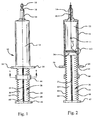
- Figures 1 and 2 illustrate an incrementally adjustable dose syringe (not in accordance with the invention) generally designated by reference numeral 10 which has an axis 11 and includes a hollow syringe body or cylinder 12 formed of a synthetic plastic material, or the like, and includes an elongated tubular cannula 14 having a tapered end portion 16 that is effectively closed by a removable cap 18.
- the cannula 14 has a bore 20 formed therein which communicates with an internal chamber 22 of the syringe body 12.
- the chamber 22 is adapted to receive a pharmaceutical preparation or other material which is intended to be dispensed from the chamber 22 through the bore 20 of the cannula 14.
- the chamber 22 has a uniform diameter from one end to the other and has an open end 24 opposite the cannula 14. Laterally extending handles or fmger flanges 26 are provided adjacent this end of the syringe body 12 in a conventional manner.
- the material is expelled from the chamber 22 through the bore 20 by a plunger 28 having a stem portion or an integral body formed ofa plurality of radially extending ribs, 29, 30, 32, 33.
- the plunger 28 has a first or inner end portion 32 which includes an integral or snap on seal piston 34 formed thereon and adapted to be inserted through an open end 24 of the syringe body 12.
- the opposite end of the plunger 28 has an integral palm or thumb engaging base or flange 42 formed thereon in a conventional manner.
- the seal piston 34 includes an integral annular seal or flange 36 surrounding the piston 34.
- the flange 36 has a diameter which is greater than the maximum diameter of the ribs 29, 30, 31, 33 of the plunger 28.
- the flange 36 is connected to the piston 34 by an integral annular web 38 which is formed in the piston 34 by an annular a V-shaped notch 40.
- the web 38 has a reduced thickness as compared to the flange 36 and is flexible to permit the flange 36 to serve as a wiping seal along the interior surface of the syringe body 12.
- a measuring ring or threaded nut 44 is provided on the plunger 28.
- the measuring ring 44 may be rotated to be properly located along the length of the plunger 28 to expel or meter a desired dose of material through the cannula 14.
- the measuring ring 44 generally has at least one detent area 78 and the plunger 28 generally has at least one metering rib 74 upon which the detent area 78 can be latched.
- An external thread is formed by notches in the metering rib or ribs 74 and any additional uniform ribs 76.
- the stroke of the plunger 28 and thus the volume of the expelled material is limited by adjusting the distance of the measuring ring 44 from the finger flanges 26.
- the measuring ring 44 can be repeatably set at incremental distances along the plunger 28 to dispense multiple doses from a single draw of material within the syringe.
- the ring 44 has an inner surface 46 which has a segmental rib or internal thread 48 that has an inner face 49.
- the thread 48 has as first detent area 50 and a second detent area 52, which are located 180 degrees apart.
- Each detent area is shown to have a first and second projection 54, 56 and 58, 60, each being made of a resilient conventional plastic material.
- Each projection extends from the inner circumference or inner face 49 in a radially inward direction.
- the device is shown with two detent areas 180 degrees apart, which causes the measuring ring 44 to latch with the metering rib 29 each time the ring 44 turns 180 degrees.
- the projections 54, 56 and 58, 60 respectively are disposed on the peripherally opposite sides of the ribs 29 and 31 in the latched condition.
- the ribs 29, 30, 31, 33 have along their outer edges respective sets of axially spaced notches 62, 64, 66, 68 that form an external thread which receive and mate with the internal thread 48 of the measuring ring 44.
- the three sets of notches 64, 66, 68 of the respective uniform ribs 30, 31, 33 have a similar minor thread diameter and radius 67.
- the fourth set of notches 62 found on the metering rib 29 has a minor thread diameter and radius 69 which is slightly larger than the uniform minor thread diameter and its radius 67.
- the latch 50 or 52 can only engage the plunger 28 on the fourth set of notches 62 of the metering rib 29.
- the minor thread diameter and radius extends to the valley or root of the notch and in a typical example, the axial width of each of the notches 62, 64, 66, 68 is slightly larger than the corresponding axial width of each of the projections 54, 56, 58, 60 and also larger than the corresponding axial width of the internal thread 48.
- the tip portions of the projections 54, 56 or 58, 60 of the detent areas 50 and 52 act to latch or hold the sides of one notch in the set of notches 62 adjacent to the root of the notch. It is anticipated that other detent area configurations and material could be used to latch the measuring ring 44 to the plunger 28.
- a dose interval is the change of volume in the cylinder between successive latched positions of the measuring ring 44.
- the measuring ring 44 is adjustable relative to the ribs 29, 30, 31, 33 by an angular displacement or rotation of the measuring ring 44 around the plunger 28.
- a half turn of the measuring ring 44 may provide a two cubic centimeter (cc) incremental volume change or dose interval in the chamber 22, including the bore 20.
- Other dose intervals may be accommodated by changing the diameter of the chamber 22 or the pitch angle of the internal and external threads.
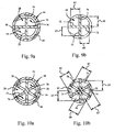
- FIGS. 7a and 7b show a measuring ring 44 having four detent areas 78 equally spaced 90 degrees apart from each other and a plunger 28 with one metering rib 74 and three uniform ribs 76.
- the measuring ring 44 latches onto the plunger 28 every quarter turn.
- This embodiment provides twice the number of dose intervals than the device that latches every half turn, and thus allows the device to meter out doses in relatively smaller dose increments.
- the plunger 28 may have multiple number of metering ribs 74.
- Figures 8a and 8b show a plunger 28 with four metering ribs 74 equally spaced 90 degrees apart and measuring ring 44 with one detent area 78. The measuring ring 44 still latches to the plunger 28 every quarter turn. Although it is preferable to use equally spaced detent areas and metering ribs to achieve repeatable incremental dose intervals, it is not required.
- Figures 9a and 9b (not according to the invention) show a plunger 28 with two metering ribs 74 at 0 degrees and 90 degrees respectively and a measuring ring 44 with two detent areas 78 and 90 degrees and 270 degrees respectively. The measuring ring 44 of this embodiment will also latch to the plunger 28 every quarter turn.
- the device can be configured to have multiple detent areas 78 and metering ribs 74.
- Figures 10a and 10b (not according to the invention) show a plunger 28 with three equally spaced metering ribs 74 and three equally spaced uniformed ribs 76, and a measuring ring 44 with two equally spaced detent areas 78.
- the measuring ring 44 of this embodiment will latch to the plunger 28 every sixth of a turn.
- the measuring ring 44 shown in the embodiment of Figure 5 has an outer surface with a pair of ribs 70, 72. Ribs 70, 72 are respectively disposed radially outwardly of the latches 50, 52 as an aid for lining up the ring 44 with the contacting outwardly of the latches 50, 52 as an aid for lining up the ring 44 with the contacting flange 29 of the plunger 28. In an alternate embodiment (not shown), painted markings or raised arrows may be used in place of the ribs 70 72.
- the measuring ring 44 may have a rough finish or rippled finish in place of the smooth finish on its outer surface; or the measuring ring 44 may have a plurality of equally angularly spaced ribs on its outer surface in addition to the ribs 70, 72 which have a painted marking.
Landscapes
- Health & Medical Sciences (AREA)
- Vascular Medicine (AREA)
- Engineering & Computer Science (AREA)
- Anesthesiology (AREA)
- Biomedical Technology (AREA)
- Heart & Thoracic Surgery (AREA)
- Hematology (AREA)
- Life Sciences & Earth Sciences (AREA)
- Animal Behavior & Ethology (AREA)
- General Health & Medical Sciences (AREA)
- Public Health (AREA)
- Veterinary Medicine (AREA)
- Infusion, Injection, And Reservoir Apparatuses (AREA)
Claims (2)
- Einstellbare Dosierungsspritze, umfassend:(a) einen hohlen Spritzenköper (12) mit einem Entladungs-Endabschnitt und einem gegenüberliegenden offenen Endabschnitt;(b) einen Tauchkolben (28), der im Spritzenköper durch den offenen Endabschnitt verschiebbar ist, wobei der Tauchkolben einen Kolbenkopf (34) aufweist, der innerhalb des Spritzenkörpers angebracht ist, und eine Dichtung, die darauf zwischen dem Tauchkolben und dem Inneren des Spritzenköpers gebildet ist, einschließt, wobei der Tauchkolben einen Schaft einschließt, der mit einem Außengewinde versehen ist; und(c) eine Gewindemutter (44) mit einem Innengewinde eines vorbestimmten Schrittes, die in das Außengewinde des Tauchkolbens eingreift, wobei die Gewindemutter weiter einen Innenumfang aufweist und dadurch gekennzeichnet, dass der Schaft mit vier Messrippen (74) versehen ist, wobei jede Messrippe eine Außenkante und einen Satz Kerben an der Außenkante aufweist, wobei der Satz Kerben auf jeder der Messrippen (74) das Außengewinde bildet, wobei jede der Messrippen weiter einen einklinkbaren kleineren Gewindedurchmesser aufweist, wobei die Gewindemutter (44) einen einzigen innen angebrachten Anschlagbereich (78) aufweist, um die Mutter in den Tauchkolben außerhalb des Spritzenköpers einzuklinken, wobei der Anschlagbereich (78) mit dem kleineren einklinkbaren Gewindedurchmesser jeder der Messrippen in Verwendung einklinkt, wobei eine Spritzendosis ohne die Notwendigkeit, den Schrittwinkel zu ändern, stufenweise einstellbar ist.
- Spritze nach Anspruch 1, wobei der Anschlagbereich (78) mit ersten und zweiten Vorsprüngen versehen ist.
Applications Claiming Priority (1)
| Application Number | Priority Date | Filing Date | Title |
|---|---|---|---|
| PCT/US1997/014135 WO1999007421A1 (en) | 1997-08-08 | 1997-08-08 | Incrementally adjustable dose syringe |
Publications (3)
| Publication Number | Publication Date |
|---|---|
| EP1009453A1 EP1009453A1 (de) | 2000-06-21 |
| EP1009453A4 EP1009453A4 (de) | 2001-01-10 |
| EP1009453B1 true EP1009453B1 (de) | 2006-11-29 |
Family
ID=22261433
Family Applications (1)
| Application Number | Title | Priority Date | Filing Date |
|---|---|---|---|
| EP97935342A Expired - Lifetime EP1009453B1 (de) | 1997-08-08 | 1997-08-08 | Stufenweise einstellbare dosierungsspritze |
Country Status (4)
| Country | Link |
|---|---|
| EP (1) | EP1009453B1 (de) |
| AU (1) | AU749996B2 (de) |
| DE (1) | DE69737038T2 (de) |
| WO (1) | WO1999007421A1 (de) |
Families Citing this family (5)
| Publication number | Priority date | Publication date | Assignee | Title |
|---|---|---|---|---|
| AR042539A1 (es) * | 2003-12-18 | 2005-06-22 | Jose Santiago Rolla | Unidad para suministro de inyectables en forma manual o automatica |
| SE535983C2 (sv) | 2010-04-20 | 2013-03-19 | Noviscens Ab | Spruta |
| US9872960B2 (en) | 2014-07-24 | 2018-01-23 | Teleflex Medical Incorporated | Dose divider syringe |
| CN107224638B (zh) * | 2017-07-20 | 2018-08-21 | 河北医科大学第二医院 | 一种医用避光注射器 |
| US20220339365A1 (en) * | 2019-09-30 | 2022-10-27 | Becton, Dickinson And Company | Medicament filling system |
Family Cites Families (10)
| Publication number | Priority date | Publication date | Assignee | Title |
|---|---|---|---|---|
| US3563240A (en) * | 1966-07-20 | 1971-02-16 | Jules Silver | Dual unit syringe |
| US4153056A (en) * | 1977-06-16 | 1979-05-08 | Jules Silver | Syringe with removable length adjusting member |
| US4246898A (en) * | 1979-07-23 | 1981-01-27 | Cutter Laboratories, Inc. | Syringe |
| US4275729A (en) * | 1979-10-29 | 1981-06-30 | Jules Silver | Adjustable dosage syringe |
| AR228395A1 (es) * | 1981-05-07 | 1983-02-28 | Merck & Co Inc | Jeringa para regular la cantidad suministrada de una sustancia plastica |
| US4654035A (en) * | 1985-09-12 | 1987-03-31 | Mitsubishi Pencil Co., Ltd. | Injector |
| FR2612782A1 (fr) * | 1987-03-23 | 1988-09-30 | Taddei Andre | Seringue d'injection a systeme de dosage |
| US4874385A (en) * | 1987-12-16 | 1989-10-17 | Sherwood Medical Company | Plunger lock device |
| US5344409A (en) * | 1993-06-14 | 1994-09-06 | Genesis Industries Inc. | Syringe latch |
| US5385558A (en) * | 1993-09-03 | 1995-01-31 | Maxxim Medical, Inc. | Angiographic control syringe |
-
1997
- 1997-08-08 EP EP97935342A patent/EP1009453B1/de not_active Expired - Lifetime
- 1997-08-08 DE DE69737038T patent/DE69737038T2/de not_active Expired - Lifetime
- 1997-08-08 AU AU38300/97A patent/AU749996B2/en not_active Expired
- 1997-08-08 WO PCT/US1997/014135 patent/WO1999007421A1/en not_active Ceased
Also Published As
| Publication number | Publication date |
|---|---|
| EP1009453A4 (de) | 2001-01-10 |
| EP1009453A1 (de) | 2000-06-21 |
| DE69737038D1 (de) | 2007-01-11 |
| DE69737038T2 (de) | 2007-06-21 |
| AU3830097A (en) | 1999-03-01 |
| AU749996B2 (en) | 2002-07-04 |
| WO1999007421A1 (en) | 1999-02-18 |
Similar Documents
| Publication | Publication Date | Title |
|---|---|---|
| US5344409A (en) | Syringe latch | |
| US4153056A (en) | Syringe with removable length adjusting member | |
| CA2932768C (en) | Dose divider syringe | |
| US4973318A (en) | Disposable syringe | |
| US6579269B1 (en) | Dosage device | |
| EP0074842B1 (de) | Vorrichtung zum Abgeben von einstellbaren Mengen eines Materials | |
| EP0058536B1 (de) | Dosiereinrichtung für eine Injektionsspritze | |
| US4367739A (en) | Syringe | |
| CN1315547C (zh) | 用于喷雾剂容器的显示装置 | |
| US4874385A (en) | Plunger lock device | |
| US5318544A (en) | Metering syringe | |
| AU2004266131C1 (en) | Medication dispensing apparatus with triple screw threads for mechanical advantage | |
| FI79247B (fi) | Handspruta. | |
| US20070265579A1 (en) | Dental syringe | |
| CN1243580C (zh) | 一种可调剂量注射器 | |
| US20080132852A1 (en) | Dosage device | |
| EP3171917B1 (de) | Dosisteiler-spritze | |
| US20040030299A9 (en) | Device for administering an injectable product | |
| AU749996B2 (en) | Incrementally adjustable dose syringe | |
| DD299156A5 (de) | Vorrichtung zur abgabe von mehrfachen kontrollierten dosen | |
| JP2013192936A (ja) | プレフィルドシリンジ用分注装置 | |
| EP0167501B1 (de) | Dosiereinrichtung für eine hypodermatische Spritze | |
| US20120197211A1 (en) | Medicine dispenser having a threaded plunger | |
| CN111939385A (zh) | 粘性且不可压缩的流体的注射器 | |
| CN112642023A (zh) | 可定量汲液的自毁式小剂量注射器 |
Legal Events
| Date | Code | Title | Description |
|---|---|---|---|
| PUAI | Public reference made under article 153(3) epc to a published international application that has entered the european phase |
Free format text: ORIGINAL CODE: 0009012 |
|
| 17P | Request for examination filed |
Effective date: 20000125 |
|
| AK | Designated contracting states |
Kind code of ref document: A1 Designated state(s): DE FR GB |
|
| A4 | Supplementary search report drawn up and despatched |
Effective date: 20001124 |
|
| AK | Designated contracting states |
Kind code of ref document: A4 Designated state(s): DE FR GB |
|
| 17Q | First examination report despatched |
Effective date: 20030207 |
|
| GRAP | Despatch of communication of intention to grant a patent |
Free format text: ORIGINAL CODE: EPIDOSNIGR1 |
|
| GRAS | Grant fee paid |
Free format text: ORIGINAL CODE: EPIDOSNIGR3 |
|
| GRAA | (expected) grant |
Free format text: ORIGINAL CODE: 0009210 |
|
| AK | Designated contracting states |
Kind code of ref document: B1 Designated state(s): DE FR GB |
|
| REG | Reference to a national code |
Ref country code: GB Ref legal event code: FG4D |
|
| REF | Corresponds to: |
Ref document number: 69737038 Country of ref document: DE Date of ref document: 20070111 Kind code of ref document: P |
|
| ET | Fr: translation filed | ||
| PLBE | No opposition filed within time limit |
Free format text: ORIGINAL CODE: 0009261 |
|
| STAA | Information on the status of an ep patent application or granted ep patent |
Free format text: STATUS: NO OPPOSITION FILED WITHIN TIME LIMIT |
|
| 26N | No opposition filed |
Effective date: 20070830 |
|
| PGFP | Annual fee paid to national office [announced via postgrant information from national office to epo] |
Ref country code: DE Payment date: 20130731 Year of fee payment: 17 |
|
| PGFP | Annual fee paid to national office [announced via postgrant information from national office to epo] |
Ref country code: FR Payment date: 20130808 Year of fee payment: 17 Ref country code: GB Payment date: 20130807 Year of fee payment: 17 |
|
| REG | Reference to a national code |
Ref country code: DE Ref legal event code: R119 Ref document number: 69737038 Country of ref document: DE |
|
| GBPC | Gb: european patent ceased through non-payment of renewal fee |
Effective date: 20140808 |
|
| REG | Reference to a national code |
Ref country code: FR Ref legal event code: ST Effective date: 20150430 |
|
| PG25 | Lapsed in a contracting state [announced via postgrant information from national office to epo] |
Ref country code: DE Free format text: LAPSE BECAUSE OF NON-PAYMENT OF DUE FEES Effective date: 20150303 Ref country code: GB Free format text: LAPSE BECAUSE OF NON-PAYMENT OF DUE FEES Effective date: 20140808 |
|
| PG25 | Lapsed in a contracting state [announced via postgrant information from national office to epo] |
Ref country code: FR Free format text: LAPSE BECAUSE OF NON-PAYMENT OF DUE FEES Effective date: 20140901 |