EP1009556B1 - Abkantpresse zur herstellung u-förmiger abkantungen an den kanten eines tafelblehes - Google Patents
Abkantpresse zur herstellung u-förmiger abkantungen an den kanten eines tafelblehes Download PDFInfo
- Publication number
- EP1009556B1 EP1009556B1 EP98920517A EP98920517A EP1009556B1 EP 1009556 B1 EP1009556 B1 EP 1009556B1 EP 98920517 A EP98920517 A EP 98920517A EP 98920517 A EP98920517 A EP 98920517A EP 1009556 B1 EP1009556 B1 EP 1009556B1
- Authority
- EP
- European Patent Office
- Prior art keywords
- holder
- shoe
- blank
- press
- slide
- Prior art date
- Legal status (The legal status is an assumption and is not a legal conclusion. Google has not performed a legal analysis and makes no representation as to the accuracy of the status listed.)
- Expired - Lifetime
Links
- 238000005452 bending Methods 0.000 title claims abstract description 26
- 239000002184 metal Substances 0.000 title claims abstract description 15
- 230000008707 rearrangement Effects 0.000 claims abstract description 6
- 230000006835 compression Effects 0.000 claims description 3
- 238000007906 compression Methods 0.000 claims description 3
- 230000015572 biosynthetic process Effects 0.000 claims 1
- 238000003780 insertion Methods 0.000 claims 1
- 230000037431 insertion Effects 0.000 claims 1
- 230000007246 mechanism Effects 0.000 abstract description 4
- 238000004519 manufacturing process Methods 0.000 description 4
- 230000001419 dependent effect Effects 0.000 description 1
- 230000000694 effects Effects 0.000 description 1
Images


Classifications
-
- B—PERFORMING OPERATIONS; TRANSPORTING
- B21—MECHANICAL METAL-WORKING WITHOUT ESSENTIALLY REMOVING MATERIAL; PUNCHING METAL
- B21D—WORKING OR PROCESSING OF SHEET METAL OR METAL TUBES, RODS OR PROFILES WITHOUT ESSENTIALLY REMOVING MATERIAL; PUNCHING METAL
- B21D5/00—Bending sheet metal along straight lines, e.g. to form simple curves
- B21D5/04—Bending sheet metal along straight lines, e.g. to form simple curves on brakes making use of clamping means on one side of the work
- B21D5/045—With a wiping movement of the bending blade
-
- B—PERFORMING OPERATIONS; TRANSPORTING
- B21—MECHANICAL METAL-WORKING WITHOUT ESSENTIALLY REMOVING MATERIAL; PUNCHING METAL
- B21D—WORKING OR PROCESSING OF SHEET METAL OR METAL TUBES, RODS OR PROFILES WITHOUT ESSENTIALLY REMOVING MATERIAL; PUNCHING METAL
- B21D5/00—Bending sheet metal along straight lines, e.g. to form simple curves
- B21D5/04—Bending sheet metal along straight lines, e.g. to form simple curves on brakes making use of clamping means on one side of the work
Definitions
- the present invention relates to a bending press for forming at least one bend in an edge of a metal sheet, according to the preamble to Claim 1.
- a bending press according to the preamble to Claim 1 is known from the document WO 96/13346.
- a bending press according to one embodiment described and illustrated in the document WO 96/13346 comprises a pair of carriages which can be moved along its movable blank-holder in order to rearrange its segments.
- Each of these carriages comprises a first set of teeth fixed to the carriage, an input shaft housed in the shoe-holder body and connected to the first set of teeth by a toothed sprocket, a second set of teeth fixed to the shoe, and gearing for transmitting the drive of the input shaft to the second set of teeth.
- This known mechanism enables the movements of the two shoes to be coordinated with the movements of the movable blank-holder, preferably by numerical control, in a manner such that, for movements of the movable blank-holder away from the fixed blank-holder there are corresponding simultaneous movements of the two shoes towards the centre of the press and towards the fixed blank-holder, without sliding of the shoes on the sheet.
- the two shoes are returned to the position in which they are moved away from the centre of the press by means of respective spiral springs or equivalent means incorporated in the shoe-holder body and interposed between it and the input shaft of the mechanism.
- the object of the invention is to provide a bending press of the type .in question in which the function of controlling the movements of the shoes is performed by much simpler and more inexpensive means.
- the devices which transmit the movement of the carriages to the shoes in order to move them towards the centre of the press and towards the fixed blank-holder, that is, in order to release them from the channel-shaped bends without sliding on the sheet do not comprise toothed members requiring very precise manufacture.
- these devices comprise very simple elements which operate by pressure and by relative sliding; even though the cooperating surfaces of these elements require a certain precision of manufacture, this precision does not involve such high costs as the manufacture of teeth.
- the embodiment shown in the drawings relates to the most common case of a press in which the movable blank-holder is the upper one, the fixed blank-holder is the lower one, and the plane of the metal sheet subjected to bending is horizontal.
- the invention is not limited to this arrangement, however, since, by virtue of the fact that the movements of the shoes are brought about positively, it can be applied to other arrangements such as, for example, an arrangement in which the movable blank-holder is the lower one, or an arrangement in which the plane of the metal sheet is vertical and the movable blank-holder moves horizontally.
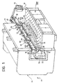
- a vertical bending press generally indicated 10, comprises a strong channel-shaped frame, generally indicated 12.
- a strong front plate 14 is slidable vertically on an upper front portion of the frame 12 and its lower portion carries an upper movable blank-holder, generally indicated 16, which will be referred to further below.
- a lower front portion of the frame 12 carries a fixed blank-holder 18 with which the movable blank-holder 16 cooperates during bending operations.
- a blade-holder 20 mounted in the cavity defined by the channel-shape of the frame 12 is also channel-shaped and carries a pair of bending blades, that is, a lower blade 22 and an upper blade 24.
- the blade-holder 20 can be moved upwards and downwards and also advanced and retracted under the control of actuators which are preferably numerically controlled, in order selectively to cause its lower blade 22 to cooperate with the upper blank-holder 16 or its upper blade 24 with the lower blank-holder 18.
- the upper movable blank-holder 16 is of the sectional type formed by a series of segments 26, for example, as in the bending presses described and illustrated in the documents US-A-4 089 198 and WO 96/13346.
- the series of segments 26 comprises two special segments, indicated 28, which are spaced apart so as to correspond to opposite lateral edges of a metal sheet.
- these segments 28 are arranged at the two ends of the series of segments, that is, in positions corresponding to the maximum useful width of the press.
- a table 30 for supporting metal sheets being bent As shown in Figure 1, on the front of the press 10 there is a table 30 for supporting metal sheets being bent.
- the table 30 is preferably served by a manipulator (not shown).
- All of the movements of the press and of its manipulator are preferably controlled by a numerical control device, conventionally indicated by means of a suspended "console" 32 thereof.
- a translation bar 34 extending along the movable blank-holder 16 comprises two portions 38 which are threaded in opposite directions.
- the bar 34 can be rotated selectively by a numerically-controlled electric motor 40.
- the two portions 38 of the bar 34 which are threaded in opposite directions carry respective carriages 42 coupled to these threaded portions by means of respective female threads, not shown.
- the two carriages 42 are provided for rearranging the segments 26 of the movable blank-holder 16 each time such rearrangement is necessary in order to adapt the blank-holder 16 to the width of a specific sheet to be bent.
- each carriage 42 has a respective entraining member 44, further details of which will be given below.
- each of the segments 26 has a respective entrained member constituted by a front projection 46 which can be engaged by a respective entraining member 44.
- each end segment 28 comprises a shoe-holder body 48 which acts as the actual segment and has, for its rearrangement by the respective carriage 42, an entrained member 46a in the form of a front projection just like the projections 46 and aligned therewith.
- Each body 48 supports a shoe 50 with a lower beak-like projection 52.
- each shoe 50 extends in opposite directions so that each can be inserted in a lateral channel-shaped bend, indicated B, already formed in a metal sheet P.
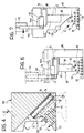
- Each shoe 50 is supported by its body 48 by means of inclined guides 54, preferably oriented at 45° to the plane of the metal sheet P ( Figures 8 to 10) to be bent.
- Each shoe 50 can move along the guides 54 between a working or engagement position, shown in continuous outline in Figures 2 and 4 as well as in Figure 6, and a release position, shown in broken outline in Figures 2 and 4, as well as in Figure 7.
- Each shoe-holder body 48 carries a respective slide 56 slidable on the body 48 in directions parallel to the directions of movement of the carriage 42.
- An abutment in the form of a block 58 is fixed to the slide 56 so as to be adjustable in the same directions.
- a driving portion 60 in the form of a vertically elongate plate-like portion is fixed to the slide 56.
- the plate-like portion 60 is fitted flat on a front face of the shoe-holder body 28 and is substantially coplanar with the front faces of the segments 26.
- Each shoe 50 has a driven portion 64 fixed thereto.
- the driven portion 64 is constituted by a plate fixed to the front of the shoe 50 by means of a series of screws 66, the heads of which are shown schematically in Figures 6 and 7.
- a straight lateral edge of the plate 64, indicated 68, is parallel to and faces the straight edge 62.
- the two edges 62 and 68 constitute facing cooperating pressure and sliding surfaces arranged in a manner such that a movement of the slide 56 towards the centre of the press is converted by the cooperation of the facing surfaces 62, 68 with pressure and sliding into a movement of the shoe 50 from the working position of Figure 6 to the release position of Figure 7.
- a resilient biasing means is provided for returning the shoe 50 from the release position to the working position.
- each shoe-holder body 48 has a recess 70 also visible in Figures 2, 3 and 5.
- This recess 70 extends parallel to the inclined guides 54 and contains, as resilient biasing means, at least one helical compression biasing spring 72.
- the shoe 50 has an appendage 74, also visible in Figures 2, 3 and 5, which is slidable along a fixed rod 76 extending through the spring 70 for centring purposes.
- the spring 70 reacts against an end wall 78 of the cavity 70 at one end and against the appendage 74 at the other end.
- the entraining member 44 is in the form of a bar slidable vertically, that is, in the direction of movement of the movable blank-holder 16, in the respective carriage 42.
- the top of the bar 44 is connected to the rod of a respective linear actuator 80 ( Figure 1), which is preferably numerically controlled.
- the actuator 80 can move the bar between a position in which it is raised, that is, retracted, relative to the fixed blank-holder 18, an intermediate position, and a position in which it is lowered, that is, advanced relative to the fixed blank-holder 18.
- the bar 44 is so arranged as to interfere with the projection or abutment 58 of the slide 56 on its side facing outwardly relative to the press.
- the edge 62 of the driving member constituted by the plate-shaped portion 60 of the slide 56 engages the edge 68 of the plate 64 of the shoe 50.
- the arrangement is such that, when the shoe 50 reaches the release position of Figure 7, the bar 44 strikes the projection 46a which constitutes a travel-limit stop.
- This travel-limit position can be adjusted by adjustment of the position of the abutment or projection 58 along the slide 56.
- the metal sheet P is gripped between the upper blank-holder 16 and the lower blank-holder 18.
- the two shoes 50 are in the respective working positions of Figure 6 in which they are moved apart and away from the centre of the press and their beak-like projections 52 are fitted in the respective lateral bends B in the sheet P.
- the numerical control device 32 brings about upward movement of the movable blank-holder 16 and, at the same time, oblique movement of the two shoes 50 towards their release positions in the direction of the arrow G of Figure 7.
- the movements are coordinated in a manner such that, as soon as the movable blank-holder 16 is detached from the sheet P, the shoes 50 are also detached from the sheet P whilst starting to move in the direction of the arrow G of Figure 7, so that they never slide on the panel.
- Figure 10 shows the final condition in which the movable blank-holder 16 is raised and the shoes 50 are moved the maximum distance towards one another and have reached the final release position of Figure 7. In this position, the projections 52 no longer interfere with the bends B.
- Figure 1 shows a bending press which comprises a pair of blades cooperating with respective opposed blades forming part of respective blank-holders.
- the invention may, however, be applied to a press even having only one pair of bending tools (blade and opposed blade), in particular in order to form one or more bends in an edge of a metal sheet in a direction perpendicular to that of the opposed channel-shaped bends indicated B in Figures 8 to 10.
Landscapes
- Engineering & Computer Science (AREA)
- Mechanical Engineering (AREA)
- Bending Of Plates, Rods, And Pipes (AREA)
- Shaping Of Tube Ends By Bending Or Straightening (AREA)
- Presses And Accessory Devices Thereof (AREA)
Claims (7)
- Abkantpresse zum Bilden mindestens einer Abkantung an einer Kante eines Metallblechs, von dem mindestens eine Seitenkante, lotrecht zur abzukantenden Kante, bereits in eine U-Form gebogen worden ist, der Art, die ein Paar einander gegenüberliegende Niederhalter, das heißt einen beweglichen Niederhalter (16) und einen fixierten Niederhalter (18), und mindestens ein Biegeblatt (22), das mit dem beweglichen Niederhalter (16) zusammenwirkt, umfasst, wobei:dadurch gekennzeichnet, dassder bewegliche Niederhalter (16) eine Reihe von Segmenten (26, 28) umfasst, die entlang des Niederhalters beweglich und mit einem Paar motorbetriebene Schlitten (42) ausgestattet sind, von denen jeder ein Mitnahmeglied (44) aufweist, das wahlweise die Segmente (26, 28) in und außer Eingriff bringen kann, um sie zu Umordnungszwecken zu bewegen,jedes von zwei Segmenten (28), die sich an entgegengesetzten Enden der Reihe befinden, einen Schuhhalterbauteil (48) umfasst, der einen jeweiligen Schuh (50) trägt, und zwar mittels geneigter Führungen (54), die hin zum fixierten Niederhalter (18) konvergieren,die zwei Schuhe (50) Fortsätze (52) aufweisen, die sich in entgegengesetzten Richtungen erstrecken, und zwar zum Einsetzen in jeweilige U-förmige Abkantungen (B), die bereits gebildet worden sind,jeder Schlitten (42) eine Bewegung eines jeweiligen Schuhs (50) entlang seiner geneigten Führungen (54) in einer Richtung hin zur Mitte der Presse (10) und hin zum fixierten Niederhalter (18) herbeiführen kann, während sich der bewegliche Niederhalter (16) vom fixierten Niederhalter (18) nach der Bildung der Abkantung fortbewegt, unddie Schuhe (50) jeweilige Mittel (72) aufweisen, um sie elastisch auf eine Seite zu lenken, und zwar weg von der Mitte der Presse (10) und vom beweglichen Niederhalter (16),jeder Schuhhalterbauteil (48) einen jeweiligen Schieber (56) trägt, der parallel zur Bewegungsrichtung des jeweiligen Schlittens (42) beweglich ist,jeder Schieber (56) einen antreibenden Teil (60) und jeder Schuh (50) einen angetriebenen Teil (64) aufweist, wobei der antreibende Teil und der angetriebene Teil einander zugewandte, zusammenwirkende Druck- und Gleitoberflächen (62, 68) aufweisen, die solcherart angeordnet sind, dass eine Bewegung des Schiebers (56) hin zur Mitte der Presse (10) durch das Zusammenwirken der einander zugewandten Oberflächen (62, 68) mit Druck und Gleiten in eine Schrägbewegung des jeweiligen Schuhs (50) entlang der jeweiligen geneigten Führung (54) hin zur Mitte der Presse (10) und hin zum fixierten Niederhalter (18) umgewandelt wird,jeder Schlitten (42) ein mitnehmendes Glied (44) und jeder Schieber (56) ein mitgenommenes Glied (58) umfasst, das durch das mitnehmende Glied (44) des jeweiligen Schlittens (42) in Eingriff gebracht werden kann, um den Schieber (56) wahlweise hin zur Mitte der Presse (10) zu bewegen, unddie zwei Schlitten (42) auf Befehl gleichzeitig in entgegengesetzte Richtungen beweglich sind, um die vorgenannten Bewegungen der Schuhe (50) mittels der Schieber (56) gleichzeitig herbeizurühren.
- Abkantpresse nach Anspruch 1, dadurch gekennzeichnet, dass jeder Schlitten (42) ein einzelnes mitnehmendes Glied (44) umfasst, und zwar zum wahlweisen Bewegen der Segmente (26, 28) zu Umordnungszwecken und zum In-Eingriff-Bringen des mitgenommenen Glieds (58) eines jeweiligen Schiebers (56), um ihn hin zur Mitte der Presse (10) zu bewegen.
- Abkantpresse nach Anspruch 2, dadurch gekennzeichnet, dass das mitnehmende Glied jedes Schlittens (42) von einem Stab (44) gebildet wird, der sich in der Bewegungsrichtung des beweglichen Niederhalters (16) erstreckt und der durch ein jeweiliges Stellglied (80) in dieser Richtung beweglich ist, und zwar zwischen einer Stellung (L1), in der er im Verhältnis zum fixierten Niederhalter (18) eingefahren ist, einer Zwischenstellung (L2) und einer Stellung (L3), in der er im Verhältnis zum fixierten Niederhalter (18) ausgefahren ist, dass jedes Segment (26, 28) einen ersten vorderen Fortsatz (46) aufweist, der durch den Stab (44) zu Zwecken der Umordnung der Segmente (26, 28) seitlich in Eingriff gebracht werden kann, dass jeder Schieber (56) einen zweiten vorderen Fortsatz (58) aufweist, der durch den Stab (44) des jeweiligen Schlittens (42) zum Zwecke des Bewegens des Schiebers (56) in der Richtung, die der Bewegung des Schuhs (50) nach innen entspricht, seitlich in Eingriff gebracht werden kann, und dass die Anordnung des Stabs (44) und der Fortsätze (46, 46a, 58) so ist, dass der Stab (44) in seiner Zwischenstellung (L2) lediglich die Fortsätze (46, 46a) der Segmente (26, 28) in Eingriff bringen kann, einschließlich des Fortsatzes (46a) des jeweiligen Schuhhalterbauteils (28), und der Stab (44) in der ausgefahrenen Stellung (L3) den Fortsatz (58) des jeweiligen Schiebers (56) in Eingriff bringen kann.
- Abkantpresse nach Anspruch 3, dadurch gekennzeichnet, dass dann, wenn der Schieber (56) in der von der Mitte der Presse (10) am weitesten entfernten Stellung ist, sein Fortsatz (58) weiter von der Mitte als der Fortsatz (46a) des Schuhhalterbauteils (28) entfernt ist, und der Fortsatz (46a) des Schuhhalterbauteils (28) so angeordnet ist, dass er in der Richtung, in der sich der bewegliche Niederhalter (16) erstreckt, einen seitlichen Weganschlag für den Stab (44) bildet, und zwar in der Stellung des Schiebers (56), die der Stellung entspricht, in der der Schuh (50) hin zum fixierten Niederhalter (18) und hin zur Mitte der Presse (10) bewegt wird.
- Abkantpresse nach einem der vorstehenden Ansprüche, dadurch gekennzeichnet, dass der angetriebene Teil von einer Platte (64) gebildet wird, die an der Vorderseite des jeweiligen Schuhs (50) befestigt ist und als zugewandte Oberfläche eine gerade Kante (68) aufweist, die sich in der Bewegungsrichtung des beweglichen Niederhalters (16) erstreckt, lotrecht zur Bewegungsrichtung des Schiebers (56), und im Verhältnis zur Presse (10) seitlich nach außen geht, und der jeweilige antreibende Teil von einem plattenähnlichen Teil (60) gebildet wird, der aus dem Schlitten (42) herausragt, koplanar mit der am Schuh (50) befestigten Platte (64), und als zugewandte Oberfläche eine gerade Kante (62) aufweist, die parallel zur geraden Kante (68) der am Schuh (50) befestigten Platte (64) ist und im Verhältnis zur Presse (10) seitlich nach innen geht.
- Abkantpresse nach einem der vorstehenden Ansprüche, dadurch gekennzeichnet, dass jedes elastische, auf eine Seite wirkende Mittel mindestens eine auf eine Seite wirkende Druck-Schraubenfeder (72) umfasst, die sich parallel zur geneigten Führung (54) erstreckt, in einer Aussparung (70) im Schuhhalterbauteil (48) untergebracht ist und am einen Ende gegen eine Endwand (78) der Aussparung (70) und am anderen Ende gegen einen Überstand (74) des Schuhs (50) wirkt.
- Abkantpresse nach einem der Ansprüche 3 bis 6, dadurch gekennzeichnet, dass sie einen mit einem Gewinde versehenen Übertragungsstab (34) umfasst, der sich entlang des beweglichen Niederhalters (16) erstreckt und zwei Teile (38) aufweist, die in entgegengesetzten Richtungen mit einem Gewinde versehen und mit jeweiligen Innengewinden der jeweiligen Schlitten (42) gekoppelt sind, sowie einen nummerisch gesteuerten Elektromotor (40) zum Drehen des mit einem Gewinde versehenen Stabs (44), dass jeder Schlitten (42) ein nummerisch gesteuertes Stellglied (80) zum Bewegen des jeweiligen Stabs (44) trägt und dass die Abkantpresse eine nummerische Steuerungseinheit (32) umfasst, die den Motor (40) und die Stellglieder (80) in Koordination mit den Mitteln zum Steuern des beweglichen Niederhalters (16) so steuert, dass es für Bewegungen des beweglichen Niederhalters (16) weg vom fixierten Niederhalter (18) und hin zu ihm jeweilige entsprechende Bewegungen der Schuhe (50) hin zueinander und weg voneinander gibt, und zwar ohne Gleiten der Schuhe auf dem zwischen den zwei Niederhaltern (16, 18) angeordneten Metallblech.
Applications Claiming Priority (3)
| Application Number | Priority Date | Filing Date | Title |
|---|---|---|---|
| ITTO970315 | 1997-04-15 | ||
| IT97TO000315A IT1292260B1 (it) | 1997-04-15 | 1997-04-15 | Pressa piegatrice per l'esecuzione di pieghe a c sui bordi di un pannello di lamiera. |
| PCT/EP1998/002162 WO1998046379A1 (en) | 1997-04-15 | 1998-04-14 | A bending press for forming channel-shaped bends in the edges of a metal sheet |
Publications (2)
| Publication Number | Publication Date |
|---|---|
| EP1009556A1 EP1009556A1 (de) | 2000-06-21 |
| EP1009556B1 true EP1009556B1 (de) | 2002-03-13 |
Family
ID=11415643
Family Applications (1)
| Application Number | Title | Priority Date | Filing Date |
|---|---|---|---|
| EP98920517A Expired - Lifetime EP1009556B1 (de) | 1997-04-15 | 1998-04-14 | Abkantpresse zur herstellung u-förmiger abkantungen an den kanten eines tafelblehes |
Country Status (9)
| Country | Link |
|---|---|
| US (1) | US6170314B1 (de) |
| EP (1) | EP1009556B1 (de) |
| JP (1) | JP2001519718A (de) |
| AT (1) | ATE214311T1 (de) |
| CA (1) | CA2285555A1 (de) |
| DE (1) | DE69804227T2 (de) |
| ES (1) | ES2173576T3 (de) |
| IT (1) | IT1292260B1 (de) |
| WO (1) | WO1998046379A1 (de) |
Families Citing this family (10)
| Publication number | Priority date | Publication date | Assignee | Title |
|---|---|---|---|---|
| NL1017719C2 (nl) * | 2001-03-28 | 2002-10-01 | Cornelis Hendricus Liet | Inrichting voor het buigen van een metaalplaat. |
| ES2229879B1 (es) * | 2003-02-20 | 2006-02-16 | Goiti, S. Coop. | Maquina plegadora de chapas perfeccionada. |
| US7100418B2 (en) * | 2004-11-22 | 2006-09-05 | Jeske Christopher D | Metal shaping apparatus |
| JP1539124S (de) * | 2014-08-15 | 2015-11-30 | ||
| USD755861S1 (en) * | 2014-08-15 | 2016-05-10 | Trumpf Gmbh + Co. Kg | Bending machine |
| CN105458106B (zh) * | 2016-01-13 | 2017-11-28 | 江苏比微曼智能科技有限公司 | 一种可快速更换的压角块 |
| CN108637088B (zh) * | 2018-03-15 | 2019-08-30 | 安徽凯贝耐特钣金科技有限公司 | 一种多卡边面板的卡边折弯工装及折弯方法 |
| CN108723242B (zh) * | 2018-05-04 | 2024-06-07 | 苏州沃特维自动化系统有限公司 | 用于汇流焊接引线的折弯装置 |
| CN116944289B (zh) * | 2023-03-24 | 2025-12-02 | 佛山市南海力钏冷轧机械有限公司 | 一种适用于折弯机中心的拼刀装置及使用方法 |
| CN118268426B (zh) * | 2024-04-09 | 2026-02-17 | 东锻机械(广东)有限公司 | 具有新型传动机构的折弯中心 |
Family Cites Families (4)
| Publication number | Priority date | Publication date | Assignee | Title |
|---|---|---|---|---|
| JPS61159224A (ja) * | 1984-12-29 | 1986-07-18 | Maru Kikai Kogyo Kk | プレスブレ−キの型長さ変換装置 |
| US5313814A (en) * | 1992-10-27 | 1994-05-24 | Kabushiki Kaisha Komatsu Seisakusho | Bending machine |
| IT1267842B1 (it) * | 1994-07-27 | 1997-02-18 | Sapim Amada Spa | Premilamiera ad allestimento variabile |
| IT1267472B1 (it) * | 1994-10-27 | 1997-02-05 | Sapim Amada Spa | Pressa piegatrice per l'esecuzione di pieghe a c sui quattro bordi di un pannello di lamiera. |
-
1997
- 1997-04-15 IT IT97TO000315A patent/IT1292260B1/it active IP Right Grant
-
1998
- 1998-04-14 US US09/402,925 patent/US6170314B1/en not_active Expired - Lifetime
- 1998-04-14 EP EP98920517A patent/EP1009556B1/de not_active Expired - Lifetime
- 1998-04-14 CA CA002285555A patent/CA2285555A1/en not_active Abandoned
- 1998-04-14 DE DE69804227T patent/DE69804227T2/de not_active Expired - Lifetime
- 1998-04-14 WO PCT/EP1998/002162 patent/WO1998046379A1/en not_active Ceased
- 1998-04-14 ES ES98920517T patent/ES2173576T3/es not_active Expired - Lifetime
- 1998-04-14 JP JP54348698A patent/JP2001519718A/ja active Pending
- 1998-04-14 AT AT98920517T patent/ATE214311T1/de not_active IP Right Cessation
Also Published As
| Publication number | Publication date |
|---|---|
| DE69804227T2 (de) | 2002-10-10 |
| US6170314B1 (en) | 2001-01-09 |
| CA2285555A1 (en) | 1998-10-22 |
| ES2173576T3 (es) | 2002-10-16 |
| ITTO970315A1 (it) | 1998-10-15 |
| JP2001519718A (ja) | 2001-10-23 |
| IT1292260B1 (it) | 1999-01-29 |
| ATE214311T1 (de) | 2002-03-15 |
| EP1009556A1 (de) | 2000-06-21 |
| WO1998046379A1 (en) | 1998-10-22 |
| DE69804227D1 (de) | 2002-04-18 |
Similar Documents
| Publication | Publication Date | Title |
|---|---|---|
| EP1009556B1 (de) | Abkantpresse zur herstellung u-förmiger abkantungen an den kanten eines tafelblehes | |
| EP1009557B1 (de) | Biegepresse für metallblech | |
| EP1015148B1 (de) | Biegepresse zur herstellung von kanalförmigen biegungen an den kanten eines bleches | |
| GB2226516A (en) | Sheet metal bending press | |
| CN112692117A (zh) | 一种直角折弯装置及工艺 | |
| US4347727A (en) | Programmable upward-stroke insert mechanism for bending brakes and method of use | |
| EP0788411B1 (de) | Abkantpresse zur herstellung u-foermiger abkantungen an den vier kanten eines tafelbleches | |
| US5794481A (en) | Device for bending or curving hollow-section strips | |
| CN208840246U (zh) | 一种折弯机数控挡指装置 | |
| CN209935665U (zh) | 悬臂式切断弯折一体机 | |
| CN118558799A (zh) | 一种冷柜机箱钣金加工用全自动弯折成型设备 | |
| CN215998460U (zh) | 一种压紧装置及弯曲机 | |
| CN211100918U (zh) | 一种多边折弯机 | |
| JPH0824964B2 (ja) | 折曲げ機のバックゲージ装置 | |
| EP1493508B1 (de) | Antrieb für eine Vorrichtung zum Krimpen, insbesondere zum Krimpen des Randes eines Kraftfahrzeugfensters | |
| CN205496341U (zh) | 一种钣金成型的折弯定位夹紧结构 | |
| WO1996032214A1 (en) | Device for setting the position of a metal sheet in a bending press, and bending press comprising this device | |
| CN218425231U (zh) | 便于调节夹紧间距的折弯机挡料机构 | |
| CN213436446U (zh) | 一种折弯机挡料装置 | |
| KR102540079B1 (ko) | 판재의 루프벤딩장치 | |
| CN216632135U (zh) | 一种新型左右折弯机头 | |
| CN219724187U (zh) | 一种五金折弯机 | |
| KR102349432B1 (ko) | 캠 드라이브 좌우 이동식 재질 공용화가 가능한 벤딩 금형 | |
| CN214324669U (zh) | 一种自动订书设备 | |
| CN117619954A (zh) | 一种折弯角度可调的金具折弯机及其使用方法 |
Legal Events
| Date | Code | Title | Description |
|---|---|---|---|
| PUAI | Public reference made under article 153(3) epc to a published international application that has entered the european phase |
Free format text: ORIGINAL CODE: 0009012 |
|
| 17P | Request for examination filed |
Effective date: 19991112 |
|
| AK | Designated contracting states |
Kind code of ref document: A1 Designated state(s): AT BE CH DE DK ES FR GB GR IE IT LI NL PT SE |
|
| GRAG | Despatch of communication of intention to grant |
Free format text: ORIGINAL CODE: EPIDOS AGRA |
|
| 17Q | First examination report despatched |
Effective date: 20010427 |
|
| GRAG | Despatch of communication of intention to grant |
Free format text: ORIGINAL CODE: EPIDOS AGRA |
|
| GRAH | Despatch of communication of intention to grant a patent |
Free format text: ORIGINAL CODE: EPIDOS IGRA |
|
| GRAH | Despatch of communication of intention to grant a patent |
Free format text: ORIGINAL CODE: EPIDOS IGRA |
|
| REG | Reference to a national code |
Ref country code: GB Ref legal event code: IF02 |
|
| GRAA | (expected) grant |
Free format text: ORIGINAL CODE: 0009210 |
|
| AK | Designated contracting states |
Kind code of ref document: B1 Designated state(s): AT BE CH DE DK ES FR GB GR IE IT LI NL PT SE |
|
| PG25 | Lapsed in a contracting state [announced via postgrant information from national office to epo] |
Ref country code: NL Free format text: LAPSE BECAUSE OF FAILURE TO SUBMIT A TRANSLATION OF THE DESCRIPTION OR TO PAY THE FEE WITHIN THE PRESCRIBED TIME-LIMIT Effective date: 20020313 Ref country code: LI Free format text: LAPSE BECAUSE OF FAILURE TO SUBMIT A TRANSLATION OF THE DESCRIPTION OR TO PAY THE FEE WITHIN THE PRESCRIBED TIME-LIMIT Effective date: 20020313 Ref country code: GR Free format text: LAPSE BECAUSE OF FAILURE TO SUBMIT A TRANSLATION OF THE DESCRIPTION OR TO PAY THE FEE WITHIN THE PRESCRIBED TIME-LIMIT Effective date: 20020313 Ref country code: CH Free format text: LAPSE BECAUSE OF FAILURE TO SUBMIT A TRANSLATION OF THE DESCRIPTION OR TO PAY THE FEE WITHIN THE PRESCRIBED TIME-LIMIT Effective date: 20020313 Ref country code: BE Free format text: LAPSE BECAUSE OF FAILURE TO SUBMIT A TRANSLATION OF THE DESCRIPTION OR TO PAY THE FEE WITHIN THE PRESCRIBED TIME-LIMIT Effective date: 20020313 Ref country code: AT Free format text: LAPSE BECAUSE OF FAILURE TO SUBMIT A TRANSLATION OF THE DESCRIPTION OR TO PAY THE FEE WITHIN THE PRESCRIBED TIME-LIMIT Effective date: 20020313 |
|
| REF | Corresponds to: |
Ref document number: 214311 Country of ref document: AT Date of ref document: 20020315 Kind code of ref document: T |
|
| REG | Reference to a national code |
Ref country code: CH Ref legal event code: EP |
|
| PG25 | Lapsed in a contracting state [announced via postgrant information from national office to epo] |
Ref country code: IE Free format text: LAPSE BECAUSE OF NON-PAYMENT OF DUE FEES Effective date: 20020415 |
|
| REF | Corresponds to: |
Ref document number: 69804227 Country of ref document: DE Date of ref document: 20020418 |
|
| PG25 | Lapsed in a contracting state [announced via postgrant information from national office to epo] |
Ref country code: SE Free format text: LAPSE BECAUSE OF FAILURE TO SUBMIT A TRANSLATION OF THE DESCRIPTION OR TO PAY THE FEE WITHIN THE PRESCRIBED TIME-LIMIT Effective date: 20020613 Ref country code: DK Free format text: LAPSE BECAUSE OF FAILURE TO SUBMIT A TRANSLATION OF THE DESCRIPTION OR TO PAY THE FEE WITHIN THE PRESCRIBED TIME-LIMIT Effective date: 20020613 |
|
| PG25 | Lapsed in a contracting state [announced via postgrant information from national office to epo] |
Ref country code: PT Free format text: LAPSE BECAUSE OF FAILURE TO SUBMIT A TRANSLATION OF THE DESCRIPTION OR TO PAY THE FEE WITHIN THE PRESCRIBED TIME-LIMIT Effective date: 20020614 |
|
| NLV1 | Nl: lapsed or annulled due to failure to fulfill the requirements of art. 29p and 29m of the patents act | ||
| ET | Fr: translation filed | ||
| REG | Reference to a national code |
Ref country code: CH Ref legal event code: PL |
|
| REG | Reference to a national code |
Ref country code: ES Ref legal event code: FG2A Ref document number: 2173576 Country of ref document: ES Kind code of ref document: T3 |
|
| PLBE | No opposition filed within time limit |
Free format text: ORIGINAL CODE: 0009261 |
|
| STAA | Information on the status of an ep patent application or granted ep patent |
Free format text: STATUS: NO OPPOSITION FILED WITHIN TIME LIMIT |
|
| REG | Reference to a national code |
Ref country code: IE Ref legal event code: MM4A |
|
| 26N | No opposition filed |
Effective date: 20021216 |
|
| PGFP | Annual fee paid to national office [announced via postgrant information from national office to epo] |
Ref country code: ES Payment date: 20040317 Year of fee payment: 7 |
|
| PGFP | Annual fee paid to national office [announced via postgrant information from national office to epo] |
Ref country code: GB Payment date: 20050314 Year of fee payment: 8 |
|
| PG25 | Lapsed in a contracting state [announced via postgrant information from national office to epo] |
Ref country code: ES Free format text: LAPSE BECAUSE OF NON-PAYMENT OF DUE FEES Effective date: 20050415 |
|
| PGFP | Annual fee paid to national office [announced via postgrant information from national office to epo] |
Ref country code: FR Payment date: 20050427 Year of fee payment: 8 |
|
| PG25 | Lapsed in a contracting state [announced via postgrant information from national office to epo] |
Ref country code: GB Free format text: LAPSE BECAUSE OF NON-PAYMENT OF DUE FEES Effective date: 20060414 |
|
| REG | Reference to a national code |
Ref country code: ES Ref legal event code: FD2A Effective date: 20050415 |
|
| GBPC | Gb: european patent ceased through non-payment of renewal fee |
Effective date: 20060414 |
|
| REG | Reference to a national code |
Ref country code: FR Ref legal event code: ST Effective date: 20061230 |
|
| PG25 | Lapsed in a contracting state [announced via postgrant information from national office to epo] |
Ref country code: FR Free format text: LAPSE BECAUSE OF NON-PAYMENT OF DUE FEES Effective date: 20060502 |
|
| PG25 | Lapsed in a contracting state [announced via postgrant information from national office to epo] |
Ref country code: IT Free format text: LAPSE BECAUSE OF NON-PAYMENT OF DUE FEES Effective date: 20090414 |
|
| PGRI | Patent reinstated in contracting state [announced from national office to epo] |
Ref country code: IT Effective date: 20110616 |
|
| REG | Reference to a national code |
Ref country code: DE Ref legal event code: R082 Ref document number: 69804227 Country of ref document: DE Representative=s name: VOSSIUS & PARTNER PATENTANWAELTE RECHTSANWAELT, DE Effective date: 20140508 Ref country code: DE Ref legal event code: R081 Ref document number: 69804227 Country of ref document: DE Owner name: TRUMPF MASCHINEN AUSTRIA GMBH & CO.KG, AT Free format text: FORMER OWNER: ATLANTIC INTERNATIONAL ASSETS S.A., LUXEMBOURG, LU Effective date: 20140508 |
|
| PGFP | Annual fee paid to national office [announced via postgrant information from national office to epo] |
Ref country code: IT Payment date: 20170321 Year of fee payment: 20 |
|
| PGFP | Annual fee paid to national office [announced via postgrant information from national office to epo] |
Ref country code: DE Payment date: 20170330 Year of fee payment: 20 |
|
| REG | Reference to a national code |
Ref country code: DE Ref legal event code: R071 Ref document number: 69804227 Country of ref document: DE |