EP1009604B1 - Verfahren zum einbringen einer folienartigen elektrischen komponente in einen formkörper - Google Patents
Verfahren zum einbringen einer folienartigen elektrischen komponente in einen formkörper Download PDFInfo
- Publication number
- EP1009604B1 EP1009604B1 EP98925549A EP98925549A EP1009604B1 EP 1009604 B1 EP1009604 B1 EP 1009604B1 EP 98925549 A EP98925549 A EP 98925549A EP 98925549 A EP98925549 A EP 98925549A EP 1009604 B1 EP1009604 B1 EP 1009604B1
- Authority
- EP
- European Patent Office
- Prior art keywords
- electric component
- ventilation duct
- mould
- moulded body
- opens
- Prior art date
- Legal status (The legal status is an assumption and is not a legal conclusion. Google has not performed a legal analysis and makes no representation as to the accuracy of the status listed.)
- Expired - Lifetime
Links
- 238000000034 method Methods 0.000 title claims description 21
- 238000009423 ventilation Methods 0.000 claims description 58
- 239000006260 foam Substances 0.000 claims description 13
- 238000005187 foaming Methods 0.000 claims description 4
- 238000000465 moulding Methods 0.000 claims 3
- 238000004519 manufacturing process Methods 0.000 description 6
- 238000002347 injection Methods 0.000 description 4
- 239000007924 injection Substances 0.000 description 4
- 238000012856 packing Methods 0.000 description 4
- 230000002349 favourable effect Effects 0.000 description 2
- 230000035515 penetration Effects 0.000 description 2
- 125000006850 spacer group Chemical group 0.000 description 2
- 230000003292 diminished effect Effects 0.000 description 1
- 230000000694 effects Effects 0.000 description 1
- 238000010097 foam moulding Methods 0.000 description 1
- 230000001681 protective effect Effects 0.000 description 1
Images

Classifications
-
- B—PERFORMING OPERATIONS; TRANSPORTING
- B29—WORKING OF PLASTICS; WORKING OF SUBSTANCES IN A PLASTIC STATE IN GENERAL
- B29C—SHAPING OR JOINING OF PLASTICS; SHAPING OF MATERIAL IN A PLASTIC STATE, NOT OTHERWISE PROVIDED FOR; AFTER-TREATMENT OF THE SHAPED PRODUCTS, e.g. REPAIRING
- B29C70/00—Shaping composites, i.e. plastics material comprising reinforcements, fillers or preformed parts, e.g. inserts
- B29C70/68—Shaping composites, i.e. plastics material comprising reinforcements, fillers or preformed parts, e.g. inserts by incorporating or moulding on preformed parts, e.g. inserts or layers, e.g. foam blocks
- B29C70/72—Encapsulating inserts having non-encapsulated projections, e.g. extremities or terminal portions of electrical components
-
- B—PERFORMING OPERATIONS; TRANSPORTING
- B29—WORKING OF PLASTICS; WORKING OF SUBSTANCES IN A PLASTIC STATE IN GENERAL
- B29C—SHAPING OR JOINING OF PLASTICS; SHAPING OF MATERIAL IN A PLASTIC STATE, NOT OTHERWISE PROVIDED FOR; AFTER-TREATMENT OF THE SHAPED PRODUCTS, e.g. REPAIRING
- B29C33/00—Moulds or cores; Details thereof or accessories therefor
- B29C33/12—Moulds or cores; Details thereof or accessories therefor with incorporated means for positioning inserts, e.g. labels
-
- B—PERFORMING OPERATIONS; TRANSPORTING
- B29—WORKING OF PLASTICS; WORKING OF SUBSTANCES IN A PLASTIC STATE IN GENERAL
- B29C—SHAPING OR JOINING OF PLASTICS; SHAPING OF MATERIAL IN A PLASTIC STATE, NOT OTHERWISE PROVIDED FOR; AFTER-TREATMENT OF THE SHAPED PRODUCTS, e.g. REPAIRING
- B29C44/00—Shaping by internal pressure generated in the material, e.g. swelling or foaming ; Producing porous or cellular expanded plastics articles
- B29C44/02—Shaping by internal pressure generated in the material, e.g. swelling or foaming ; Producing porous or cellular expanded plastics articles for articles of definite length, i.e. discrete articles
- B29C44/12—Incorporating or moulding on preformed parts, e.g. inserts or reinforcements
-
- B—PERFORMING OPERATIONS; TRANSPORTING
- B29—WORKING OF PLASTICS; WORKING OF SUBSTANCES IN A PLASTIC STATE IN GENERAL
- B29C—SHAPING OR JOINING OF PLASTICS; SHAPING OF MATERIAL IN A PLASTIC STATE, NOT OTHERWISE PROVIDED FOR; AFTER-TREATMENT OF THE SHAPED PRODUCTS, e.g. REPAIRING
- B29C44/00—Shaping by internal pressure generated in the material, e.g. swelling or foaming ; Producing porous or cellular expanded plastics articles
- B29C44/34—Auxiliary operations
- B29C44/58—Moulds
- B29C44/588—Moulds with means for venting, e.g. releasing foaming gas
-
- H—ELECTRICITY
- H01—ELECTRIC ELEMENTS
- H01H—ELECTRIC SWITCHES; RELAYS; SELECTORS; EMERGENCY PROTECTIVE DEVICES
- H01H2213/00—Venting
- H01H2213/002—Venting with external pressure
-
- H—ELECTRICITY
- H01—ELECTRIC ELEMENTS
- H01H—ELECTRIC SWITCHES; RELAYS; SELECTORS; EMERGENCY PROTECTIVE DEVICES
- H01H3/00—Mechanisms for operating contacts
- H01H3/02—Operating parts, i.e. for operating driving mechanism by a mechanical force external to the switch
- H01H3/14—Operating parts, i.e. for operating driving mechanism by a mechanical force external to the switch adapted for operation by a part of the human body other than the hand, e.g. by foot
- H01H3/141—Cushion or mat switches
Definitions
- the present invention relates to a method for introducing a component sheet type electric in a molded body.
- Electrical components of the leaf type such as switches diaphragm, sheet pressure sensors, etc. include usually at least two elastic sheets which are arranged at a some distance from each other. This is eg achieved by means of spacers that are glued between the two sheets so as to surround the area of the electrical component.
- the component In its active area, the component includes at least two contact structures which are arranged on the sheets of such so that, when compressing the two sheets, an electrical contact is between the contact structures. After the pressure is removed the leaves, they return to their separated position under the effect of their elasticity and the electrical contact between the contact structures is again interrupted.
- electrical components of this type typically include a ventilation channel that connects the space between the two sheets with the environment and which thus allows a pressure equalization between said space and the environment.
- An example of such an electrical component namely a force sensor whose electrical resistance varies according to the force applied, is described in document US-A-4,314,227.
- the object of the present invention is to propose a method for introducing an electrical component of the leaf type in a molded body, which allows complete freedom as to the location of the component in the body mold.
- this objective is achieved by a method for introducing an electrical component of the leaf type into a molded body, the electrical component comprising at least one ventilation channel, and which includes a step of opening the ventilation channel in the periphery or in the lower part of the molded body so as to connect the space between two sheets of the electrical component with the environment.
- the electrical component is introduced by a foam overmolding process, in which a foam is injected in a mold, and the electrical component is placed inside the mold so that the ventilation channel of the electrical component opens into a side wall or in a lower wall of the mold.
- the ventilation channel of the electrical component leads to outside the mold.
- the electrical component is introduced regardless of the presence and position of recesses in the body molded and is therefore no longer limited by constraints due for example to the design of a car seat. It therefore becomes possible to introduce such components electrical in molded bodies which no longer have any recesses, namely eg car seats for which the covers are not attached by packing reminders but are simply stuck on the padding. As a result, we can therefore equip all cars with components for detecting eg occupancy of driver's seats and passengers in order to be able to control e.g. an airbag, heater etc. in result.
- the position of the electrical component in the molded body is independent of the number, position and shape of the recesses in the molded body, it can therefore be chosen according to functionality criteria which are independent of other factors.
- This is how in a process of overmolding of the electrical component by foaming, the electrical component can be positioned in the mold, before injection of the foam, by means of holding pads at a depth which is completely independent possible upholstery recalls in the mold, which means that the height of the holding studs should not be adapted to the position of these reminders packing. It is then advantageous to provide holding pads which are removable so you can easily vary the depth of the location of the electrical component.
- the position of the sensor in the seat upholstery can thus be optimized in order to obtain a favorable response characteristic while retaining the comfort of the seat.
- the ventilation channel opens to the outside of the molded body has another very important advantage for mass production.
- the ventilation opening of the ventilation channel is visible from outside the molded body. We can therefore easily check the proper functioning of the channel ventilation from the outside, that is to say recognize and remove a shutter possible ventilation channel.
- the ventilation channel of the electrical component is often extended by a tip which is closed at its free end to prevent the penetration of foam into the ventilation during injection of the foam into the mold.
- the end piece of the ventilation channel is cut and the ventilation channel is thus opened to allow a ventilation of the space between the two sheets.
- the ends of the ventilation channels extended in different recesses in the foam body, which made them cut out very difficult.
- the end pieces of the ventilation channels extend outside the molded body and can therefore easily be cut. The tips being visible from the outside after the introduction of the electrical component in the molded body, the probability that their cutting is forgotten is further reduced compared to traditional processes.
- the present invention also relates to an electrical component of the sheets intended to be introduced into a molded body, comprising at least one ventilation channel.
- the ventilation channel is designed so that it opens into the periphery or the lower part of the molded body when of the introduction of the electrical component into the molded body so as to connect a space between two sheets of the electrical component with the environment.
- the ventilation channel is executed in such a way that, during an overmolding of the electrical component in a mold, it opens in a side wall or in a bottom wall of the mold or outside of the mold.
- the electrical component preferably comprises several active zones distanced from each other, each active area being connected by a channel of ventilation with the outside of the molded body.
- a ventilation channel connects advantageously several active areas with the outside.
- the active zones are arranged on several bands substantially parallel to each other, and active areas which are substantially aligned in the direction perpendicular to the bands are interconnected by means of a ventilation channel which extends substantially perpendicular to the bands.
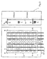
- FIG. 1 schematically represents a traditional occupancy sensor 2 to introduce into the upholstery of a car seat as well as a cut through the molded 4 intended to overmold the sensor 2 in said padding.
- the sensor it is for example a force sensor of the type as described in document US-A-4,314,227, the resistance of which electric varied according to the applied force.
- Sensor 2 presents several active zones 6, which are arranged on several strips 8 of substantially parallel leaves.
- the active zones 6 of a band 8 are at each time connected to each other by means of a ventilation channel 10 which opens on one side into a cutout 12 in the sensor.
- the cutouts 12 are arranged in such a way in the edge of the sensor, that after introduction of the sensor into the seat upholstery, they overlap with recesses in the padding used to receive reminders from lining 14, that is to say the elements for fixing the cover of the seat.
- the number and position of the cutouts 12 are therefore linked to the number and the position of the packing recalls 14 and thereby subject to stresses seat design and functionality. It is indeed clear that the dimensions of the recesses must be quite small and their number and position in the seat should be chosen so that the comfort of the seat is not diminished.
- FIG. 2 schematically represents an execution of a sensor occupancy 16 according to the present invention to introduce into the upholstery of a car seat and a cut through the mold 4 intended to overmold the sensor 16 in said padding.
- the sensor 2 of fig. 1 several active zones 6, which are arranged on several strips 8 of substantially parallel sheets. Multiple areas active 6 are connected to each other by a ventilation channel 10 which is extended so that after introduction of the sensor into the mold 4, a ventilation opening 18 of the ventilation channel 10 is arranged at outside the mold 4.
- a ventilation channel 10 which extends so substantially perpendicular to the strips 8.
- the grid thus created by the ventilation strips and channels give the sensor 16 a structure closed without cantilevered elements, which advantageously gives it a high stability against twisting of the bands 8 during foam injection in the mold 4.
- this structure facilitates the removal of the film protective of the spacer during the production of the sensor, thus allowing a automation of sensor manufacturing.
- the ventilation channels could also connect the active areas 6 arranged in a strip and therefore extend in the same direction as the bands.
- the active areas connected by the same channel ventilation can be shifted alternately, so that the channel of ventilation will have a sawtooth shape.
- the ventilation channels 10 opening to the outside of the mold 4 and not in recesses in the padding, the position of the sensor 16 in the body molded is independent of the number, position and shape of such recesses and can therefore be chosen according to functionality that are independent of other factors.
- the holding pads are arranged symmetrically to the axis longitudinal of the mold.
- the holding pads 20 are arranged irregularly with respect to the axis of the mold 4, so that a reversing the upper and lower sides of the sensor becomes impossible.
- ventilation channels 10 open to the outside of the body molded and preferably on the same side thereof, has a very important advantage for mass production. Indeed, this facilitates in particular the cutting of any tips which are used to seal the channels ventilation 10 during introduction into the molded body and thus prevent the penetration of the foam into the channels. Now this division can be do it automatically and by a single cut.
- the openings of ventilation 18 ventilation channels 10 are visible from outside the body mold. We can therefore easily check the proper functioning of the ventilation 10 from the outside, that is to say recognize and remove a shutter possible ventilation channel 10.
- the electrical components can also be introduced in a car seat by other methods well known to men of trades. We can for example introduce the electrical components between two prefabricated parts of a seat.
Landscapes
- Engineering & Computer Science (AREA)
- Mechanical Engineering (AREA)
- Chemical & Material Sciences (AREA)
- Composite Materials (AREA)
- Push-Button Switches (AREA)
- Air-Conditioning For Vehicles (AREA)
- Chair Legs, Seat Parts, And Backrests (AREA)
- Cooling Or The Like Of Electrical Apparatus (AREA)
- Casings For Electric Apparatus (AREA)
Claims (14)
- Verfahren zum Einbringen einer folienartigen elektrischen Komponente in einen Formkörper, wobei die elektrische Komponente (2) mindestens einen Ventilationskanal (10) umfasst, gekennzeichnet durch den Schritt der darin besteht, den Ventilationsskandal (10) derart in die Umfangsfläche oder in den unteren Bereich des Körpers münden zu lassen, dass der Raum zwischen zwei Folien der elektrischen Komponente (2) mit der Umgebung verbunden ist.
- Verfahren nach Anspruch 1, wobei die Einbringung der elektrischen Komponente (2) durch einen Einschäumprozess erfolgt, bei dem ein Schaum in eine Form (4) eingespritzt wird, dadurch gekennzeichnet, dass die elektrische Komponente (2) derart im Inneren der Form (4) angeordnet wird, dass der Ventilationskanal (10) der elektrischen Komponente (2) an eine Seitenwand oder an eine untere Wand der Form mündet.
- Verfahren nach Anspruch 2, dadurch gekennzeichnet, dass die elektrische Komponente (2) derart im Inneren der Form angeordnet wird, dass der Ventilationskanal (10) in den Außenbereich der Form (4) mündet.
- Verfahren nach einem der Ansprüche 2 oder 3, dadurch gekennzeichnet, dass die elektrische Komponente (2) vor dem Einspritzen des Schaums in die Form (4) mittels Halteklötzen (20) in der Form (4) positioniert wird.
- Verfahren nach Anspruch 4, dadurch gekennzeichnet, dass die Halteklötze (20) entnehmbar sind.
- Folienartige elektrische Komponente, die zum Einbringen in einen Formkörper bestimmt ist, umfassend mindestens einen Ventilationskanal (10), dadurch gekennzeichnet, dass der Ventilationskanal (10) derart ausgebildet ist, dass er beim Einbringen der elektrischen Komponente (2) in den Formkörper in die Umfangsfläche oder in den unteren Bereich des Formkörpers mündet, so dass ein Raum zwischen zwei Folien der elektrischen Komponente (2) mit der Umgebung verbunden ist.
- Elektrische Komponente nach Anspruch 6, dadurch gekennzeichnet dass der Ventilationskanal (10) derart ausgebildet ist, dass der Ventilationskanal (10) beim Umschäumen der elektrischen Komponente in einer Form (4) an eine Seitenwand oder an eine seitliche Wand der Form (4) mündet.
- Elektrische Komponente nach Anspruch 7, dadurch gekennzeichnet, dass der Ventilationskanal (10) derart ausgebildet ist, dass der Ventilationskanal (10) beim Umschäumen der elektrischen Komponente in einer Form (4) in den Außenbereich der Form (4) mündet.
- Elektrische Komponente nach einem der Ansprüche 6 bis 8, gekennzeichnet durch mehrere untereinander beanstandete aktive Bereiche (6), wobei jeder aktive Bereich (6) durch einen Ventilationskanal (10) mit dem Außenbereich des Formkörpers verbunden ist.
- Elektrische Komponente nach Anspruch 9, dadurch gekennzeichnet, dass ein Ventilationskanal (10) mehrere aktive Bereiche (6) mit dem Außenbereich verbindet.
- Elektrische Komponente nach einem der Ansprüche 9 bis 10, dadurch gekennzeichnet, dass die aktiven Bereiche (6) auf mehreren Streifen (8) angeordnet sind, die untereinander im wesentlichen parallel verlaufen, und dass die aktiven Bereiche (6), die im wesentlichen in einer Richtung quer zu den Streifen (8) ausgerichtet sind, untereinander mittels eines Ventilationskanals (10) verbunden sind, der sich im wesentlichen quer zu den Streifen erstreckt.
- Elektrische Komponente nach einem der Ansprüche sechs bis 11, dadurch gekennzeichnet, dass es sich um einen Drucksensor handelt, dessen elektrischer Widerstand sich in Abhängigkeit der angelegten Kraft verändert.
- Formkörpers mit einer folienartigen elektrischen Komponente, dadurch gekennzeichnet, dass die elektrische Komponente einen Ventilationskanal (10) umfasst, der in die Umgebungsfläche oder in den unteren Bereich des Formkörpers mündet.
- Fahrzeugsitz umfassend einen Formkörper nach dem vorhergehenden Anspruch.
Applications Claiming Priority (3)
| Application Number | Priority Date | Filing Date | Title |
|---|---|---|---|
| LU90063A LU90063B1 (fr) | 1997-05-14 | 1997-05-14 | Procéd pour introduire un composant électrique du type à feuilles dans un corps moulé |
| LU90063 | 1997-05-14 | ||
| PCT/EP1998/002677 WO1998051461A1 (fr) | 1997-05-14 | 1998-05-07 | Procede pour introduire un composant electrique du type a feuilles dans un corps moule |
Publications (2)
| Publication Number | Publication Date |
|---|---|
| EP1009604A1 EP1009604A1 (de) | 2000-06-21 |
| EP1009604B1 true EP1009604B1 (de) | 2002-07-24 |
Family
ID=19731684
Family Applications (1)
| Application Number | Title | Priority Date | Filing Date |
|---|---|---|---|
| EP98925549A Expired - Lifetime EP1009604B1 (de) | 1997-05-14 | 1998-05-07 | Verfahren zum einbringen einer folienartigen elektrischen komponente in einen formkörper |
Country Status (5)
| Country | Link |
|---|---|
| EP (1) | EP1009604B1 (de) |
| DE (1) | DE69806767T2 (de) |
| ES (1) | ES2181228T3 (de) |
| LU (1) | LU90063B1 (de) |
| WO (1) | WO1998051461A1 (de) |
Families Citing this family (1)
| Publication number | Priority date | Publication date | Assignee | Title |
|---|---|---|---|---|
| DE102006012072A1 (de) * | 2006-03-16 | 2007-09-20 | Olho-Technik Oleff & Holtmann Ohg | Verfahren zur Herstellung eines ummantelten, einbaufähigen elektrischen Funktionsteiles sowie elektrisches Funktionsteil |
Family Cites Families (3)
| Publication number | Priority date | Publication date | Assignee | Title |
|---|---|---|---|---|
| US4314227A (en) * | 1979-09-24 | 1982-02-02 | Eventoff Franklin Neal | Electronic pressure sensitive transducer apparatus |
| IE56790B1 (en) * | 1983-06-29 | 1991-12-18 | Motorola Inc | Electronic device method using a leadframe with an integral mold vent means |
| US5121289A (en) * | 1990-01-31 | 1992-06-09 | Honeywell Inc. | Encapsulatable sensor assembly |
-
1997
- 1997-05-14 LU LU90063A patent/LU90063B1/fr active
-
1998
- 1998-05-07 ES ES98925549T patent/ES2181228T3/es not_active Expired - Lifetime
- 1998-05-07 DE DE69806767T patent/DE69806767T2/de not_active Expired - Fee Related
- 1998-05-07 WO PCT/EP1998/002677 patent/WO1998051461A1/fr not_active Ceased
- 1998-05-07 EP EP98925549A patent/EP1009604B1/de not_active Expired - Lifetime
Also Published As
| Publication number | Publication date |
|---|---|
| EP1009604A1 (de) | 2000-06-21 |
| WO1998051461A1 (fr) | 1998-11-19 |
| LU90063B1 (fr) | 1998-11-16 |
| ES2181228T3 (es) | 2003-02-16 |
| DE69806767D1 (de) | 2002-08-29 |
| DE69806767T2 (de) | 2003-03-27 |
Similar Documents
| Publication | Publication Date | Title |
|---|---|---|
| FR2717132A1 (fr) | Agencement d'air-bag. | |
| FR2815901A1 (fr) | Element rembourre pour vehicule et son procede de fabrication | |
| EP0269470B1 (de) | Verfahren zur Herstellung eines Rahmens aus Verbundwerkstoff | |
| FR2975649A1 (fr) | Piece de panneau interieur avec couverture d'airbag | |
| EP3330124A1 (de) | Fahrzeugsitz und sitzelement, das mit einem belüftungssystem ausgestattet ist, das eine leitung umfasst | |
| FR3007347A1 (fr) | Procede pour mouler par injection un boitier de coussin de securite gonflable. | |
| CH631222A5 (fr) | Barriere de securite. | |
| EP1009604B1 (de) | Verfahren zum einbringen einer folienartigen elektrischen komponente in einen formkörper | |
| EP3766715A1 (de) | Verstärkungseinsatz, der mit durchgangslöchern versehen ist | |
| FR2868742A1 (fr) | Flasque pour structure rigide d'un siege de vehicule, siege de vehicule comprenant un tel flasque et procede de fabrication d'un tel flasque | |
| EP3575156B1 (de) | Deckel zum verschliessen einer wandöffnung | |
| FR3067436A1 (fr) | Joint a armature rigide et en elastomere | |
| FR2952593A1 (fr) | Procede de rigidification d'un corps de dossier de siege, en matiere plastique soufflee | |
| WO2001019650A1 (fr) | Dispositif d'aide au deploiement d'un coussin gonflable de vehicule automobile | |
| EP2921277B1 (de) | Verfahren zur Herstellung eines Fahrzeugpaneels, das dazu bestimmt ist, ein Airbag- Modul abzudecken | |
| FR2763543A1 (fr) | Tableau de bord en matiere plastique | |
| EP3753788B1 (de) | Innenschale einer mittelkonsole eines kraftfahrzeugs | |
| FR3102114A1 (fr) | Siège pour un véhicule automobile avec un dossier comprenant des bourrelets latéraux ajustables | |
| EP1967418B1 (de) | Struktur für die Innenpolsterung eines Kraftfahrzeugs und diese umfassende Elemente | |
| FR2998013A1 (fr) | Ensemble realise par collage et sertissage d’une doublure et d’une peau | |
| FR2931113A1 (fr) | Corps de dossier de siege rabattable pour vehicule | |
| EP3057766A1 (de) | Basis für ein zubehörteil und tankzubehörteil sowie verfahren zum herstellen eines tanks | |
| EP1413471A1 (de) | Ein Polsterelement mit einem Schaumkörper mit integrierter Detektionsmatte | |
| EP2183149B1 (de) | Auskleidung für den heckspoiler eines motorfahrzeugs sowie motorfahrzeug mit mindestens einer solchen auskleidung | |
| FR2945597A1 (fr) | Dispositif de retenue d'une coiffe sur la piece de rembourrage d'une structure par solidarisation avec cette structure. |
Legal Events
| Date | Code | Title | Description |
|---|---|---|---|
| PUAI | Public reference made under article 153(3) epc to a published international application that has entered the european phase |
Free format text: ORIGINAL CODE: 0009012 |
|
| 17P | Request for examination filed |
Effective date: 19990917 |
|
| AK | Designated contracting states |
Kind code of ref document: A1 Designated state(s): DE ES GB IT SE |
|
| GRAG | Despatch of communication of intention to grant |
Free format text: ORIGINAL CODE: EPIDOS AGRA |
|
| 17Q | First examination report despatched |
Effective date: 20011022 |
|
| GRAG | Despatch of communication of intention to grant |
Free format text: ORIGINAL CODE: EPIDOS AGRA |
|
| GRAH | Despatch of communication of intention to grant a patent |
Free format text: ORIGINAL CODE: EPIDOS IGRA |
|
| GRAH | Despatch of communication of intention to grant a patent |
Free format text: ORIGINAL CODE: EPIDOS IGRA |
|
| GRAA | (expected) grant |
Free format text: ORIGINAL CODE: 0009210 |
|
| AK | Designated contracting states |
Kind code of ref document: B1 Designated state(s): DE ES FR GB IT SE |
|
| REG | Reference to a national code |
Ref country code: GB Ref legal event code: FG4D Free format text: NOT ENGLISH |
|
| RBV | Designated contracting states (corrected) |
Designated state(s): DE ES FR GB IT SE |
|
| REF | Corresponds to: |
Ref document number: 69806767 Country of ref document: DE Date of ref document: 20020829 |
|
| GBT | Gb: translation of ep patent filed (gb section 77(6)(a)/1977) |
Effective date: 20020830 |
|
| RAP2 | Party data changed (patent owner data changed or rights of a patent transferred) |
Owner name: IEE INTERNATIONAL ELECTRONICS & ENGINEERING S. |
|
| REG | Reference to a national code |
Ref country code: ES Ref legal event code: FG2A Ref document number: 2181228 Country of ref document: ES Kind code of ref document: T3 |
|
| PLBE | No opposition filed within time limit |
Free format text: ORIGINAL CODE: 0009261 |
|
| STAA | Information on the status of an ep patent application or granted ep patent |
Free format text: STATUS: NO OPPOSITION FILED WITHIN TIME LIMIT |
|
| 26N | No opposition filed |
Effective date: 20030425 |
|
| PGFP | Annual fee paid to national office [announced via postgrant information from national office to epo] |
Ref country code: GB Payment date: 20050420 Year of fee payment: 8 |
|
| PGFP | Annual fee paid to national office [announced via postgrant information from national office to epo] |
Ref country code: SE Payment date: 20050519 Year of fee payment: 8 |
|
| PGFP | Annual fee paid to national office [announced via postgrant information from national office to epo] |
Ref country code: ES Payment date: 20050609 Year of fee payment: 8 |
|
| PG25 | Lapsed in a contracting state [announced via postgrant information from national office to epo] |
Ref country code: GB Free format text: LAPSE BECAUSE OF NON-PAYMENT OF DUE FEES Effective date: 20060507 |
|
| PG25 | Lapsed in a contracting state [announced via postgrant information from national office to epo] |
Ref country code: SE Free format text: LAPSE BECAUSE OF NON-PAYMENT OF DUE FEES Effective date: 20060508 Ref country code: ES Free format text: LAPSE BECAUSE OF NON-PAYMENT OF DUE FEES Effective date: 20060508 |
|
| PGFP | Annual fee paid to national office [announced via postgrant information from national office to epo] |
Ref country code: IT Payment date: 20060531 Year of fee payment: 9 |
|
| REG | Reference to a national code |
Ref country code: FR Ref legal event code: CJ |
|
| EUG | Se: european patent has lapsed | ||
| GBPC | Gb: european patent ceased through non-payment of renewal fee |
Effective date: 20060507 |
|
| PGFP | Annual fee paid to national office [announced via postgrant information from national office to epo] |
Ref country code: DE Payment date: 20070410 Year of fee payment: 10 |
|
| REG | Reference to a national code |
Ref country code: ES Ref legal event code: FD2A Effective date: 20060508 |
|
| PGFP | Annual fee paid to national office [announced via postgrant information from national office to epo] |
Ref country code: FR Payment date: 20070410 Year of fee payment: 10 |
|
| REG | Reference to a national code |
Ref country code: FR Ref legal event code: ST Effective date: 20090119 |
|
| PG25 | Lapsed in a contracting state [announced via postgrant information from national office to epo] |
Ref country code: FR Free format text: LAPSE BECAUSE OF NON-PAYMENT OF DUE FEES Effective date: 20080602 Ref country code: DE Free format text: LAPSE BECAUSE OF NON-PAYMENT OF DUE FEES Effective date: 20081202 |
|
| PG25 | Lapsed in a contracting state [announced via postgrant information from national office to epo] |
Ref country code: IT Free format text: LAPSE BECAUSE OF NON-PAYMENT OF DUE FEES Effective date: 20070507 |