EP1009942B1 - Actionneur lineaire et rotatif pour changement de vitesse - Google Patents
Actionneur lineaire et rotatif pour changement de vitesse Download PDFInfo
- Publication number
- EP1009942B1 EP1009942B1 EP98945176A EP98945176A EP1009942B1 EP 1009942 B1 EP1009942 B1 EP 1009942B1 EP 98945176 A EP98945176 A EP 98945176A EP 98945176 A EP98945176 A EP 98945176A EP 1009942 B1 EP1009942 B1 EP 1009942B1
- Authority
- EP
- European Patent Office
- Prior art keywords
- shift
- control element
- relation
- gate
- central axis
- Prior art date
- Legal status (The legal status is an assumption and is not a legal conclusion. Google has not performed a legal analysis and makes no representation as to the accuracy of the status listed.)
- Expired - Lifetime
Links
- 230000033001 locomotion Effects 0.000 claims description 25
- 230000005540 biological transmission Effects 0.000 claims description 6
- 230000000903 blocking effect Effects 0.000 claims 5
- 230000002093 peripheral effect Effects 0.000 claims 2
- 230000001419 dependent effect Effects 0.000 claims 1
- 238000010586 diagram Methods 0.000 description 3
- 238000000034 method Methods 0.000 description 2
- 230000008878 coupling Effects 0.000 description 1
- 238000010168 coupling process Methods 0.000 description 1
- 238000005859 coupling reaction Methods 0.000 description 1
- 238000006073 displacement reaction Methods 0.000 description 1
- 239000012530 fluid Substances 0.000 description 1
- 230000007935 neutral effect Effects 0.000 description 1
- 230000002441 reversible effect Effects 0.000 description 1
- 230000007704 transition Effects 0.000 description 1
Images


Classifications
-
- F—MECHANICAL ENGINEERING; LIGHTING; HEATING; WEAPONS; BLASTING
- F16—ENGINEERING ELEMENTS AND UNITS; GENERAL MEASURES FOR PRODUCING AND MAINTAINING EFFECTIVE FUNCTIONING OF MACHINES OR INSTALLATIONS; THERMAL INSULATION IN GENERAL
- F16H—GEARING
- F16H61/00—Control functions within control units of change-speed- or reversing-gearings for conveying rotary motion ; Control of exclusively fluid gearing, friction gearing, gearings with endless flexible members or other particular types of gearing
- F16H61/26—Generation or transmission of movements for final actuating mechanisms
- F16H61/28—Generation or transmission of movements for final actuating mechanisms with at least one movement of the final actuating mechanism being caused by a non-mechanical force, e.g. power-assisted
- F16H2061/2884—Screw-nut devices
-
- F—MECHANICAL ENGINEERING; LIGHTING; HEATING; WEAPONS; BLASTING
- F16—ENGINEERING ELEMENTS AND UNITS; GENERAL MEASURES FOR PRODUCING AND MAINTAINING EFFECTIVE FUNCTIONING OF MACHINES OR INSTALLATIONS; THERMAL INSULATION IN GENERAL
- F16H—GEARING
- F16H61/00—Control functions within control units of change-speed- or reversing-gearings for conveying rotary motion ; Control of exclusively fluid gearing, friction gearing, gearings with endless flexible members or other particular types of gearing
- F16H61/26—Generation or transmission of movements for final actuating mechanisms
- F16H61/28—Generation or transmission of movements for final actuating mechanisms with at least one movement of the final actuating mechanism being caused by a non-mechanical force, e.g. power-assisted
- F16H61/30—Hydraulic or pneumatic motors or related fluid control means therefor
-
- F—MECHANICAL ENGINEERING; LIGHTING; HEATING; WEAPONS; BLASTING
- F16—ENGINEERING ELEMENTS AND UNITS; GENERAL MEASURES FOR PRODUCING AND MAINTAINING EFFECTIVE FUNCTIONING OF MACHINES OR INSTALLATIONS; THERMAL INSULATION IN GENERAL
- F16H—GEARING
- F16H61/00—Control functions within control units of change-speed- or reversing-gearings for conveying rotary motion ; Control of exclusively fluid gearing, friction gearing, gearings with endless flexible members or other particular types of gearing
- F16H61/26—Generation or transmission of movements for final actuating mechanisms
- F16H61/28—Generation or transmission of movements for final actuating mechanisms with at least one movement of the final actuating mechanism being caused by a non-mechanical force, e.g. power-assisted
- F16H61/32—Electric motors , actuators or related electrical control means therefor
-
- Y—GENERAL TAGGING OF NEW TECHNOLOGICAL DEVELOPMENTS; GENERAL TAGGING OF CROSS-SECTIONAL TECHNOLOGIES SPANNING OVER SEVERAL SECTIONS OF THE IPC; TECHNICAL SUBJECTS COVERED BY FORMER USPC CROSS-REFERENCE ART COLLECTIONS [XRACs] AND DIGESTS
- Y10—TECHNICAL SUBJECTS COVERED BY FORMER USPC
- Y10T—TECHNICAL SUBJECTS COVERED BY FORMER US CLASSIFICATION
- Y10T74/00—Machine element or mechanism
- Y10T74/19—Gearing
- Y10T74/19219—Interchangeably locked
- Y10T74/19251—Control mechanism
-
- Y—GENERAL TAGGING OF NEW TECHNOLOGICAL DEVELOPMENTS; GENERAL TAGGING OF CROSS-SECTIONAL TECHNOLOGIES SPANNING OVER SEVERAL SECTIONS OF THE IPC; TECHNICAL SUBJECTS COVERED BY FORMER USPC CROSS-REFERENCE ART COLLECTIONS [XRACs] AND DIGESTS
- Y10—TECHNICAL SUBJECTS COVERED BY FORMER USPC
- Y10T—TECHNICAL SUBJECTS COVERED BY FORMER US CLASSIFICATION
- Y10T74/00—Machine element or mechanism
- Y10T74/20—Control lever and linkage systems
- Y10T74/20012—Multiple controlled elements
- Y10T74/20018—Transmission control
- Y10T74/2003—Electrical actuator
Definitions
- the invention relates to a switching device for a Gear change transmission in the preamble of Claim 1 explained Art.
- Such a switching device is the subject of the unpublished EP 0 828 099 A2.
- this switching device for a gear change transmission are a switching actuator, a selector actuator, a only axially displaceable relative to a housing arranged actuator, an auxiliary gear for converting a Rotary motion in a reciprocating motion, one with the Selector actuator connected brake and one on and disengageable locking device effectively arranged that two of the three actuators are fixed in relation to one another arranged and with the third actuator by the Auxiliary gear are connected and the selector actuator opposite the housing either rotatably or axially immovable is set.
- EP 0 828 099 A2 is essential in a switching device of the beginning mentioned type also skipping at least one intermediate gear when switching from one to allow current gear into a new gear, however are supposed to have special free travel for the switching actuator eliminated or largely avoided.
- the switching actuator remains in this switching device when it is operated in the associated with the new gear Angular position in the longitudinal directions of the central axis of the Housing immovably fixed by the locking device, so that special free travel for the switching actuator - around that Triggering of synchronization devices during this actuation avoid - are not necessary because those for dialing linear motion required for the new angle of rotation position only from the third, only axially displaceable with respect to the housing arranged actuator.
- this switching device there is a selector adjusting sleeve arranged concentrically to a control shaft and with the latter through the auxiliary gear in the form of a backdrop-link pin arrangement connected, the switching actuating shaft by a rod-shaped actuator with a pressure medium actuator the axial piston type is connected, while for Actuation of the brake working on the selector sleeve Electromagnet is used.
- the dial sleeve is opposite the housing immovable in the longitudinal directions of the central axis set while the shift actuator shaft in their one respective shift gate for shifting one or two gears assigned significant rotational angle positions by a Locking device is locked.
- DE 41 37 142 A1 is a switching device of a different type known in which an electric motor by a screw thread to convert a rotary motion into a reciprocating one Movement with a rotatable and axial in a housing slidably mounted shift rod is connected by an engaging and disengaging braking device compared to the Housing is fixable so that the shift rod in engaged state of the brake only axially displaceable - on the other hand when the brake is disengaged both axially displaceable and rotatable relative to the housing is arranged.
- the shift rod is counter-rotating Brake engaging and disengaging clutch directly with the motor shaft connected to the electric motor. When switching between dialing and Shifting must be reversed as well as clutch and brake the electric motor is stopped.
- Another switching device is known from DE 43 09 027 A1 known in another type, in which one versus one Pressure fluid cylinder rotatably and axially displaceably arranged Switching shaft through a first axial piston Printing medium cylinder directly in the directions of the Shift shaft axis for shifting the gears is shiftable.
- the Shift shaft is driven by a second axial piston Pressure cylinder with the mediation of an auxiliary gear to convert a back and forth movement into a Rotational movement with respect to the shift shaft axis Rotational movements to select the shift gates.
- the object underlying the invention is essentially to see therein a switching device mentioned at the beginning further educate that the process security of the Circuit sequence is improved.
- the stationary shifting gate in which a Link pin arranged fixed to the switching actuator , it ensures that switching between Shifting and dialing only in the internal structure of the transmission predetermined positions can be done. This will make the Process reliability of the circuit sequence improved.
- the internal gear shift can be simplified be by the locking elements for switching and Selection movement on the switching actuator can be omitted.
- Claims 2 to 4 and 8 to 10 have advantageous Refinements of the switching device according to the invention for Object.
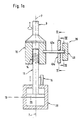
- a switching actuator 9 in the form of a Shaft
- a selector actuator 10 in the form of a hollow shaft or Sleeve
- a rod-shaped actuator 11 coaxial with a double-acting axial piston 29 arranged.
- the switching actuator 9 is opposite the selector actuator 10 designed to be immobile or in one piece.
- the selector actuator 10 is by an auxiliary gear 14 in the form of a screw gear to convert a back and forth movement into a Rotational movement with the only axially displaceable opposite the housing 8 arranged actuator 11 connected, which in turn with the axial piston 29 in a motion-proof connection stands.
- the switching actuator 9 is in a significant rotational angle position operable (Fig.3), in which an axial groove 21 on Outer circumference of the selector actuator 10 in a central axis 7-7 containing reference plane 30-30 of the housing 8 lies.
- the axial groove 21 is the shift gate 3-4 for optional shifting the forward gears 3 and 4 assigned so that by actuation of the switching actuator 9 in the significant rotational angle position in the directions of the central axis 7 - 7 of the Forward gear 3 or 4 is either engaged or disengaged.
- the switching actuator 9 is in a further significant rotational angle position can be actuated (FIG. 3), in which an axial groove 22 on the outer circumference of the selector actuator 10 in the reference plane 30 - 30 lies.
- the axial groove 22 is the shift gate 1-2 for optional shifting of forward gears 1 and 2 assigned so that by actuating the in the significant rotational angle position standing switching actuator 9 in the directions of Central axis 7 - 7 the forward gear 1 or 2 either one or is disengaged.
- the switching actuator 9 is in a third significant rotational angle position can be actuated (FIG. 3), in which an axial groove 23 on the outer circumference of the selector actuator 10 in the reference plane 30 - 30 lies.
- the axial groove 23 is the shift gate 5-6 optional shifting of forward gears 5 and 6 assigned so that by actuating the in the significant rotational angle position standing switching actuator 9 in the directions of Central axis 7 - 7 the forward gear 5 or 6 either one or is disengaged.
- the selector actuator 10 in the Directions of the central axis 7 - 7 by an engaging and disengaging Locking device 12 fixed relative to the housing 8, a locking engagement member 19 in a circumferential groove 20 is so indented on the outer circumference of the selector actuator 10 that the selector actuator 10 is only axially immovable is set.
- the axial piston 29 has a significant stroke position 16, in which the switching actuator 9 in the unactuated state Rest position centered by return springs at the transition between a predetermined shift gate and a neutral one Selector gate of the circuit diagram of a manual shift lever occupies. In the rest position is the switching actuator 9 in the significant angular position of the predetermined shift gate, wherein the brake engagement member 18 into the associated axial groove 21st intervenes.
- a stroke position 16 indicating Travel sensor 15 with a servomotor 17 of the brake 13 controlling, but not shown connected device.
- the linkage coupling between locking device 12, brake 13 and servomotor 17 is made so that the selector actuator 10 relative to the housing 8 either exclusively axially is immovable or arranged only in a rotationally fixed manner.
- a link pin 42 which is guided in a stationary shift link 43 and which is designed in accordance with the circuit diagram of a manual shift lever, is arranged in a manner fixed in terms of movement relative to the switching actuator 9 and radially to the central axis 7-7.
- the mode of operation of the switching device is explained below using a switching sequence.
- the shift actuator 9 In the case of an upshift from second gear to third gear, the shift actuator 9 initially assumes the rotational angle position in which the axial groove 22 assigned to the shift gate 1 - 2 lies in the reference plane 30 - 30 and receives the brake engagement member 18.
- the second gear By controlling the servomotor 28 in its significant stroke position 16, the second gear is disengaged and the shift actuator 9 is shifted into the selector gate in the direction of the central axis 7-7.
- the displacement sensor 15 reverses the servomotor 17 of the brake 13, so that the selector actuator 10 is fixed in relation to the housing 8 by the fixing device 12 in the longitudinal directions of the central axis 7-7.
- a link pin 42a Movable to the switching actuator 9 and radially to Central axis 7-7 is a link pin 42a, which in a stationary shifting gate 43a - which accordingly the circuit diagram of a manual shift lever is formed - guided and is forcibly coupled with an interchangeable gate 35.
- This Alternating lock gate 35 has one between two Rotational angle end positions 36, 37 reversible link plate 40 with a rectilinear slot slot 41 for the Setting pin 42a.
- the Link pin 42a In the angular position 36 the Link pin 42a such a position relative to the stationary Switching gate 43a that the dialing movements 45 of Setting pin 42a along a setting selection section locked and the switching movements 44 of the link pin 42a are released.
- the Link plate 40 In the angular position 37 of the Link plate 40 has the link slot 41 such Position opposite the shift gate 43a that the Switching movements 44 of the link pin 42a along a respective gate switching section locked and the Dialing movements 45 of the latter are released.
- the interchangeable gate 35 is or is in the Rotation angle end position 36 is actuated when the link pin 42a reaches the shift gate containing the gear to be shifted or is in the latter.
- the interchangeable gate 35 is or is in the Rotational angle end position 37 is actuated when the link pin 42a yourself in the backdrop selection section - but not in the area of the shifting alley to be shifted is located.
Landscapes
- Engineering & Computer Science (AREA)
- General Engineering & Computer Science (AREA)
- Mechanical Engineering (AREA)
- Gear-Shifting Mechanisms (AREA)
Claims (10)
- Dispositif de commande d'une boíte de vitesses à engrenages, comportantet dans lequel deux organes de positionnement parmi les trois (organe de positionnement de commande 9, organe de positionnement de sélection 10) sont à la fois agencés solidairement vis-à-vis du mouvement l'un par rapport à l'autre du moins dans les directions longitudinales de l'axe central (7-7) et reliés au troisième organe de positionnement (11) par la transmission auxiliaire (14),un organe de positionnement de commande (9) agencé mobile en rotation par rapport à un axe central (7-7) d'un carter (8) et mobile en translation axiale,un organe de positionnement de sélection (10) coaxial par rapport à l'axe central, qui est agencé mobile en rotation par rapport au carter (8),un organe de positionnement (11) coaxial par rapport à l'axe central (7-7), qui est agencé mobile exclusivement en translation axiale par rapport au carter,des moyens pour fixer l'organe de positionnement de sélection (10) par rapport au carter (8) dans les directions longitudinales de l'axe central (7-7),un frein (13) susceptible d'être engagé et dégagé pour fixer l'organe de positionnement de sélection (10) par rapport au carter (8) dans les directions périphériques de l'axe central (7-7),une transmission auxiliaire (14) pour convertir un mouvement en va-et-vient en un mouvement de rotation,
et dans lequel un dispositif d'arrêt (12) susceptible d'être engagé et dégagé est relié, en termes d'action, aussi bien à l'organe de positionnement de sélection (10) qu'au frein (13), de telle sorte que l'organe de positionnement de sélection (10) peut être fixé par rapport au carter (8) en alternance soit exclusivement dans les directions périphériques soit exclusivement dans les directions longitudinales de l'axe central (7-7),
et dans lequel l'organe de positionnement de sélection (10) est relié via la transmission auxiliaire (14) à l'organe de positionnement (11) agencé mobile exclusivement en translation axiale par rapport au carter (8),
caractérisé en ce qu'une tige de coulisse (42) est guidée dans une coulisse de changement de vitesses stationnaire (43) qui représente le schéma de changement de vitesses d'un levier de changement de vitesses manuel, et en ce que la tige de coulisse (42) est agencée de façon stationnaire par rapport à l'organe de positionnement de commande (9) ainsi que radialement par rapport à l'axe central (7-7). - Dispositif de commande selon la revendication 1, caractérisé en ce qu'un détecteur (15) est agencé pour détecter une position médiane significative (16) de l'organe de positionnement (11) agencé mobile exclusivement en translation axiale par rapport au carter (8) et coopère avec un servomoteur (17) pour actionner le frein (13), de telle sorte que le frein (13) est susceptible d'être engagé et dégagé exclusivement dans la position significative (16) de l'organe de positionnement (11).
- Dispositif de commande selon l'une ou l'autre des revendications 1 et 2, caractérisé en ce que l'organe de positionnement de sélection (10) comprend une gorge périphérique (20) centrée sur à l'axe central (7-7), dans laquelle peut venir s'engager un organe d'engagement d'arrêt (19) du dispositif d'arrêt (12), qui est agencé solidairement vis-à-vis du mouvement par rapport à un organe d'engagement (18), susceptible d'être engagé et dégagé, du frein (13).
- Dispositif de commande selon la revendication 3, caractérisé en ce que la gorge périphérique (20) est agencée, par rapport à l'axe central (7-7), diamétralement à l'opposé de gorges axiales (21 à 23) de l'organe de positionnement de sélection (10), dans lesquelles peut venir s'engager l'organe d'engagement de frein (18), et en ce que l'organe d'engagement de frein (18) et l'organe d'engagement d'arrêt (19) sont reliés par au moins une tringlerie (25 et/ou 26) en forme d'étrier entourant l'organe de positionnement de sélection (10).
- Dispositif de commande selon l'une des revendications 1 et 2, caractérisé en ce l'organe de positionnement de commande (9) est relié avec dépendance vis-à-vis du mouvement à une coulisse de blocage réversible (35) qui est réalisée sous forme de frein et de dispositif d'arrêt et qui est réversible entre deux positions finales (36, 37), et en ce que les mouvements de rotation (45) de l'organe de positionnement de commande (9) sont bloqués dans l'une des positions finales (36) de la coulisse de blocage réversible (35) et les mouvements en va-et-vient (44) de l'organe de positionnement de commande (9) sont bloqués dans l'autre position finale (37) par l'intermédiaire d'une tige de coulisse (42a) qui est reliée à l'organe de positionnement de commande (9) et qui s'engage dans la coulisse de blocage réversible (35).
- Dispositif de commande selon la revendication 5, caractérisé en ce que la coulisse de blocage réversible (35) comprend un disque de coulisse (40) qui peut être actionné entre deux positions angulaires finales (36, 37) décalées de 90° l'une de l'autre et qui comprend une fente de coulisse rectiligne (41) qui bloque les mouvements de sélection de l'organe de positionnement de commande (9) dans l'une des positions angulaires finales (36) et qui bloque les mouvements de commande dudit organe dans l'autre position angulaire finale (37).
- Dispositif de commande selon la revendication 6, caractérisé en ce que la tige de coulisse (42a) de la coulisse de commande stationnaire (43a) s'engage en supplément dans la fente (41) de la coulisse de blocage réversible (35).
- Dispositif de commande selon l'une des revendications 1 à 7, caractérisé en ce que la transmission auxiliaire (14) est formée par une transmission hélicoïdale.
- Dispositif de commande selon l'une des revendications 1 à 8, caractérisé en ce que l'organe de positionnement (11) agencé mobile exclusivement en translation axiale par rapport au carter (8) est relié à un servomoteur à fluide sous pression (28) du type à piston axial.
- Dispositif de commande selon l'une des revendications 1 à 9, caractérisé en ce que le servomoteur (17) est réalisé sous forme d'électroaimant pour l'immobilisation de l'organe de positionnement de sélection (10) par rapport au carter (8) dans les directions périphériques de l'axe central (7-7).
Applications Claiming Priority (3)
| Application Number | Priority Date | Filing Date | Title |
|---|---|---|---|
| DE1997137305 DE19737305C1 (de) | 1996-09-04 | 1997-08-27 | Schaltvorrichtung für ein Zahnräderwechselgetriebe |
| DE19737305 | 1997-08-27 | ||
| PCT/EP1998/005020 WO1999010665A2 (fr) | 1997-08-27 | 1998-08-07 | Dispositif de commande pour variateur de vitesse |
Publications (2)
| Publication Number | Publication Date |
|---|---|
| EP1009942A2 EP1009942A2 (fr) | 2000-06-21 |
| EP1009942B1 true EP1009942B1 (fr) | 2002-10-23 |
Family
ID=7840314
Family Applications (1)
| Application Number | Title | Priority Date | Filing Date |
|---|---|---|---|
| EP98945176A Expired - Lifetime EP1009942B1 (fr) | 1997-08-27 | 1998-08-07 | Actionneur lineaire et rotatif pour changement de vitesse |
Country Status (6)
| Country | Link |
|---|---|
| US (1) | US6334371B1 (fr) |
| EP (1) | EP1009942B1 (fr) |
| JP (1) | JP2001514367A (fr) |
| KR (1) | KR20010023379A (fr) |
| BR (1) | BR9812009A (fr) |
| WO (1) | WO1999010665A2 (fr) |
Families Citing this family (10)
| Publication number | Priority date | Publication date | Assignee | Title |
|---|---|---|---|---|
| US7219571B2 (en) * | 2004-11-15 | 2007-05-22 | Borgwarner, Inc. | Transmission having an electro-mechanical gear actuation system |
| US7845249B2 (en) * | 2006-09-08 | 2010-12-07 | Schaeffler Technologies Gmbh & Co. Kg | Single motor transmission shifting mechanism for a motor vehicle transmission |
| EP2163792B1 (fr) * | 2008-09-16 | 2012-10-31 | Valeo Sicherheitssysteme GmbH | Dispositif d'actionneur pour une transmission d'un véhicule automobile |
| US8376906B2 (en) * | 2008-12-09 | 2013-02-19 | Borgwarner Inc. | Automatic transmission for a hybrid vehicle |
| US8172715B2 (en) * | 2009-02-03 | 2012-05-08 | Ford Global Technologies, Llc | Multiplexed gear actuation system for a dual clutch transmission |
| EP2449290B1 (fr) | 2009-06-29 | 2015-10-21 | Borgwarner Inc. | Valve hydraulique destinée à être utilisée dans un module de transmission automatique |
| JP5472729B2 (ja) | 2010-02-24 | 2014-04-16 | 株式会社ジェイテクト | 変速装置 |
| JP5440861B2 (ja) | 2010-03-24 | 2014-03-12 | 株式会社ジェイテクト | 変速機駆動装置 |
| EP2711592B1 (fr) * | 2012-09-21 | 2015-05-27 | C.R.F. Società Consortile per Azioni | Dispositif pour la sélection et l'engagement des vitesses d'une boîte de vitesses pour véhicules à moteur |
| WO2018118129A1 (fr) * | 2016-12-22 | 2018-06-28 | Eaton Corporation | Transmission à haut rendement et à puissance élevée |
Family Cites Families (13)
| Publication number | Priority date | Publication date | Assignee | Title |
|---|---|---|---|---|
| US4297910A (en) * | 1979-09-17 | 1981-11-03 | Ford Motor Company | Transmission gear selector control |
| US5251503A (en) * | 1991-09-12 | 1993-10-12 | General Motors Corporation | Electro-mechanical power controller for a gear shift mechanism |
| US5357821A (en) * | 1993-04-13 | 1994-10-25 | General Motors Corporation | Transmission and shift control |
| DE19527893C1 (de) * | 1995-07-29 | 1996-10-31 | Ford Werke Ag | Elektrische Schaltvorrichtung für Wechselgetriebe von Kraftfahrzeugen |
| DE19610491A1 (de) * | 1996-03-18 | 1997-09-25 | Hydraulik Ring Gmbh | Stelleinrichtung zur Automatisierung von Handschaltgetrieben von Kraftfahrzeugen |
| DE19628642C2 (de) * | 1996-07-16 | 1998-09-10 | Ford Global Tech Inc | Elektromechanische Schaltvorrichtung für Wechselgetriebe von Kraftfahrzeugen |
| DE19635866C2 (de) * | 1996-09-04 | 1998-07-23 | Daimler Benz Ag | Schaltvorrichtung für ein Zahnräderwechselgetriebe |
| ES2153255B1 (es) * | 1996-09-23 | 2001-09-01 | Fichtel & Sachs Ag | "dispositivo de ajuste de un elemento de salida desplazable en dos clases de movimiento". |
| FR2764028B1 (fr) * | 1997-05-28 | 2001-11-09 | Mannesmann Sachs Ag | Dispositif de positionnement |
| DE19733621C1 (de) * | 1997-08-04 | 1999-04-08 | Mannesmann Sachs Ag | Stelleinrichtung zur automatisierten Betätigung eines Getriebes |
| DE19741633C1 (de) * | 1997-09-20 | 1999-03-25 | Ford Global Tech Inc | Schaltvorrichtung für ein Wechselgetriebe von Kraftfahrzeugen |
| JPH11270672A (ja) * | 1997-12-18 | 1999-10-05 | Aft Atlas Fahrzeugtechnik Gmbh | 操作装置 |
| JPH11201277A (ja) * | 1998-01-12 | 1999-07-27 | Aichi Mach Ind Co Ltd | 歯車式変速機の自動変速装置 |
-
1998
- 1998-08-07 EP EP98945176A patent/EP1009942B1/fr not_active Expired - Lifetime
- 1998-08-07 BR BR9812009-3A patent/BR9812009A/pt not_active Application Discontinuation
- 1998-08-07 JP JP2000507947A patent/JP2001514367A/ja active Pending
- 1998-08-07 KR KR1020007002019A patent/KR20010023379A/ko not_active Ceased
- 1998-08-07 US US09/486,263 patent/US6334371B1/en not_active Expired - Fee Related
- 1998-08-07 WO PCT/EP1998/005020 patent/WO1999010665A2/fr not_active Ceased
Also Published As
| Publication number | Publication date |
|---|---|
| US6334371B1 (en) | 2002-01-01 |
| BR9812009A (pt) | 2000-09-26 |
| EP1009942A2 (fr) | 2000-06-21 |
| WO1999010665A3 (fr) | 1999-06-17 |
| JP2001514367A (ja) | 2001-09-11 |
| WO1999010665A2 (fr) | 1999-03-04 |
| KR20010023379A (ko) | 2001-03-26 |
Similar Documents
| Publication | Publication Date | Title |
|---|---|---|
| DE19610104C2 (de) | Schaltvorrichtung für ein Zahnräderwechselgetriebe sowie Verfahren zum Steuern dafür | |
| EP0828099B1 (fr) | Dispositif de commande d'une boíte de vitesses | |
| DE19530616A1 (de) | Schaltvorrichtung für Zahnräderwechselgetriebe | |
| DE19628642C9 (de) | Elektromechanische Schaltvorrichtung für Wechselgetriebe von Kraftfahrzeugen | |
| DE69101801T2 (de) | Angetriebene Schalteinrichtung zum Schalten der Übersetzung eines Getriebes, insbesondere für Kraftfahrzeuge. | |
| EP2232107B1 (fr) | Dispositif de changement de vitesse pour boîtes de vitesses à plusieurs étages de véhicules automobiles | |
| EP0530466B1 (fr) | Changement de vitesse de boîte de vitesse | |
| DE69113224T2 (de) | Angetriebene Schalteinrichtung zum Schalten der Übersetzung eines Getriebes, insbesondere für Kraftfahrzeuge. | |
| DE69810030T2 (de) | Automatisierte Schaltvorrichtung für ein Gangwechselgetriebe | |
| EP0636819B1 (fr) | Mécanisme de sélection des vitesses d'un transmission | |
| WO1999010665A2 (fr) | Dispositif de commande pour variateur de vitesse | |
| EP1150048B1 (fr) | Dispositif de commande pour boíte de vitesses à engrenages | |
| WO2018055041A2 (fr) | Actionneur de rapport et de voie (xy) de boîte de vitesses | |
| EP0199731A1 (fr) | Dispositif de changement de vitesse. | |
| DE2655263C2 (de) | Schalteinrichtung für ein aus einem Haupt- und einem Zweibereichs- Gruppengetriebe bestehenden Zahnräderwechselgetriebe | |
| EP1291560B1 (fr) | Dispositif de changement de rapports à commande assistée | |
| DE19737305C1 (de) | Schaltvorrichtung für ein Zahnräderwechselgetriebe | |
| DE2621714B1 (de) | Schalteinrichtung fuer ein kraftfahrzeug-wechselgetriebe | |
| EP3830452B1 (fr) | Mécanisme de passage de vitesse pour une boîte de vitesses | |
| AT333602B (de) | Schalteinrichtung fur ein kraftfahrzeug-wechselgetriebe | |
| DE10033807C2 (de) | Schaltvorrichtung für ein Zahnräderwechselgetriebe | |
| DE10010040A1 (de) | Stufenwechselgetriebe | |
| DE4441967A1 (de) | Schaltvorrichtung für mehrgängiges Wechselgetriebe | |
| DE19748969C1 (de) | Schaltvorrichtung für Wechselgetriebe, insbesondere von Kraftfahrzeugen | |
| DE10259485A1 (de) | Getriebeschaltanordnung mit einer Schaltwalze zum gleichzeitigen Schalten von zwei Schaltmuffen |
Legal Events
| Date | Code | Title | Description |
|---|---|---|---|
| PUAI | Public reference made under article 153(3) epc to a published international application that has entered the european phase |
Free format text: ORIGINAL CODE: 0009012 |
|
| 17P | Request for examination filed |
Effective date: 19991204 |
|
| AK | Designated contracting states |
Kind code of ref document: A2 Designated state(s): DE ES FR GB IT SE Kind code of ref document: A2 Designated state(s): ES FR GB IT SE |
|
| 17Q | First examination report despatched |
Effective date: 20010522 |
|
| GRAG | Despatch of communication of intention to grant |
Free format text: ORIGINAL CODE: EPIDOS AGRA |
|
| RIC1 | Information provided on ipc code assigned before grant |
Free format text: 7F 16H 61/30 A, 7F 16H 63/20 B |
|
| RTI1 | Title (correction) |
Free format text: SHIFT ACTUATOR FOR A CHANGE SPEED GEAR |
|
| GRAG | Despatch of communication of intention to grant |
Free format text: ORIGINAL CODE: EPIDOS AGRA |
|
| GRAH | Despatch of communication of intention to grant a patent |
Free format text: ORIGINAL CODE: EPIDOS IGRA |
|
| GRAH | Despatch of communication of intention to grant a patent |
Free format text: ORIGINAL CODE: EPIDOS IGRA |
|
| RBV | Designated contracting states (corrected) |
Designated state(s): ES FR GB IT SE |
|
| REG | Reference to a national code |
Ref country code: DE Ref legal event code: 8566 |
|
| GRAA | (expected) grant |
Free format text: ORIGINAL CODE: 0009210 |
|
| AK | Designated contracting states |
Kind code of ref document: B1 Designated state(s): ES FR GB IT SE |
|
| PG25 | Lapsed in a contracting state [announced via postgrant information from national office to epo] |
Ref country code: GB Free format text: LAPSE BECAUSE OF FAILURE TO SUBMIT A TRANSLATION OF THE DESCRIPTION OR TO PAY THE FEE WITHIN THE PRESCRIBED TIME-LIMIT Effective date: 20021023 |
|
| REG | Reference to a national code |
Ref country code: GB Ref legal event code: FG4D Free format text: NOT ENGLISH |
|
| PG25 | Lapsed in a contracting state [announced via postgrant information from national office to epo] |
Ref country code: SE Free format text: LAPSE BECAUSE OF FAILURE TO SUBMIT A TRANSLATION OF THE DESCRIPTION OR TO PAY THE FEE WITHIN THE PRESCRIBED TIME-LIMIT Effective date: 20030123 |
|
| GBV | Gb: ep patent (uk) treated as always having been void in accordance with gb section 77(7)/1977 [no translation filed] |
Effective date: 20021023 |
|
| PG25 | Lapsed in a contracting state [announced via postgrant information from national office to epo] |
Ref country code: ES Free format text: LAPSE BECAUSE OF FAILURE TO SUBMIT A TRANSLATION OF THE DESCRIPTION OR TO PAY THE FEE WITHIN THE PRESCRIBED TIME-LIMIT Effective date: 20030429 |
|
| ET | Fr: translation filed | ||
| PLBE | No opposition filed within time limit |
Free format text: ORIGINAL CODE: 0009261 |
|
| STAA | Information on the status of an ep patent application or granted ep patent |
Free format text: STATUS: NO OPPOSITION FILED WITHIN TIME LIMIT |
|
| 26N | No opposition filed |
Effective date: 20030724 |
|
| PG25 | Lapsed in a contracting state [announced via postgrant information from national office to epo] |
Ref country code: FR Free format text: LAPSE BECAUSE OF NON-PAYMENT OF DUE FEES Effective date: 20040430 |
|
| REG | Reference to a national code |
Ref country code: FR Ref legal event code: ST |
|
| PG25 | Lapsed in a contracting state [announced via postgrant information from national office to epo] |
Ref country code: IT Free format text: LAPSE BECAUSE OF NON-PAYMENT OF DUE FEES Effective date: 20050807 |