EP1009961B1 - Systeme de conditionnement d'air a haute efficacite avec distribution d'un grand volume d'air - Google Patents
Systeme de conditionnement d'air a haute efficacite avec distribution d'un grand volume d'air Download PDFInfo
- Publication number
- EP1009961B1 EP1009961B1 EP98921242A EP98921242A EP1009961B1 EP 1009961 B1 EP1009961 B1 EP 1009961B1 EP 98921242 A EP98921242 A EP 98921242A EP 98921242 A EP98921242 A EP 98921242A EP 1009961 B1 EP1009961 B1 EP 1009961B1
- Authority
- EP
- European Patent Office
- Prior art keywords
- air
- stream
- space
- building
- cooled
- Prior art date
- Legal status (The legal status is an assumption and is not a legal conclusion. Google has not performed a legal analysis and makes no representation as to the accuracy of the status listed.)
- Expired - Lifetime
Links
- 238000004378 air conditioning Methods 0.000 title claims description 20
- 238000001816 cooling Methods 0.000 claims abstract description 35
- 238000000034 method Methods 0.000 claims abstract description 16
- 230000001143 conditioned effect Effects 0.000 claims abstract description 8
- 239000002274 desiccant Substances 0.000 claims description 3
- 238000007664 blowing Methods 0.000 claims 2
- 239000000463 material Substances 0.000 claims 1
- 238000007791 dehumidification Methods 0.000 abstract description 12
- 238000010438 heat treatment Methods 0.000 abstract description 12
- 230000003068 static effect Effects 0.000 abstract description 11
- 230000004048 modification Effects 0.000 abstract description 2
- 238000012986 modification Methods 0.000 abstract description 2
- 238000010276 construction Methods 0.000 abstract 1
- 239000003570 air Substances 0.000 description 96
- 238000009423 ventilation Methods 0.000 description 12
- 230000008901 benefit Effects 0.000 description 9
- XLYOFNOQVPJJNP-UHFFFAOYSA-N water Substances O XLYOFNOQVPJJNP-UHFFFAOYSA-N 0.000 description 9
- 238000013461 design Methods 0.000 description 4
- 238000011084 recovery Methods 0.000 description 4
- 238000013459 approach Methods 0.000 description 3
- 238000010586 diagram Methods 0.000 description 3
- 238000005265 energy consumption Methods 0.000 description 2
- 230000007613 environmental effect Effects 0.000 description 2
- 238000001704 evaporation Methods 0.000 description 2
- 230000008595 infiltration Effects 0.000 description 2
- 238000001764 infiltration Methods 0.000 description 2
- 230000007246 mechanism Effects 0.000 description 2
- 239000002184 metal Substances 0.000 description 2
- 238000012546 transfer Methods 0.000 description 2
- 241000233866 Fungi Species 0.000 description 1
- 238000009825 accumulation Methods 0.000 description 1
- 239000012080 ambient air Substances 0.000 description 1
- 238000009395 breeding Methods 0.000 description 1
- 230000001488 breeding effect Effects 0.000 description 1
- 239000012267 brine Substances 0.000 description 1
- 239000004566 building material Substances 0.000 description 1
- 230000005465 channeling Effects 0.000 description 1
- 238000007906 compression Methods 0.000 description 1
- 230000003750 conditioning effect Effects 0.000 description 1
- 230000005611 electricity Effects 0.000 description 1
- 239000011152 fibreglass Substances 0.000 description 1
- 230000036541 health Effects 0.000 description 1
- 230000020169 heat generation Effects 0.000 description 1
- 238000009413 insulation Methods 0.000 description 1
- 239000007788 liquid Substances 0.000 description 1
- 238000012423 maintenance Methods 0.000 description 1
- 239000000203 mixture Substances 0.000 description 1
- 238000005457 optimization Methods 0.000 description 1
- 230000009467 reduction Effects 0.000 description 1
- 239000003507 refrigerant Substances 0.000 description 1
- 238000005057 refrigeration Methods 0.000 description 1
- 230000000241 respiratory effect Effects 0.000 description 1
- 230000004044 response Effects 0.000 description 1
- HPALAKNZSZLMCH-UHFFFAOYSA-M sodium;chloride;hydrate Chemical compound O.[Na+].[Cl-] HPALAKNZSZLMCH-UHFFFAOYSA-M 0.000 description 1
- 239000000243 solution Substances 0.000 description 1
- 239000000126 substance Substances 0.000 description 1
Images
Classifications
-
- F—MECHANICAL ENGINEERING; LIGHTING; HEATING; WEAPONS; BLASTING
- F24—HEATING; RANGES; VENTILATING
- F24F—AIR-CONDITIONING; AIR-HUMIDIFICATION; VENTILATION; USE OF AIR CURRENTS FOR SCREENING
- F24F3/00—Air-conditioning systems in which conditioned primary air is supplied from one or more central stations to distributing units in the rooms or spaces where it may receive secondary treatment; Apparatus specially designed for such systems
- F24F3/12—Air-conditioning systems in which conditioned primary air is supplied from one or more central stations to distributing units in the rooms or spaces where it may receive secondary treatment; Apparatus specially designed for such systems characterised by the treatment of the air otherwise than by heating and cooling
- F24F3/14—Air-conditioning systems in which conditioned primary air is supplied from one or more central stations to distributing units in the rooms or spaces where it may receive secondary treatment; Apparatus specially designed for such systems characterised by the treatment of the air otherwise than by heating and cooling by humidification; by dehumidification
- F24F3/1411—Air-conditioning systems in which conditioned primary air is supplied from one or more central stations to distributing units in the rooms or spaces where it may receive secondary treatment; Apparatus specially designed for such systems characterised by the treatment of the air otherwise than by heating and cooling by humidification; by dehumidification by absorbing or adsorbing water, e.g. using an hygroscopic desiccant
- F24F3/1417—Air-conditioning systems in which conditioned primary air is supplied from one or more central stations to distributing units in the rooms or spaces where it may receive secondary treatment; Apparatus specially designed for such systems characterised by the treatment of the air otherwise than by heating and cooling by humidification; by dehumidification by absorbing or adsorbing water, e.g. using an hygroscopic desiccant with liquid hygroscopic desiccants
-
- F—MECHANICAL ENGINEERING; LIGHTING; HEATING; WEAPONS; BLASTING
- F24—HEATING; RANGES; VENTILATING
- F24F—AIR-CONDITIONING; AIR-HUMIDIFICATION; VENTILATION; USE OF AIR CURRENTS FOR SCREENING
- F24F1/00—Room units for air-conditioning, e.g. separate or self-contained units or units receiving primary air from a central station
- F24F1/0007—Indoor units, e.g. fan coil units
- F24F1/00075—Indoor units, e.g. fan coil units receiving air from a central station
-
- F—MECHANICAL ENGINEERING; LIGHTING; HEATING; WEAPONS; BLASTING
- F24—HEATING; RANGES; VENTILATING
- F24F—AIR-CONDITIONING; AIR-HUMIDIFICATION; VENTILATION; USE OF AIR CURRENTS FOR SCREENING
- F24F13/00—Details common to, or for air-conditioning, air-humidification, ventilation or use of air currents for screening
- F24F13/02—Ducting arrangements
- F24F13/06—Outlets for directing or distributing air into rooms or spaces, e.g. ceiling air diffuser
- F24F13/072—Outlets for directing or distributing air into rooms or spaces, e.g. ceiling air diffuser of elongated shape, e.g. between ceiling panels
-
- F—MECHANICAL ENGINEERING; LIGHTING; HEATING; WEAPONS; BLASTING
- F24—HEATING; RANGES; VENTILATING
- F24F—AIR-CONDITIONING; AIR-HUMIDIFICATION; VENTILATION; USE OF AIR CURRENTS FOR SCREENING
- F24F3/00—Air-conditioning systems in which conditioned primary air is supplied from one or more central stations to distributing units in the rooms or spaces where it may receive secondary treatment; Apparatus specially designed for such systems
-
- F—MECHANICAL ENGINEERING; LIGHTING; HEATING; WEAPONS; BLASTING
- F24—HEATING; RANGES; VENTILATING
- F24F—AIR-CONDITIONING; AIR-HUMIDIFICATION; VENTILATION; USE OF AIR CURRENTS FOR SCREENING
- F24F3/00—Air-conditioning systems in which conditioned primary air is supplied from one or more central stations to distributing units in the rooms or spaces where it may receive secondary treatment; Apparatus specially designed for such systems
- F24F3/12—Air-conditioning systems in which conditioned primary air is supplied from one or more central stations to distributing units in the rooms or spaces where it may receive secondary treatment; Apparatus specially designed for such systems characterised by the treatment of the air otherwise than by heating and cooling
- F24F3/14—Air-conditioning systems in which conditioned primary air is supplied from one or more central stations to distributing units in the rooms or spaces where it may receive secondary treatment; Apparatus specially designed for such systems characterised by the treatment of the air otherwise than by heating and cooling by humidification; by dehumidification
-
- F—MECHANICAL ENGINEERING; LIGHTING; HEATING; WEAPONS; BLASTING
- F24—HEATING; RANGES; VENTILATING
- F24F—AIR-CONDITIONING; AIR-HUMIDIFICATION; VENTILATION; USE OF AIR CURRENTS FOR SCREENING
- F24F3/00—Air-conditioning systems in which conditioned primary air is supplied from one or more central stations to distributing units in the rooms or spaces where it may receive secondary treatment; Apparatus specially designed for such systems
- F24F2003/003—Air-conditioning systems in which conditioned primary air is supplied from one or more central stations to distributing units in the rooms or spaces where it may receive secondary treatment; Apparatus specially designed for such systems with primary air treatment in the central station and subsequent secondary air treatment in air treatment units located in or near the rooms
-
- F—MECHANICAL ENGINEERING; LIGHTING; HEATING; WEAPONS; BLASTING
- F24—HEATING; RANGES; VENTILATING
- F24F—AIR-CONDITIONING; AIR-HUMIDIFICATION; VENTILATION; USE OF AIR CURRENTS FOR SCREENING
- F24F3/00—Air-conditioning systems in which conditioned primary air is supplied from one or more central stations to distributing units in the rooms or spaces where it may receive secondary treatment; Apparatus specially designed for such systems
- F24F3/12—Air-conditioning systems in which conditioned primary air is supplied from one or more central stations to distributing units in the rooms or spaces where it may receive secondary treatment; Apparatus specially designed for such systems characterised by the treatment of the air otherwise than by heating and cooling
- F24F3/14—Air-conditioning systems in which conditioned primary air is supplied from one or more central stations to distributing units in the rooms or spaces where it may receive secondary treatment; Apparatus specially designed for such systems characterised by the treatment of the air otherwise than by heating and cooling by humidification; by dehumidification
- F24F2003/144—Air-conditioning systems in which conditioned primary air is supplied from one or more central stations to distributing units in the rooms or spaces where it may receive secondary treatment; Apparatus specially designed for such systems characterised by the treatment of the air otherwise than by heating and cooling by humidification; by dehumidification by dehumidification only
-
- F—MECHANICAL ENGINEERING; LIGHTING; HEATING; WEAPONS; BLASTING
- F24—HEATING; RANGES; VENTILATING
- F24F—AIR-CONDITIONING; AIR-HUMIDIFICATION; VENTILATION; USE OF AIR CURRENTS FOR SCREENING
- F24F11/00—Control or safety arrangements
- F24F11/0001—Control or safety arrangements for ventilation
- F24F2011/0006—Control or safety arrangements for ventilation using low temperature external supply air to assist cooling
Definitions
- the present invention generally relates to ventilation systems for buildings, and more particularly relates to methods and systems for providing good quality conditioned air to occupied building spaces.
- Air-conditioning manufacturers, architects, and professional design engineers have expended huge efforts in optimizing the design of building air-conditioning and ventilation systems
- Annual sales of equipment amount to tens of billions of dollars and annual energy costs for heating and cooling have similar magnitudes.
- the costs associated with reduced productivity of workers because of uncomfortable environmental conditions may be several times these figures, although such consequential costs are difficult to quantify.
- Conventional approaches to air conditioning have inherent problems that severely limit their efficiency, raise installed cost, and frequently produce poor environmental comfort conditions in the building space. Solving these problems requires major changes in the basic configuration of air-conditioning systems.
- Conventional air-conditioning systems use a relatively small volume of air for cooling.
- the typical arrangement uses a vapor-compression refrigeration system to cool a mixture of return air and outside air to approximately 55° F and then distribute the cooled air through ducts to the building space.
- the low supply air temperatures are used because of the need to cool the air below its dew point to remove moisture.
- the low air temperatures are also necessary to meet the sensible cooling needs of the space without using excessively large ducts.
- the first relates to fan or blower energy consumption. Because air in the conventional systems flows through relatively restrictive ductwork, fan static pressures are quite high. Typical pressures range from less than 0.5 inches of water for residential systems to as much as 5 to 10 inches of water for large commercial cooling systems. These high static pressures result in large energy consumption by the fan, and also add to the cooling load for the rest of the system. In many commercial systems, the heat generated by fan operation accounts for as much as 20 to 30 percent of the total cooling load for the building. The net result is a very inefficient cooling system.
- a second problem pertains to the high compressor energy required.
- the required low air supply temperatures dictate even lower evaporating temperatures, typically 40° to 50° F for the compressor system. Such low evaporating temperatures necessitate increased work for the compressor which further reduces the efficiency of the system.
- a third problem with the conventional air conditioning system is poor indoor air quality associated with high duct humidity. Conditions over 70% relative humidity allow the growth of mold and fungus in ductwork. The relative humidity in the supply ducts for conventional systems is frequently over 90%. In addition, water from wet coils drips onto drain pans and can also wet nearby ductwork. These wet conditions create potential breeding grounds for many types of microbes that can cause health, respiratory, and odor problems.
- a fourth shortcoming with conventional systems is the high noise levels emitted.
- the high static pressure caused by restrictive ductwork creates a need for a powerful fan that usually is quite noisy.
- metal ducts are notorious noise transmitters.
- Common fixes for the noise problem include the use of fiberglass duct liners. Unfortunately these liners increase cost and pressure drop and also can contribute to problems with molds given the high relative humidity in most ducts.
- a fifth problem is the potential for drafts with conventional cooling systems.
- the low air supply temperatures and high velocities create the possibility of extremely uncomfortable conditions near the vents.
- Designers must take special care to ensure adequate mixing of room air and supply air to reduce drafts to acceptable levels.
- a sixth problem is the need for simultaneous heating and cooling.
- Most office buildings have a single air handling system for the interior and exterior zones. In cold weather the interior zones still need cooling because of heat from people, lights, equipment, etc., while the exterior zones need heat.
- the usual solution is to supply cool air to the entire building in order to satisfy the cooling needs of the interior, while perimeter heaters or local heaters in the ducts servicing the exterior zones provide the heat necessary to satisfy the heating load and overcome the cooling from the supply air.
- a major objective of the present invention is thus to improve energy efficiency and to reduce or eliminate the problems associated with existing conventional air conditioning systems discussed above.
- the present invention uses a fundamentally new and different approach to air conditioning.
- the invention involves the use of a large volumetric flow rate of air with a temperature that is close to that of the building space for space heating and cooling.
- a separate dehumidification system is used in humid climates.
- a ceiling plenum is used for the supply air and air returns throughout the building space.
- supply air enters the space through a vent near the ceiling along one wall and returns near the floor along the same wall. Pressure drops are kept very low because of the low air velocities. The low pressure and small temperature difference between the supply air and the room air allow for very low energy use and improved comfort.
- a method for providing conditioned air to the interior space of a building comprising the steps of: obtaining a stream of air from said space; cooling said stream of air to a temperature that is within about 8,33°C (15°F) of the temperature of the air in said space, without removing moisture from said stream of air; supplying the resulting cooled air to said space; and supplying a separate source of dehumidified air to said space .
- an air conditioning system for providing conditioned air to the interior space of a building, comprising: means for drawing a stream of air from said space, and for cooling said stream of air to a temperature that is above the dew point and within about 8,33°C (15°F) of the temperature of said air in said space, such that no moisture is removed from said stream of air, thereby producing a cooled stream of air; means for supplying said cooled stream of air to said space; and means for drawing a stream of outside air external to said building, and for dehumidifying said stream of outside air, and for supplying the stream of dehumidified outside air to said space.
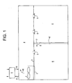
- Fig. 1 shows a first preferred embodiment of an air conditioning system according to the invention.
- Fan 1 draws intake air across coil 2, where it is cooled or heated.
- Ceiling 3 defines the bottom of a ceiling plenum 4 that serves as a flow path for air 40 leaving the fan 1.
- plenum 4 may extend over the entire area of interior building space 6.
- Coil 2 is located in or above ceiling 3, such that air from interior building space 6 is drawn across coil 2 and into plenum 4 by the fan 1.
- a number of vents 5 in ceiling 3 provide openings into the building space 6.
- Vent 7 in interior wall 42 provides an opening to allow air 8 to return to the coil through the building space.
- a separate external ventilation system 9 provides dehumidified outside air 10 to the building space through the plenum 4, and recovers energy from exhaust air 11.
- the fan 1 may be a propeller type, centrifugal fan, or other equivalent fan appropriate for moving large volumes of air.
- the fan 1 provides only a small static pressure, typically less than 0.2 inches of water.
- the low static pressures favor the use of low-speed fans, which result in a reduction of fan sound levels and fan energy usage in comparison with existing conventional systems.
- the coil 2 can contain water, brine or a liquid refrigerant made of substances well known in the art.
- the temperature of the cool supply air for cooling the space 6 through vents 5 normally would be greater than 65° F, and preferably about 70° F. Such higher temperatures prevent unwanted heat transfer through the ceiling 3 and help to keep the relative humidity in the plenum 4 below 70%.
- the coil temperature should be a least a few degrees above the dewpoint of the return air and preferably as close as practical to that of the supply air temperature. The high coil temperatures minimize the compressor energy required for cooling and eliminate problems associated with wet coils.
- the ceiling 3 normally would be a suspended ceiling, as generally known.
- the ceiling tiles should be sufficiently rigid to withstand the air pressure within the plenum 4, which would normally be less than 0.1 inches of water.
- the low static pressures in the plenum reduce the load on the tiles and reduce problems associated with air leakage around the edges of the tiles.
- the tiles should provide sufficient resistance to leakage and heat conduction to prevent undesirable heat transfer between the plenum 4 and the space 6. In many cases, existing suspended ceilings would meet these requirements without any significant modification.
- Vents 5 are designed to handle a large volume of air with a minimal pressure drop, typically only a few hundredths of an inch of water. Adjustment of the vents 5 may be manual or automatic. The vents are configured to introduce sufficient mixing so as to prevent undesirable drafts.
- air may be returned to the coil through the space under the floor.
- Vents 7 also may be provided with a control mechanism that is responsive to interior space temperature without the need for a separate power source.
- wax actuators and shape-memory actuators are capable of producing significant amounts of motion in response to relatively small changes in space temperature and could be used to control air flow through the vents.
- Co-pending U.S. provisional application serial number 60/077008 describes a roller damper mechanism that can work with these types of actuators.
- the dehumidified outside ventilation air 10 enters the building space through the ceiling plenum
- the exact location where the ventilation air is sent into the building space is somewhat arbitrary, so long as the temperature of the ventilation air is close to the temperature of the ambient air in the building space.
- the exhaust air 11 may be drawn from any location in the building and normally at least a portion would come from toilet exhaust.
- the ventilation/dehumidification system should incorporate an enthalpy wheel or other heat recovery device as generally known in the art, and preferably would be a desiccant-based system capable of providing low dewpoints.
- the temperature of the ventilation air should be close to the temperature of the air in the building space, although this would not be required if the ventilation air is mixed into the supply air.
- the ventilation system should also provide a small positive pressure for the building space to reduce possible of infiltration of outside air.
- the dehumidification system can simply further cool a portion of the air 40 leaving the cooling coil 2 so that temperature of the air 40 drops below the dewpoint.
- a heat pipe or other device for exchanging heat between the air on the coil and the air leaving the coil can increase the amount of moisture removed compared to sensible cooling, which further reduces energy usage.
- Such an arrangement is acceptable in cases where adequate outside air is available to the building space from infiltration or other sources.
- Numerous other dehumidification systems generally known in the prior art also could be used in the system of the present invention.
- the ASHRAE Handbooks describe many of these dehumidification options.
- the system of the present invention also has a major advantage in handling latent load.
- the use of an enthalpy wheel or other suitable heat exchanger can reduce loads associated with bringing in outside air by 80%. Heat recovery also greatly reduces heating requirements. For most office and retail buildings, the outside air is the main source of moisture.
- Use of a gas-driven desiccant system provides the opportunity to greatly reduce electricity demand charges while efficiently handling the ventilation load. Electrically driven systems are also an option.
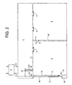
- Fig. 2 shows a variation of the first embodiment.
- the system of Fig. 2 is designed to greatly reduce the need for heating.
- a large volume of air is moved from the interior toward the exterior of the building, and return air is drawn from the building envelope.
- return air 13 is drawn from space 6 upward through channel 19 formed between the exterior glazing 12 and the interior glazing 17 of a window 44.
- This arrangement effectively eliminates any cold air resulting from heat loss through exterior glazing 12 and exterior wall 18.
- the return air then moves into channel 14, and through coil 16 as drawn by fan 15, and the conditioned air is discharged into the ceiling plenum 4 where it is distributed into the building space 6 through vents 5.
- the first advantage is that cold air is removed from the building envelope before it enters the conditioned space, by channeling return air adjacent to the exterior of the building.
- the second advantage is that this air is then routed toward the interior space to provide necessary cooling.
- the air returning from interior zones is used as a source of warm air for the exterior zones.
- This system does not require any significant amount of heat so long as the interior heat generation exceeds the exterior heating load.
- Proper insulation of windows and walls can effectively eliminate the need for heat in most larger buildings even in the most severe climates. The only time that heat would be required would be if the building were unoccupied for a long period of time with limited sunlight. Under these circumstances, the coils would provide heat to warm the entire building.
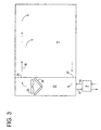
- Fig. 3 shows a third preferred embodiment of the invention. This configuration is suitable in retail space or similar locations with large open areas and few obstructions near the ceiling.
- fan 23 moves supply air 20 from coil 24 through vent 25 and into building space 6. The air returns through register 21 and return duct 22, back to coil 24.
- a separate dehumidification system 9 supplies outside air and recovers heat from exhaust air.
Landscapes
- Engineering & Computer Science (AREA)
- Chemical & Material Sciences (AREA)
- Combustion & Propulsion (AREA)
- Mechanical Engineering (AREA)
- General Engineering & Computer Science (AREA)
- Central Air Conditioning (AREA)
- Duct Arrangements (AREA)
- Ventilation (AREA)
- Sorption Type Refrigeration Machines (AREA)
Claims (18)
- Procédé pour fournir de l'air conditionné à l'espace intérieur (6) d'un immeuble comprenant les étapes suivantes :acquérir un flux d'air à partir dudit espace (6) ;refroidir le flux d'air à une température qui est à environ -9,44°C (15°F) de la température de l'air dans ledit espace (6), sans enlever l'humidité du flux d'air ;fournir l'air refroidi résultant audit espace (6) et ;fournir une source séparée d'air déshumidifié audit espace (6).
- Procédé selon la revendication 1, dans lequel la température du flux d'air refroidi est à environ -12,2°C (10°F) de la température de l'air dans l'espace de l'immeuble.
- Procédé selon la revendication 1, dans lequel l'humidité relative du flux d'air après refroidissement n'est pas supérieure à environ 90 %.
- Procédé selon la revendication 1, dans lequel l'humidité relative du flux d'air après refroidissement n'est pas supérieure à environ 70 %.
- Procédé selon la revendication 1, dans lequel l'étape de fourniture d'air refroidi comprend les étapes suivantes :souffler le flux d'air dans un vide de plafond (4) disposé entre un plafond (3) de l'immeuble et un plafond suspendu sous le plafond (3) de l'immeuble ; etrépartir l'air refroidi dans ledit espace (6) par une pluralité d'évents dans le plafond suspendu.
- Procédé selon la revendication 1, dans lequel l'étape de fourniture d'air refroidi comprend :souffler l'air refroidi dans une direction sensiblement horizontale à faible vitesse dans un espace séparé au-dessus de l'espace intérieur (6).
- Procédé selon la revendication 1, dans lequel l'étape de fourniture d'un flux d'air à partir dudit espace (6) comprend l'étape d'extraction du flux d'air à partir de la pièce par un canal d'écoulement allongé (14) prévu près d'une surface extérieure de l'immeuble.
- Procédé selon la revendication 1, dans lequel l'étape de fourniture d'air déshumidifié audit espace (6) comprend en outre les étapes suivantes :a) récupérer une partie séparée du flux d'air refroidi ;b) refroidir encore la partie séparée du flux d'air refroidi en dessous du point de rosée pour en supprimer l'humidité ; etc) renvoyer l'air déshumidifié au reste du flux d'air refroidi.
- Procédé selon la revendication 1, dans lequel l'étape de fourniture d'air déshumidifié audit espace (6) comprend les étapes suivantes :a) extraire un air refroidi extérieur (10) externe à l'immeuble ;b) enlever l'humidité de l'air refroidi extérieur (10) pour obtenir un flux d'air déshumidifié ;c) fournir l'air déshumidifié à l'espace (6) ; etd) extraire de l'air (11) dudit espace correspondant au volume d'air déshumidifié fourni dans ledit espace.
- Procédé selon la revendication 9, comprenant en outre l'étape consistant à échanger de l'énergie thermique et de l'humidité entre l'air d'évacuation (11) en provenance de l'espace (6) et le flux d'air extérieur incident (10).
- Procédé selon la revendication 9, dans lequel l'étape d'enlèvement d'humidité du flux d'air extérieur (10) comprend l'étape de refroidissement du flux d'air extérieur (10) à une température inférieure à la température de point de rosée extérieure.
- Procédé selon la revendication 9, dans lequel l'étape d'enlèvement d'humidité du flux d'air extérieur (10) comprend l'étape consistant à mettre en contact le flux d'air extérieur (10) avec un matériau de déssication.
- Procédé selon la revendication 7, dans lequel le canal d'écoulement (14) comprend un trajet d'écoulement dans une fenêtre (44) entre une vitre extérieure (12) et une vitre intérieure (17) de la fenêtre (44).
- Système de conditionnement d'air pour fournir de l'air conditionné à l'espace intérieur (6) d'un immeuble comprenant :des moyens pour extraire un flux d'air dudit espace (6) et pour refroidir le flux d'air à une température qui est au-dessus du point de rosée et à environ -9,44°C (15°F) de la température de l'air dans ledit espace (6), de sorte qu'aucune humidité n'est enlevée du flux d'air, produisant ainsi un flux d'air refroidi ;des moyens de fourniture du flux d'air refroidi audit espace (6) ; etdes moyens pour extraire un flux d'air extérieur (10) externe à l'immeuble, et pour déshumidifier le flux d'air extérieur (10) et pour fournir le flux d'air extérieur déshumidifié audit espace (6).
- Système de conditionnement d'air selon la revendication 14, dans lequel le flux d'air en provenance dudit espace (6) est refroidi à une température dans la plage d'environ - 12,2°C (10°F) à environ -9,44°C (15°F) de la température de l'air dans ledit espace (6).
- Système de conditionnement d'air selon la revendication 14, dans lequel les moyens de fourniture comprennent un vide (4) disposé entre un premier plafond (3) dudit espace (6) et un plafond suspendu sous le premier plafond (3).
- Système de conditionnement d'air selon la revendication 15, comprenant en outre une pluralité d'évents dans le plafond suspendu qui introduisent le flux d'air refroidi dans ledit espace (6) dans une direction horizontale.
- Système de conditionnement d'air selon la revendication 14, dans lequel les moyens pour extraire et pour déshumidifier l'air comprennent en outre des moyens pour extraire un flux d'air d'évacuation dudit espace (6).
Priority Applications (1)
| Application Number | Priority Date | Filing Date | Title |
|---|---|---|---|
| DK98921242T DK1009961T3 (da) | 1997-05-16 | 1998-05-15 | Höjeffektivt luftkonditioneringssystem med storvolumen luftfordeling |
Applications Claiming Priority (3)
| Application Number | Priority Date | Filing Date | Title |
|---|---|---|---|
| US4667697P | 1997-05-16 | 1997-05-16 | |
| US46676P | 1997-05-16 | ||
| PCT/US1998/010037 WO1998051978A2 (fr) | 1997-05-16 | 1998-05-15 | Systeme de conditionnement d'air a haute efficacite avec distribution d'un grand volume d'air |
Publications (3)
| Publication Number | Publication Date |
|---|---|
| EP1009961A2 EP1009961A2 (fr) | 2000-06-21 |
| EP1009961A4 EP1009961A4 (fr) | 2001-09-12 |
| EP1009961B1 true EP1009961B1 (fr) | 2005-03-16 |
Family
ID=21944769
Family Applications (1)
| Application Number | Title | Priority Date | Filing Date |
|---|---|---|---|
| EP98921242A Expired - Lifetime EP1009961B1 (fr) | 1997-05-16 | 1998-05-15 | Systeme de conditionnement d'air a haute efficacite avec distribution d'un grand volume d'air |
Country Status (11)
| Country | Link |
|---|---|
| US (1) | US6185943B1 (fr) |
| EP (1) | EP1009961B1 (fr) |
| CN (1) | CN1175228C (fr) |
| AT (1) | ATE291208T1 (fr) |
| AU (1) | AU730254C (fr) |
| BR (1) | BR9809832A (fr) |
| CA (1) | CA2288050C (fr) |
| DE (1) | DE69829387T2 (fr) |
| ES (1) | ES2239391T3 (fr) |
| PT (1) | PT1009961E (fr) |
| WO (1) | WO1998051978A2 (fr) |
Families Citing this family (19)
| Publication number | Priority date | Publication date | Assignee | Title |
|---|---|---|---|---|
| US6405543B2 (en) * | 1997-05-16 | 2002-06-18 | Work Smart Energy Enterprises Inc. | High-efficiency air-conditioning system with high-volume air distribution |
| KR100311601B1 (ko) * | 1999-06-29 | 2001-11-02 | 심상권 | 저장고 내부 제습 방법 및 그 제습 시스템 |
| US6434969B1 (en) * | 2000-10-13 | 2002-08-20 | Leon Sosnowski | Positive pressure heat pump system and method |
| US6494681B2 (en) | 2000-12-29 | 2002-12-17 | General Electric Company | Combined axial flow and centrifugal fan in an electrical motor |
| US6789618B2 (en) | 2001-09-05 | 2004-09-14 | Frederick J. Pearson | Energy recycling air handling system |
| US6986708B2 (en) * | 2002-05-17 | 2006-01-17 | Airfixture L.L.C. | Method and apparatus for delivering conditioned air using dual plenums |
| US20070066213A1 (en) * | 2002-05-17 | 2007-03-22 | Andrew Helgeson | Variable air volume time modulated floor terminal |
| US6945866B2 (en) | 2002-05-17 | 2005-09-20 | Airfixture L.L.C. | Method and apparatus for delivering conditioned air using pulse modulation |
| FR2877075B1 (fr) * | 2004-10-21 | 2013-01-04 | Ruhlemann Marie Jeanne | Dispositif de climatisation d'un local, et procede de climatisation d'un local. |
| US9314742B2 (en) | 2010-03-31 | 2016-04-19 | Toyota Motor Engineering & Manufacturing North America, Inc. | Method and system for reverse osmosis predictive maintenance using normalization data |
| US8221628B2 (en) | 2010-04-08 | 2012-07-17 | Toyota Motor Engineering & Manufacturing North America, Inc. | Method and system to recover waste heat to preheat feed water for a reverse osmosis unit |
| US8505324B2 (en) | 2010-10-25 | 2013-08-13 | Toyota Motor Engineering & Manufacturing North America, Inc. | Independent free cooling system |
| DK177247B1 (da) * | 2011-03-21 | 2012-08-06 | Js Ventilation As | Installationsløst teknikloft med integreret indblæsningsarmatur til luftkonditionering af indeklima i bygninger |
| DK177703B1 (da) | 2011-03-21 | 2014-03-24 | Js Ventilation As | Et luftindblæsningsarmatur, samt et loftsystem med luftindblæsningsarmaturet |
| DE102017112109A1 (de) * | 2017-06-01 | 2018-12-06 | Vogt Kälte-Klima Geräte- und Anlagenbau GmbH | Verfahren und Vorrichtung zur Raum-Temperierung |
| US20190107296A1 (en) | 2017-10-10 | 2019-04-11 | Trane International Inc. | Modular heat pump system |
| US20190299152A1 (en) * | 2018-03-27 | 2019-10-03 | GM Global Technology Operations LLC | Drying assembly with shape memory alloy actuator |
| US11801786B2 (en) * | 2021-03-01 | 2023-10-31 | Jag Mobile Solutions, Inc. | Mobile bunkhouse trailer |
| CA3145720A1 (fr) | 2022-01-14 | 2022-03-28 | Hybrid Energies Alternative Technologies Inc. | Systeme de thermopompe integre |
Family Cites Families (23)
| Publication number | Priority date | Publication date | Assignee | Title |
|---|---|---|---|---|
| US2793508A (en) * | 1953-12-07 | 1957-05-28 | Moritz L Mueller | Household air conditioning systems |
| US3122201A (en) * | 1960-05-05 | 1964-02-25 | Carrier Corp | Air conditioning system |
| US3823870A (en) * | 1970-07-14 | 1974-07-16 | Kilpatrick & Co | Air conditioning with mixing duct |
| US4258615A (en) * | 1978-08-31 | 1981-03-31 | Constantine Vivian | Ceiling construction for a heating, ventilation and air conditioning system |
| US4252003A (en) * | 1979-07-27 | 1981-02-24 | General Electric Company | Reduced power consumption air conditioning |
| US4244193A (en) * | 1979-08-24 | 1981-01-13 | Haakenson Marlan H | Ambient air cooling system |
| US4497182A (en) * | 1982-09-27 | 1985-02-05 | Benson Engineering & Mfg., Inc. | Dehumidifier |
| US4719761A (en) * | 1986-05-30 | 1988-01-19 | Cromer Charles J | Cooling system |
| US4683942A (en) * | 1986-09-29 | 1987-08-04 | American Standard Inc. | Assembly for retrofitting two air handling units to an installation originally meant for a single unit |
| US4769053A (en) * | 1987-03-26 | 1988-09-06 | Semco Mfg., Inc. | High efficiency sensible and latent heat exchange media with selected transfer for a total energy recovery wheel |
| US5119608A (en) * | 1990-04-26 | 1992-06-09 | Lauren Manufacturing Company | Convection gas flow inhibitor |
| US5065585A (en) * | 1990-10-25 | 1991-11-19 | Beutler Heating And Air Conditioning, Inc. | System for cooling the interior of a building |
| DE69214796T2 (de) * | 1991-08-20 | 1997-05-28 | Koester Helmut | Kühlanlage |
| EP0532874B1 (fr) * | 1991-09-14 | 1996-04-24 | HumanAir Patentverwertungsgesellschaft mbH | Conditionneur d'air pour le domaine humain |
| US5179998A (en) * | 1992-01-24 | 1993-01-19 | Champs Nicholas H Des | Heat recovery ventilating dehumidifier |
| US5265442A (en) * | 1992-05-12 | 1993-11-30 | Lamie Thomas T | Non-compressive auxiliary air conditioning system |
| US5325676A (en) * | 1992-08-24 | 1994-07-05 | Milton Meckler | Desiccant assisted multi-use air pre-conditioner unit with system heat recovery capability |
| US5685122A (en) * | 1995-05-11 | 1997-11-11 | Automated Air Structures, Inc. | Method and apparatus for maintaining an air-supported structure |
| CH691405A5 (de) * | 1995-11-03 | 2001-07-13 | Barcol Air | Verfahren und Vorrichtung zur Kühlung eines Raumes. |
| JP3327082B2 (ja) * | 1995-12-06 | 2002-09-24 | 松下電器産業株式会社 | 一体型空気調和機 |
| US5660048A (en) * | 1996-02-16 | 1997-08-26 | Laroche Industries, Inc. | Air conditioning system for cooling warm moisture-laden air |
| US5911747A (en) * | 1997-09-19 | 1999-06-15 | Pentech Energy Solutions, Inc. | HVAC system control incorporating humidity and carbon monoxide measurement |
| US6021644A (en) * | 1998-08-18 | 2000-02-08 | Ares; Roland | Frosting heat-pump dehumidifier with improved defrost |
-
1998
- 1998-05-15 AT AT98921242T patent/ATE291208T1/de not_active IP Right Cessation
- 1998-05-15 ES ES98921242T patent/ES2239391T3/es not_active Expired - Lifetime
- 1998-05-15 US US09/331,758 patent/US6185943B1/en not_active Expired - Fee Related
- 1998-05-15 PT PT98921242T patent/PT1009961E/pt unknown
- 1998-05-15 AU AU73898/98A patent/AU730254C/en not_active Ceased
- 1998-05-15 WO PCT/US1998/010037 patent/WO1998051978A2/fr not_active Ceased
- 1998-05-15 DE DE69829387T patent/DE69829387T2/de not_active Expired - Fee Related
- 1998-05-15 CA CA002288050A patent/CA2288050C/fr not_active Expired - Fee Related
- 1998-05-15 BR BR9809832-2A patent/BR9809832A/pt not_active IP Right Cessation
- 1998-05-15 EP EP98921242A patent/EP1009961B1/fr not_active Expired - Lifetime
- 1998-05-15 CN CNB988048264A patent/CN1175228C/zh not_active Expired - Fee Related
Also Published As
| Publication number | Publication date |
|---|---|
| CN1175228C (zh) | 2004-11-10 |
| US6185943B1 (en) | 2001-02-13 |
| DE69829387T2 (de) | 2006-04-13 |
| ATE291208T1 (de) | 2005-04-15 |
| EP1009961A2 (fr) | 2000-06-21 |
| AU7389898A (en) | 1998-12-08 |
| AU730254B2 (en) | 2001-03-01 |
| PT1009961E (pt) | 2005-05-31 |
| CN1255193A (zh) | 2000-05-31 |
| CA2288050C (fr) | 2006-12-19 |
| WO1998051978A3 (fr) | 1999-03-18 |
| CA2288050A1 (fr) | 1998-11-19 |
| ES2239391T3 (es) | 2005-09-16 |
| DE69829387D1 (de) | 2005-04-21 |
| WO1998051978A2 (fr) | 1998-11-19 |
| AU730254C (en) | 2001-10-11 |
| BR9809832A (pt) | 2000-06-20 |
| EP1009961A4 (fr) | 2001-09-12 |
Similar Documents
| Publication | Publication Date | Title |
|---|---|---|
| US6405543B2 (en) | High-efficiency air-conditioning system with high-volume air distribution | |
| US6185943B1 (en) | High-efficiency air-conditioning system with high-volume air distribution | |
| Seyam | Types of HVAC systems | |
| US5179998A (en) | Heat recovery ventilating dehumidifier | |
| JP4294784B2 (ja) | 空調設備および空調方法 | |
| KR100628205B1 (ko) | 환기겸용 공조시스템 및 그 제어방법 | |
| US20030000230A1 (en) | High-efficiency air handler | |
| KR101628152B1 (ko) | 제습용 히트파이프를 이용한 에너지 절약형 외기전담 공기조화기 및 상기 외기전담 공기조화기와 칠드 빔을 조합하는 공기조화 시스템 | |
| US3988900A (en) | Method of re-conditioning air from central air conditioning system and air conditioning unit to carry out the method | |
| CN102425822A (zh) | 新风空调 | |
| CN101191647A (zh) | 空气调节系统 | |
| CN211177179U (zh) | 一种辐射冷暖五恒空调全屋无管道新风系统 | |
| JP5913151B2 (ja) | 冷暖房換気システム | |
| JP4647503B2 (ja) | 空調システム | |
| JP2006105426A (ja) | 換気装置及び建物 | |
| KR950001472B1 (ko) | 건물의 냉난방 및 환기시스템 | |
| JP5040464B2 (ja) | 換気空調システム | |
| JPH06249463A (ja) | 空気層制御による空気調和装置 | |
| JP2011112239A (ja) | 換気空調システム及び建物 | |
| US3842903A (en) | Novel heating,ventilating and air-conditioning system | |
| JP3432740B2 (ja) | 室内空調システム、同システムを用いた室内空調方法及び空調ユニット | |
| JP3656077B2 (ja) | 室内循環流路と外気供給流路を併設した下部吹出空調機 | |
| Niu et al. | Analysis of energy and humidity performance of a system combining chilled ceiling with desiccant cooling | |
| JPH05196258A (ja) | 空気調和設備 | |
| JP2006170471A (ja) | タスク空調システム |
Legal Events
| Date | Code | Title | Description |
|---|---|---|---|
| PUAI | Public reference made under article 153(3) epc to a published international application that has entered the european phase |
Free format text: ORIGINAL CODE: 0009012 |
|
| 17P | Request for examination filed |
Effective date: 19991214 |
|
| AK | Designated contracting states |
Kind code of ref document: A2 Designated state(s): AT BE CH CY DE DK ES FI FR GB GR IE IT LI LU MC NL PT SE |
|
| A4 | Supplementary search report drawn up and despatched |
Effective date: 20010801 |
|
| AK | Designated contracting states |
Kind code of ref document: A4 Designated state(s): AT BE CH CY DE DK ES FI FR GB GR IE IT LI LU MC NL PT SE |
|
| RIC1 | Information provided on ipc code assigned before grant |
Free format text: 7F 25D 17/06 A, 7F 24F 3/00 B, 7F 24F 3/14 B |
|
| 17Q | First examination report despatched |
Effective date: 20030410 |
|
| GRAP | Despatch of communication of intention to grant a patent |
Free format text: ORIGINAL CODE: EPIDOSNIGR1 |
|
| GRAS | Grant fee paid |
Free format text: ORIGINAL CODE: EPIDOSNIGR3 |
|
| GRAA | (expected) grant |
Free format text: ORIGINAL CODE: 0009210 |
|
| AK | Designated contracting states |
Kind code of ref document: B1 Designated state(s): AT BE CH CY DE DK ES FI FR GB GR IE IT LI LU MC NL PT SE |
|
| REG | Reference to a national code |
Ref country code: GB Ref legal event code: FG4D |
|
| REG | Reference to a national code |
Ref country code: CH Ref legal event code: EP |
|
| REG | Reference to a national code |
Ref country code: SE Ref legal event code: TRGR |
|
| REG | Reference to a national code |
Ref country code: CH Ref legal event code: NV Representative=s name: BOVARD AG PATENTANWAELTE |
|
| REG | Reference to a national code |
Ref country code: DK Ref legal event code: T3 |
|
| REG | Reference to a national code |
Ref country code: IE Ref legal event code: FG4D Ref country code: GR Ref legal event code: EP Ref document number: 20050400912 Country of ref document: GR |
|
| REF | Corresponds to: |
Ref document number: 69829387 Country of ref document: DE Date of ref document: 20050421 Kind code of ref document: P |
|
| PG25 | Lapsed in a contracting state [announced via postgrant information from national office to epo] |
Ref country code: FI Free format text: LAPSE BECAUSE OF NON-PAYMENT OF DUE FEES Effective date: 20050506 |
|
| PG25 | Lapsed in a contracting state [announced via postgrant information from national office to epo] |
Ref country code: LU Free format text: LAPSE BECAUSE OF NON-PAYMENT OF DUE FEES Effective date: 20050515 Ref country code: CY Free format text: LAPSE BECAUSE OF NON-PAYMENT OF DUE FEES Effective date: 20050515 Ref country code: AT Free format text: LAPSE BECAUSE OF NON-PAYMENT OF DUE FEES Effective date: 20050515 |
|
| PG25 | Lapsed in a contracting state [announced via postgrant information from national office to epo] |
Ref country code: SE Free format text: LAPSE BECAUSE OF NON-PAYMENT OF DUE FEES Effective date: 20050516 Ref country code: IE Free format text: LAPSE BECAUSE OF NON-PAYMENT OF DUE FEES Effective date: 20050516 |
|
| PGFP | Annual fee paid to national office [announced via postgrant information from national office to epo] |
Ref country code: FR Payment date: 20050517 Year of fee payment: 8 |
|
| PGFP | Annual fee paid to national office [announced via postgrant information from national office to epo] |
Ref country code: GB Payment date: 20050518 Year of fee payment: 8 |
|
| PG25 | Lapsed in a contracting state [announced via postgrant information from national office to epo] |
Ref country code: MC Free format text: LAPSE BECAUSE OF NON-PAYMENT OF DUE FEES Effective date: 20050531 Ref country code: LI Free format text: LAPSE BECAUSE OF NON-PAYMENT OF DUE FEES Effective date: 20050531 Ref country code: CH Free format text: LAPSE BECAUSE OF NON-PAYMENT OF DUE FEES Effective date: 20050531 Ref country code: BE Free format text: LAPSE BECAUSE OF NON-PAYMENT OF DUE FEES Effective date: 20050531 |
|
| REG | Reference to a national code |
Ref country code: PT Ref legal event code: SC4A Free format text: AVAILABILITY OF NATIONAL TRANSLATION Effective date: 20050321 |
|
| PGFP | Annual fee paid to national office [announced via postgrant information from national office to epo] |
Ref country code: ES Payment date: 20050609 Year of fee payment: 8 |
|
| PG25 | Lapsed in a contracting state [announced via postgrant information from national office to epo] |
Ref country code: DK Free format text: LAPSE BECAUSE OF NON-PAYMENT OF DUE FEES Effective date: 20050630 |
|
| PGFP | Annual fee paid to national office [announced via postgrant information from national office to epo] |
Ref country code: DE Payment date: 20050630 Year of fee payment: 8 |
|
| REG | Reference to a national code |
Ref country code: ES Ref legal event code: FG2A Ref document number: 2239391 Country of ref document: ES Kind code of ref document: T3 |
|
| BERE | Be: lapsed |
Owner name: *WORK SMART ENERGY ENTERPRISES INC. Effective date: 20050531 |
|
| PG25 | Lapsed in a contracting state [announced via postgrant information from national office to epo] |
Ref country code: NL Free format text: LAPSE BECAUSE OF NON-PAYMENT OF DUE FEES Effective date: 20051201 |
|
| PG25 | Lapsed in a contracting state [announced via postgrant information from national office to epo] |
Ref country code: GR Free format text: LAPSE BECAUSE OF NON-PAYMENT OF DUE FEES Effective date: 20051205 |
|
| REG | Reference to a national code |
Ref country code: CH Ref legal event code: PL |
|
| EUG | Se: european patent has lapsed | ||
| PLBE | No opposition filed within time limit |
Free format text: ORIGINAL CODE: 0009261 |
|
| STAA | Information on the status of an ep patent application or granted ep patent |
Free format text: STATUS: NO OPPOSITION FILED WITHIN TIME LIMIT |
|
| NLV4 | Nl: lapsed or anulled due to non-payment of the annual fee |
Effective date: 20051201 |
|
| ET | Fr: translation filed | ||
| PG25 | Lapsed in a contracting state [announced via postgrant information from national office to epo] |
Ref country code: PT Free format text: LAPSE BECAUSE OF NON-PAYMENT OF DUE FEES Effective date: 20060216 |
|
| REG | Reference to a national code |
Ref country code: IE Ref legal event code: MM4A |
|
| REG | Reference to a national code |
Ref country code: DK Ref legal event code: EBP |
|
| 26N | No opposition filed |
Effective date: 20051219 |
|
| PG25 | Lapsed in a contracting state [announced via postgrant information from national office to epo] |
Ref country code: GB Free format text: LAPSE BECAUSE OF NON-PAYMENT OF DUE FEES Effective date: 20060515 |
|
| PG25 | Lapsed in a contracting state [announced via postgrant information from national office to epo] |
Ref country code: ES Free format text: LAPSE BECAUSE OF NON-PAYMENT OF DUE FEES Effective date: 20060516 |
|
| PGFP | Annual fee paid to national office [announced via postgrant information from national office to epo] |
Ref country code: IT Payment date: 20060531 Year of fee payment: 9 |
|
| PG25 | Lapsed in a contracting state [announced via postgrant information from national office to epo] |
Ref country code: DE Free format text: LAPSE BECAUSE OF NON-PAYMENT OF DUE FEES Effective date: 20061201 |
|
| GBPC | Gb: european patent ceased through non-payment of renewal fee |
Effective date: 20060515 |
|
| REG | Reference to a national code |
Ref country code: FR Ref legal event code: ST Effective date: 20070131 |
|
| REG | Reference to a national code |
Ref country code: ES Ref legal event code: FD2A Effective date: 20060516 |
|
| BERE | Be: lapsed |
Owner name: *WORK SMART ENERGY ENTERPRISES INC. Effective date: 20050531 |
|
| PG25 | Lapsed in a contracting state [announced via postgrant information from national office to epo] |
Ref country code: FR Free format text: LAPSE BECAUSE OF NON-PAYMENT OF DUE FEES Effective date: 20060531 |
|
| PG25 | Lapsed in a contracting state [announced via postgrant information from national office to epo] |
Ref country code: PT Free format text: LAPSE BECAUSE OF NON-PAYMENT OF DUE FEES Effective date: 20050515 |
|
| PG25 | Lapsed in a contracting state [announced via postgrant information from national office to epo] |
Ref country code: IT Free format text: LAPSE BECAUSE OF NON-PAYMENT OF DUE FEES Effective date: 20070515 |