EP1009966B1 - Procede et appareil de commande d'ailettes non propulsives dans un vehicule air ou mer par actionnement plan - Google Patents
Procede et appareil de commande d'ailettes non propulsives dans un vehicule air ou mer par actionnement plan Download PDFInfo
- Publication number
- EP1009966B1 EP1009966B1 EP99932336A EP99932336A EP1009966B1 EP 1009966 B1 EP1009966 B1 EP 1009966B1 EP 99932336 A EP99932336 A EP 99932336A EP 99932336 A EP99932336 A EP 99932336A EP 1009966 B1 EP1009966 B1 EP 1009966B1
- Authority
- EP
- European Patent Office
- Prior art keywords
- actuation
- plane
- fins
- actuation plane
- vehicle
- Prior art date
- Legal status (The legal status is an assumption and is not a legal conclusion. Google has not performed a legal analysis and makes no representation as to the accuracy of the status listed.)
- Expired - Lifetime
Links
- 238000000034 method Methods 0.000 title claims description 12
- 230000001141 propulsive effect Effects 0.000 title claims description 9
- 230000007246 mechanism Effects 0.000 claims description 25
- 238000006073 displacement reaction Methods 0.000 claims description 12
- 230000008901 benefit Effects 0.000 description 7
- RZVHIXYEVGDQDX-UHFFFAOYSA-N 9,10-anthraquinone Chemical compound C1=CC=C2C(=O)C3=CC=CC=C3C(=O)C2=C1 RZVHIXYEVGDQDX-UHFFFAOYSA-N 0.000 description 5
- 238000013461 design Methods 0.000 description 5
- 238000011161 development Methods 0.000 description 2
- 239000000463 material Substances 0.000 description 2
- 238000012986 modification Methods 0.000 description 2
- 230000004048 modification Effects 0.000 description 2
- 238000013519 translation Methods 0.000 description 2
- 230000014616 translation Effects 0.000 description 2
- 241000272517 Anseriformes Species 0.000 description 1
- AZDRQVAHHNSJOQ-UHFFFAOYSA-N alumane Chemical group [AlH3] AZDRQVAHHNSJOQ-UHFFFAOYSA-N 0.000 description 1
- 238000010276 construction Methods 0.000 description 1
- 230000003247 decreasing effect Effects 0.000 description 1
- 230000000694 effects Effects 0.000 description 1
- 239000012530 fluid Substances 0.000 description 1
- 239000007787 solid Substances 0.000 description 1
Images









Classifications
-
- B—PERFORMING OPERATIONS; TRANSPORTING
- B63—SHIPS OR OTHER WATERBORNE VESSELS; RELATED EQUIPMENT
- B63B—SHIPS OR OTHER WATERBORNE VESSELS; EQUIPMENT FOR SHIPPING
- B63B39/00—Equipment to decrease pitch, roll, or like unwanted vessel movements; Apparatus for indicating vessel attitude
- B63B39/06—Equipment to decrease pitch, roll, or like unwanted vessel movements; Apparatus for indicating vessel attitude to decrease vessel movements by using foils acting on ambient water
-
- B—PERFORMING OPERATIONS; TRANSPORTING
- B63—SHIPS OR OTHER WATERBORNE VESSELS; RELATED EQUIPMENT
- B63H—MARINE PROPULSION OR STEERING
- B63H11/00—Marine propulsion by water jets
- B63H11/02—Marine propulsion by water jets the propulsive medium being ambient water
- B63H11/10—Marine propulsion by water jets the propulsive medium being ambient water having means for deflecting jet or influencing cross-section thereof
- B63H11/107—Direction control of propulsive fluid
- B63H11/117—Pivoted vane
-
- B—PERFORMING OPERATIONS; TRANSPORTING
- B63—SHIPS OR OTHER WATERBORNE VESSELS; RELATED EQUIPMENT
- B63H—MARINE PROPULSION OR STEERING
- B63H25/00—Steering; Slowing-down otherwise than by use of propulsive elements; Dynamic anchoring, i.e. positioning vessels by means of main or auxiliary propulsive elements
- B63H25/06—Steering by rudders
- B63H25/08—Steering gear
- B63H25/14—Steering gear power assisted; power driven, i.e. using steering engine
-
- B—PERFORMING OPERATIONS; TRANSPORTING
- B63—SHIPS OR OTHER WATERBORNE VESSELS; RELATED EQUIPMENT
- B63H—MARINE PROPULSION OR STEERING
- B63H25/00—Steering; Slowing-down otherwise than by use of propulsive elements; Dynamic anchoring, i.e. positioning vessels by means of main or auxiliary propulsive elements
- B63H25/06—Steering by rudders
- B63H25/08—Steering gear
- B63H25/14—Steering gear power assisted; power driven, i.e. using steering engine
- B63H25/34—Transmitting of movement of engine to rudder, e.g. using quadrants, brakes
-
- F—MECHANICAL ENGINEERING; LIGHTING; HEATING; WEAPONS; BLASTING
- F42—AMMUNITION; BLASTING
- F42B—EXPLOSIVE CHARGES, e.g. FOR BLASTING, FIREWORKS, AMMUNITION
- F42B10/00—Means for influencing, e.g. improving, the aerodynamic properties of projectiles or missiles; Arrangements on projectiles or missiles for stabilising, steering, range-reducing, range-increasing or fall-retarding
- F42B10/60—Steering arrangements
- F42B10/62—Steering by movement of flight surfaces
- F42B10/64—Steering by movement of flight surfaces of fins
-
- F—MECHANICAL ENGINEERING; LIGHTING; HEATING; WEAPONS; BLASTING
- F42—AMMUNITION; BLASTING
- F42B—EXPLOSIVE CHARGES, e.g. FOR BLASTING, FIREWORKS, AMMUNITION
- F42B10/00—Means for influencing, e.g. improving, the aerodynamic properties of projectiles or missiles; Arrangements on projectiles or missiles for stabilising, steering, range-reducing, range-increasing or fall-retarding
- F42B10/60—Steering arrangements
- F42B10/66—Steering by varying intensity or direction of thrust
- F42B10/665—Steering by varying intensity or direction of thrust characterised by using a nozzle provided with at least a deflector mounted within the nozzle
Definitions
- This invention relates generally to non-propulsive fin control in an air or sea vehicle and, more particularly, to such a method and apparatus using planar actuation.
- An air or sea vehicle's control system provides a mechanism to control the vehicle's direction of travel.
- the directional control may be accomplished by directing the vehicle to travel with a particular vehicle attitude with respect to the relative movement through a fluid in which the vehicle is traveling.
- the control system whereby the non-propulsive fins are independently commanded, provides the attitude control required to traverse a given path.
- a vehicle's attitude can be divided into roll, pitch, and yaw attitudes.
- the control of the vehicle's attitude can be theoretically realized through the use of three fins to control the vehicle's roll, pitch, and yaw attitudes. Typically, however, four fins are implemented, and occasionally five or more are used.
- the number of fins implemented depends on the vehicle's application. Increasing the number of fins will in turn increase the amount of control force the fins will provide. However, increasing the fin control force does not necessarily increase the maneuverability of the vehicle. Increasing the number of fins in a traditional manner will also increase the weight and complexity of the vehicle. which may offset the increased control force produced.
- the vehicle's roll, pitch, and yaw attitudes can be controlled by rotating the fins in a predetermined fashion to obtain a desired vehicle attitude, regardless of the number of fins.
- Typical implementations use a separate actuator for each fin so that each fin may be commanded independently.
- the use of separate actuators for each fin has some undesirable effects. For instance, separate actuators increase vehicle weight, complexity and the possibility of relative fin rotation error. Minimizing vehicle weight is a high priority in vehicle design because vehicle mass directly contributes to maneuverability potential. Slight increases in mass can make significant changes in vehicle agility and/or range performance. Decreasing vehicle complexity is important from a standpoint of vehicle reliability and cost. Reduced complexity designs are in general less costly to produce and operate more reliably than higher complexity designs. Control system relative rotation error is induced when individual actuators per fin are employed because of positional errors associated with each actuator. The positional errors can corrupt the desired relative angles between fins and induce error into the commanded roll, pitch, and yaw attitudes.
- a gimbal structure has also been used to actuate vehicle control fins as disclosed in US-A-3,355,130 on which the two-part form of the independent claims 1 and 15 is based.
- This gimbal structure needs only three actuators, but it is structurally complex since it has an outer member pivoted to fixed structure, an intermediate ring member pivoted on the outer member and an inner ring member pivoted to the intermediate ring member and each of these members having one of the three actuators connected thereto.
- the present invention is directed to overcoming one, or more, of the problems set forth above.
- an apparatus for controlling the roll, pitch, and yaw attitudes of an air or sea vehicle comprising an actuator, including an actuation means; and at least three actuation mechanisms, capable of displacing the actuation means at three actuation points, at least three non-propulsive fins; and a linkage between the actuator and each one of the fins, the linkage communicating the displacement of the actuator means to the respective one of the fins, characterized in that the actuation means comprises a single actuation plane having said three actuation points.
- a method for controlling in pitch, roll and yaw an air or sea vehicle having at least three fins providing vehicle control surfaces said method being characterized by actuating said at least three fins using a single actuation plane to affect pitch, yaw, and roll.
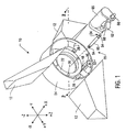
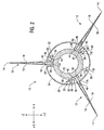
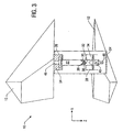
- FIGs 1-3 illustrate a particular embodiment 10 of an air or sea vehicle, non-propulsive fin control system constructed and operated in accordance with the invention.
- the control system 10 is for use with a missile. However, in alternative embodiments the control system 10 may be used with a guided bomb, a guided munition, and/or another air or sea vehicle employing non-propulsive fins.
- the control system 10 includes at least three non-propulsive fins 12, each of which provides a flight control surface 14 comprised of first and second faces 16 and 18, respectively.
- the number of flight control surfaces 14 is not material to the practice of the invention provided there are at least three. Thus, this particular embodiment may be used with any number of fins 12 greater than, or equal to, three.
- the flight control surfaces 14 control the pitch, yaw, and roll attitudes of the vehicle controlled by the control system 10.
- the control system 10 includes an actuator 20 that positions the fins 12.
- the actuator 20 comprises an actuation plane 22 and an actuation mechanism 24 capable of displacing the actuation plane at three points 26. More than three points 26 may be used in some alternative embodiments and the particular embodiment of Figures 1-3 may, in some implementations, displace the actuation plane 22 at as many as fifty points. As will be recognized by those skilled in the art having the benefit of this disclosure, the ability to use many motors as well as few motors adds flexibility to the motor selection process.
- the points 26 in the embodiment of Figures 1-3 are spaced equidistantly about the actuation plane 22, although this is not necessary to the practice of the invention.
- the actuation plane 22 may be any suitable planar member and, in the particular embodiment 10, is a rigid, uniform, aluminum ring. However, it is not necessary to the practice of the invention that the actuation plane 22 be a ring as other geometries may be used. The actuation plane 22 may even, in some embodiments, be a solid planar member (not shown). In general, the actuation plane 22 of the particular embodiment 10 illustrated should not obstruct the blast tube (not shown) if the fins 12 are deployed at the rear end of the vehicle. As will be apparent to those in the art having the benefit of this disclosure, obstruction of the blast tube is not a consideration if the fins 12 are deployed as a canard, i.e., at the front end of the vehicle.
- each linkage 28 comprises a bearing pin 30 extending from the actuation plane 22 and a fork 32 extending from a hinge pin 46.
- the bearing pin 30 includes a semi-spherical bearing 36 that fits into the notch 38 of the fork 32.
- the stem 40 of the fork 32 extends through a bore 42 in the boss 34 and an opening 44 in the hinge pin 46 of the fin 12.
- a track pin 48 also extends from the actuation plane 22 into the track 50 of a guide 52, although, in some embodiment, one of the bearing pins 30 might be used to implement the track pin 48 of the pictured embodiment.
- the bosses 34 and the guide 52 are either affixed to the fuselage 54 of the vehicle or are formed integrally therewith. Each boss 34 includes a bearing face 56 against which the actuation plane 22 moves.
- the actuation mechanism 24 is shown in an exploded, isometric view.
- the actuation mechanism 24 employs a push rod 60 and a transit 62.
- An actuator body 65 houses a drive motor (not shown) that rotates a screw 66.
- the transit 62 includes a ball screw (not shown) such that the transit 62 reciprocates as the screw 66 rotates.
- the push rod 60 includes a ball 64 at each end thereof that forms a ball joint with the actuation plane 22 and the transit 62.
- the ball joint between the push rod 60 and the actuation plane 22 forms one point 26 at which the actuation plane 22 may be displaced.
- the transit 62 includes the cup 68 in which one of the balls 64 fits to form a ball joint (not shown) between the transit 62 and the push rod 60.
- the embodiment 10 includes one actuation mechanism 24 comprising such a transit 62 and push rod 60 combination for each point 26, and may, in various embodiments, include as few as three or as many as may be desired.
- the actuation mechanism 24 may be controlled using any suitable technique known to the art and will be implementation specific.
- the actuation mechanism 24 may, in various embodiments, be electromagnetic, electromechanical, purely mechanical, hydraulic, or pneumatic. Each actuation mechanism 24 may be controlled responsive to commands issued by a person or a computer (not shown) and each may be controlled independently of the others.
- the actuation plane 22 is displaced, in the embodiment illustrated, by the actuation mechanism 24 at the points 26.
- "Displacement,” in this context, means to move by translation along the x axis and/or rotation about the y and/or z axes, where the x , y and z axes are defined as in the figures. Note that the definition of the x-z axes will vary depending on the particular embodiment being implemented although the principle of operation will remain the same. Such variations will be readily apparent to those skilled in the art and having the benefit of this disclosure. Thus, such artisans will be able to readily extrapolate the above discussion regarding the displacement of the actuation plane 22 to adjust the roll, pitch, and yaw attitudes of alternative embodiments.
- the actuation plane 22 may be displaced at any number of the points 26.
- the roll attitude of the vehicle may be controlled by displacing the actuation plane 22 along the x -axis defined in Figure 1 at each of the points 26 simultaneously.
- Unequal displacement of the actuation plane 22 along the defined x -axis at the points 26 will cause various rotations of the actuation plane 22 that will, in turn, affect the yaw and pitch attitudes of the vehicle as discussed more fully below.
- the degree of displacement may differ at various points 26 to alter combinations of the yaw, pitch, and roll attitudes of the vehicle.
- the actuation plane 22 is displaced at one or more of the points 26.
- This displacement is communicated to the fins 12 via the linkage 28. More particularly, the displacement is communicated through the bearings 36 between the pins 30 and the forks 32.
- the pin 48 in the track 50 of the guide 52 prevents the actuation plane 22 from freely rotating in the defined y-z plane about the x -axis while otherwise permitting displacement as discussed above.
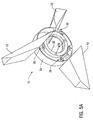
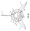
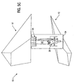
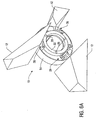
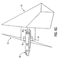
- Figures 1-3, 4A-C, and 5A-C, 6A-C illustrate operation of the invention in the context of the control system 10. More particularly:
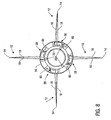
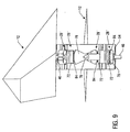
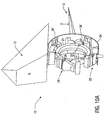
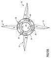
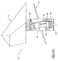
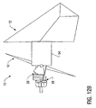
- FIGs 7-9 illustrate a non-propuslive fin control system 10' employing an alternative embodiment 28' of the linkage 28.
- the linkage 28' of this embodiment generally includes a rack 72, a rack guide 74, and a pinion gear 76.
- the rack 72 is operatively coupled to the actuation plane 22 by a pin 78 extending from the rack 72 into a socket 75 in the actuation plane 22.
- the pin 78 has a spherical head 85 that, in combination with the socket 75, permits properly constrained motion between the rack 72 and the actuation plane 22 as the actuation plane 22 is displaced.
- the rack 72 is operatively coupled to the pinion gear 76 by a toothed interface 84 such that the rack 72 and the pinion gear 76 form a rack and pinion.
- the actuation mechanism (not shown) may, in various embodiments, be electromagnetic, electromechanical, purely mechanical, hydraulic, or pneumatic.
- FIG 16A illustrates, in part, an alternative embodiment 24' of the actuation mechanism 24 as employed in the embodiment 10'.
- This actuation mechanism 24' includes two plates 80 bracketing the actuation plane 22.
- Each point 26 in this particular embodiment is constructed from paired electromagnets 82. More particularly, the interior surface 83 of each plate 80 has mounted thereon at least three electromagnets 82. Both sides 86 of the actuation plane 22 have mounted thereon, opposed to the electromagnets 82 mounted on the plates 80, at least three electromagnets 82.
- the polarities of the paired electromagnets 82 may be manipulated so that the paired electromagnets 82 attract and repel in a predetermined pattern to displace the actuation plane 22 by pushing and pulling it.
- the mounting and powering of the electromagnets 82 will be implementation specific and may be any suitable technique known to the art.
- This embodiment of the actuation mechanism 24' may also be controlled using any suitable technique known to the art and will be implementation specific. This embodiment may also be controlled responsive to commands issued by a person or a computer (not shown).
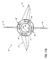
- Figures 7-9, 8A-B, 10A-C, and 10A-B illustrate operation of the invention in the context of the four fin implementation 90 of Figure 13. More particularly:
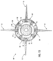
- FIGS 13-14 are cross-sectional plan views of various alternative embodiments of the system 10' illustrated in Figures 7-9 employing the invention to control four and six fins 12, respectively.
- Each fin 12 is associated with an individual linkage 28', but only a single actuator 20', in each embodiment 10'.
- Each actuator 20' is displaced longitudinally in at least three points 26, not necessarily all simultaneously, to control the yaw, pitch, and roll of the embodiment 10'.
- the invention consequently reduces the weight and complexity of actuating the fins 12 relative to the prior art by eliminating redundant actuation mechanisms.
- the linkages 28' in these particular embodiments are mounted to the interior surface 102 of the missile fuselage 54 in the annulus 92 defined by the actuator 20' and the fuselage 54.
- the actuation plane 22 of the actuator 20' encircles the rocket motor blast tube 94 in these particular embodiments.
- the invention contemplates some variation of certain structure among the many possible alternative embodiments.
- Embodiments of the actuation mechanism 24 alternative to those discussed above are contemplated and are considered to be within the scope and spirit of the invention as claimed below.
- the actuation mechanism 24 of Figures 1 and 16A are merely representative embodiments. Indeed, the precise structure of the actuation mechanism 24 is not material to the practice of the invention in all embodiments.
- the two embodiments of the actuation mechanism 24 disclosed in Figures 1 and 16A each comprise, by way of example and illustration, a particular means for displacing the actuation plane 22.
- linkage 28, including the rack 72, rack guide 74, and pinion gear 76 comprise a particular embodiment of a means for linking the actuator to the fins 12, again by way of example and illustration.
- the fins 12 and, hence, the flight control surfaces 16 and 18, are controlled by actuating the plane 22. More precisely, the fins 12 are controlled by selectively displacing the actuation plane 22 rather than rotating the fins 12 themselves, and the movement of the actuation plane 22 is then transferred over the linkage 28 to the fins 12.
- the actuation plane 22 can be rotated two-dimensionally to control yaw and pitch and translated longitudinally to control roll, all with a single actuator 20 controlling all the fins 12.
- the invention in its various embodiments, removes the design constraint of one actuator motor per fin 12.
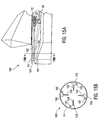
- FIGs 15A-B illustrates an alternative embodiment in which the control system 100 of Figures 7-9 may be employed to control a missile's thrust vector control system 100.
- the rack 72 is operatively coupled to a push rod 102, although the push rod may alternatively be coupled to the actuation plane 22 in some embodiments as shown in ghosted lines.
- the push rod 102 is operatively coupled to a jet vane 104 of a thrust vector control system through a gear box 103 that converts the modon of push rod 102 to rotation of the jet vane 104.
- the rack 72 reciprocates on the rack guide 74 and moves the push rod 102 therewith. This reciprocal movement is communicated to the jet vane 104 via the gear box 103 to control the thrust vector.
- FIG. 16A-C another alternative embodiment of the invention as may also be used to control a steerable nozzle thrust vector control system 110 is disclosed.
- the gear box 112 is operatively coupled to the nozzle 114 and the rack 72 and reduces the planar motion to planar rotations.
- translations of the actuation plane 22 produce no output from the gear box 112 while planar rotations produce pitch and yaw nozzle deflections.
- the fins 12 and the thrust vector may be controlled using a single actuator to actuate them using a plane.
- the particular implementation of the invention in Figures 13A-B enables implementation of fin control systems having three or more fins 12 and/or three or more thrust vector control vanes 104.
- the implementation of the invention in Figures 8A-C manifests this advantage as well. Note that the number of fins 12 and the number of thrust vector control vanes 104 need not be coincident and, in various embodiments, may differ.
Landscapes
- Engineering & Computer Science (AREA)
- Chemical & Material Sciences (AREA)
- Combustion & Propulsion (AREA)
- Mechanical Engineering (AREA)
- Ocean & Marine Engineering (AREA)
- Physics & Mathematics (AREA)
- Fluid Mechanics (AREA)
- General Engineering & Computer Science (AREA)
- Control Of Position, Course, Altitude, Or Attitude Of Moving Bodies (AREA)
Claims (17)
- Appareil pour contrôler l'attitude en roulis, en tangage, et en lacet d'un véhicule aérien ou marin, cet appareil comportant :caractérisé en ce que le moyen de commande comporte un seul plan de commande (22) ayant lesdits trois points de commande (26).un actionneur (20), incluant :un moyen de commande ; etau moins trois mécanismes de commande (24 ; 24'), capables de déplacer le moyen de commande en trois points de commande (26),au moins trois ailettes non-propulsives (12) ; etun tringlage (28 ; 28') entre l'actionneur (20) et chacune des ailettes (12), le tringlage communiquant le déplacement du moyen de commande aux ailettes respectives (12),
- Appareil selon la revendication 1, caractérisé en ce que chaque mécanisme de commande (24) comporte un moyen pour déplacer le plan de commande (22).
- Appareil selon la revendication 2, caractérisé en ce que le moyen pour déplacer est sélectionné du groupe de :deux plaques (80) disposées de part et d'autre du plan de commande (22), ces plaques (80) portant des électro-aimants (82) ayant une première polarité opposant des électro-aimants (82) montés sur le plan de commande (22) et ayant la polarité opposée, etpour chaque point de commande (26), un élément de transit (62) capable d'appliquer à une tige de poussée (60) un mouvement de va-et-vient en vue de déplacer le plan de commande (22) au point respectif.
- Appareil selon la revendication 2, caractérisé en ce que le moyen pour déplacer emploie un principe sélectionné du groupe électromagnétique, électromécanique, mécanique, hydraulique et pneumatique.
- Appareil selon la revendication 1, caractérisé en ce que le mécanisme de commande (24, 24') est sélectionné du groupe de :deux plaques (80) disposées de part et d'autre du plan de commande (22), ces plaques (80) portant des électro-aimants (82) ayant une première polarité opposant des électro-aimants (82) montés sur le plan de commande (22) et ayant la polarité opposée, etpour chaque point de commande (26), un élément de transit (62) capable d'appliquer à une tige de poussée (60) un mouvement de va-et-vient en vue de déplacer le plan de commande (22) au point respectif.
- Appareil selon la revendication 1, caractérisé en ce que le mécanisme de commande (24, 24') emploie un principe sélectionné du groupe électromagnétique, électromécanique, mécanique, hydraulique et pneumatique.
- Appareil selon la revendication 1, caractérisé en ce que le tringlage (28') comporte :une crémaillère (72) couplée de façon opérationnelle au plan de commande (22) ;un guide-crémaillère (74) pour guider la crémaillère (72), etun pignon (76) couplé de façon opérationnelle à la crémaillère (72) et à l'ailette (12).
- Appareil selon la revendication 1, caractérisé en ce que le véhicule comporte un fuselage (54), chaque ailette (12) incluant une tige de pivot s'étendant à travers le fuselage (54), chaque tige de pivot (46) ayant un alésage (44) formé à travers la tige, et le tringlage (28) comportant :une pluralité de tiges de palier (30) s'étendant du plan de commande (22) ;une bosse (34) pour chaque ailette (12) et attachée au fuselage (54) du véhicule ;une pluralité de fourches (32), chaque fourche (32) s'étendant par une bosse respective (34) et dans l'alésage (44) de chaque tige de pivot respective (46) ;un palier (36) disposé entre chaque tige de palier (30) et une fourche respective de la pluralité de fourches (32) ; etun moyen pour empêcher la libre rotation du plan de commande (32).
- Appareil selon la revendication 8, caractérisé en ce que le moyen pour empêcher la libre rotation comporte :un moyen de guidage (52) attaché au fuselage (54) du véhicula, ce moyen de guidage (52) ayant une glissière (50) pratiquée dans le moyen de guidage ; etune tige de guidage (48) s'étendant du plan de commande (22) et reçue dans la glissière (50).
- Appareil selon la revendication 9, caractérisé en ce que la tige de guidage (48) est une quelconque des tiges de palier (30).
- Appareil selon la revendication 1, caractérisé en ce que les mécanismes de commande (24 ; 24') déplacent le plan de commande (22) simultanément aux trois points de commande (26).
- Appareil selon la revendication 1, caractérisé en ce que le plan de commande (22) est un anneau.
- Appareil selon la revendication 1, caractérisé en ce que le tringlage (28 ; 28') est couplé de façon opérationnelle à un système de contrôle d'un vecteur de poussée (100 ; 110).
- Appareil selon la revendication 1, caractérisé en ce que le plan de commande (22) est positionné dans un espace annulaire défini par un fuselage (54) et un tube de soufflage.
- Procédé pour contrôler en tangage, en roulis et en lacet un véhicule aérien ou marin ayant au moins trois ailettes (12) formant des surfaces de contrôle du véhicule, ce procédé étant caractérisé par la commande des au moins trois ailettes (12) au moyen d'un seul plan de commande (12) pour affecter le mouvement en tangage, en lacet et en roulis.
- Procédé selon la revendication 15, caractérisé en ce que la commande les ailettes (12) par un seul plan de commande (22) comporte les actions de :connecter les au moins trois ailettes (12) audit plan de commande (22) ; et dedéplacer le plan de commande (22) en trois points différents afin d'actionner les ailettes (12).
- Procédé selon la revendication 16, caractérisé en ce que l'étape de déplacer le plan de commande (22) comprend l'action de déplacer le plan de commande (22) simultanément aux trois points différents (26).
Applications Claiming Priority (3)
| Application Number | Priority Date | Filing Date | Title |
|---|---|---|---|
| US110504 | 1993-08-20 | ||
| US09/110,504 US6247666B1 (en) | 1998-07-06 | 1998-07-06 | Method and apparatus for non-propulsive fin control in an air or sea vehicle using planar actuation |
| PCT/US1999/015373 WO2000002003A1 (fr) | 1998-07-06 | 1999-07-02 | Procede et appareil de commande d'ailettes non propulsives pour engin aerien ou aquatique par actionnement plan |
Publications (2)
| Publication Number | Publication Date |
|---|---|
| EP1009966A1 EP1009966A1 (fr) | 2000-06-21 |
| EP1009966B1 true EP1009966B1 (fr) | 2003-01-22 |
Family
ID=22333367
Family Applications (1)
| Application Number | Title | Priority Date | Filing Date |
|---|---|---|---|
| EP99932336A Expired - Lifetime EP1009966B1 (fr) | 1998-07-06 | 1999-07-02 | Procede et appareil de commande d'ailettes non propulsives dans un vehicule air ou mer par actionnement plan |
Country Status (5)
| Country | Link |
|---|---|
| US (1) | US6247666B1 (fr) |
| EP (1) | EP1009966B1 (fr) |
| AU (1) | AU4866399A (fr) |
| DE (1) | DE69905005T2 (fr) |
| WO (1) | WO2000002003A1 (fr) |
Families Citing this family (32)
| Publication number | Priority date | Publication date | Assignee | Title |
|---|---|---|---|---|
| US6543720B2 (en) * | 1998-10-13 | 2003-04-08 | Paul Vincent Ladd | Directional control and aerofoil system for aircraft |
| US6360987B1 (en) * | 2000-05-23 | 2002-03-26 | Bae Systems Integrated Defense Solutions | Methods and apparatus for swash plate guidance and control |
| US6723972B2 (en) * | 2000-12-22 | 2004-04-20 | Lockheed Martin Corporation | Method and apparatus for planar actuation of a flared surface to control a vehicle |
| SE521445C2 (sv) * | 2001-03-20 | 2003-11-04 | Bofors Defence Ab | Sätt att synkronisera fenutfällningen vid en fenstabiliserad artillerigranat samt en i enlighet därmed utformad artillerigranat |
| US6637699B2 (en) | 2002-03-25 | 2003-10-28 | Lockheed Martin Corporation | Method and apparatus for controlling a trajectory of a projectile |
| US6691948B1 (en) | 2003-04-10 | 2004-02-17 | The United States Of America As Represented By The Secretary Of The Navy | High torque rocket nozzle |
| US6869044B2 (en) * | 2003-05-23 | 2005-03-22 | Raytheon Company | Missile with odd symmetry tail fins |
| US6752352B1 (en) * | 2003-07-07 | 2004-06-22 | Michael C. May | Gun-launched rolling projectile actuator |
| US7255304B2 (en) * | 2003-12-08 | 2007-08-14 | General Dynamics Ordnance And Tactical Systems, Inc. | Tandem motor actuator |
| US7262394B2 (en) * | 2004-03-05 | 2007-08-28 | The Boeing Company | Mortar shell ring tail and associated method |
| US7219579B2 (en) * | 2004-03-10 | 2007-05-22 | Lockheed Martin Corporation | Apparatus and method for actuating control surfaces |
| US7804053B2 (en) * | 2004-12-03 | 2010-09-28 | Lockheed Martin Corporation | Multi-spectral direction finding sensor having plural detection channels capable of collecting plural sets of optical radiation with different bandwidths |
| FR2891618B1 (fr) * | 2005-10-05 | 2010-06-11 | Giat Ind Sa | Dispositif d'entrainement de gouvernes de projectile. |
| WO2007044977A2 (fr) * | 2005-10-13 | 2007-04-19 | Raytheon Company | Ensemble d'echappement pour systeme d'entrainement d'ejection de matiere |
| US8080772B2 (en) * | 2007-11-02 | 2011-12-20 | Honeywell International Inc. | Modular, harnessless electromechanical actuation system assembly |
| WO2010019299A2 (fr) * | 2008-05-21 | 2010-02-18 | Raytheon Company | Système intégré de contrôle du vecteur de poussée et de contrôle en roulis |
| US8878111B2 (en) | 2009-02-24 | 2014-11-04 | Blue Origin, Llc | Bidirectional control surfaces for use with high speed vehicles, and associated systems and methods |
| EP2401204A4 (fr) * | 2009-02-24 | 2017-07-05 | Blue Origin, LLC | Véhicules de lancement avec surfaces de décélération fixes et déployables, et/ou réservoirs de combustible façonnés, et systèmes et procédés associés |
| JP2012530020A (ja) * | 2009-06-15 | 2012-11-29 | ブルー オリジン エルエルシー | 宇宙打ち上げ機の海上着陸及び関連のシステム及び方法 |
| US8436285B2 (en) * | 2010-07-26 | 2013-05-07 | Raytheon Company | Projectile that includes a fin adjustment mechanism with changing backlash |
| FR2995074A1 (fr) * | 2012-08-31 | 2014-03-07 | Nexter Munitions | Projectile a gouvernes orientables et procede de commande des gouvernes d'un tel projectile |
| US9086258B1 (en) * | 2013-02-18 | 2015-07-21 | Orbital Research Inc. | G-hardened flow control systems for extended-range, enhanced-precision gun-fired rounds |
| US9487308B2 (en) | 2013-03-15 | 2016-11-08 | Blue Origin, Llc | Launch vehicles with ring-shaped external elements, and associated systems and methods |
| FR3041744B1 (fr) * | 2015-09-29 | 2018-08-17 | Nexter Munitions | Projectile d'artillerie ayant une phase pilotee. |
| US10822122B2 (en) | 2016-12-28 | 2020-11-03 | Blue Origin, Llc | Vertical landing systems for space vehicles and associated methods |
| US11300390B1 (en) | 2018-03-05 | 2022-04-12 | Dynamic Structures And Materials, Llc | Control surface deployment apparatus and method of use |
| US11560243B2 (en) | 2019-02-22 | 2023-01-24 | Blue Origin, Llc | Spacecraft multifunction connecting mechanisms including interchangeable port opening docking mechanisms, and associated systems and methods |
| US11565628B2 (en) | 2019-03-29 | 2023-01-31 | Blue Origin, Llc | Spacecraft with increased cargo capacities, and associated systems and methods |
| US11650033B2 (en) * | 2020-12-04 | 2023-05-16 | Bae Systems Information And Electronic Systems Integration Inc. | Control plate-based control actuation system |
| CN112810788B (zh) * | 2021-01-18 | 2022-01-14 | 镇江同舟螺旋桨有限公司 | 一种海洋船只推进器的液压转向装置 |
| US12326323B2 (en) * | 2021-01-22 | 2025-06-10 | Bae Systems Controls Inc. | Anti-backlash apparatus and an actuator with anti-backlash transmission |
| US11987395B2 (en) | 2021-06-07 | 2024-05-21 | Blue Origin, Llc | Thrusting rails for launch vehicles, and associated systems and methods |
Family Cites Families (11)
| Publication number | Priority date | Publication date | Assignee | Title |
|---|---|---|---|---|
| US2873074A (en) * | 1953-10-09 | 1959-02-10 | Sperry Rand Corp | Flight control system |
| US2868478A (en) | 1954-05-05 | 1959-01-13 | Mccloughy Thomas | Rocket control |
| US3355130A (en) | 1965-12-10 | 1967-11-28 | Vernon C Dell | Anti-squeeze mode control surface mechanism |
| US3415467A (en) * | 1967-01-30 | 1968-12-10 | Joseph A. Barringer | Retrievable rocket with folded wings |
| US4210298A (en) | 1978-08-01 | 1980-07-01 | The United States Of America As Represented By The Secretary Of The Army | Electro-mechanical guidance actuator for a missile |
| FR2450444A1 (fr) | 1979-02-28 | 1980-09-26 | Aerospatiale | Procede electromagnetique pour regler l'orientation d'une plate-forme |
| GB2086321B (en) | 1979-08-15 | 1983-02-02 | British Aerospace | Jet propulsion nozzle assemblies |
| JPS58500493A (ja) | 1981-04-08 | 1983-03-31 | オ−ストラリア国 | 空中または水中ミサイル用方向制御装置 |
| DE8514910U1 (de) | 1985-05-21 | 1986-11-27 | Messerschmitt-Bölkow-Blohm GmbH, 8012 Ottobrunn | Steuerungseinrichtung zur Rotorblattverstellung, insbesondere eines Drehflügelflugzeugs |
| DE3717688C1 (en) * | 1987-05-26 | 1988-06-09 | Messerschmitt Boelkow Blohm | Rotating device for aerodynamically acting control surfaces which are mounted such that they can rotate |
| FR2657703B1 (fr) | 1990-01-26 | 1992-04-10 | Thomson Brandt Armements | Dispositif pour la commande d'attitude en roulis d'un projectile stabilise par empennage. |
-
1998
- 1998-07-06 US US09/110,504 patent/US6247666B1/en not_active Expired - Fee Related
-
1999
- 1999-07-02 AU AU48663/99A patent/AU4866399A/en not_active Abandoned
- 1999-07-02 DE DE69905005T patent/DE69905005T2/de not_active Expired - Lifetime
- 1999-07-02 EP EP99932336A patent/EP1009966B1/fr not_active Expired - Lifetime
- 1999-07-02 WO PCT/US1999/015373 patent/WO2000002003A1/fr not_active Ceased
Also Published As
| Publication number | Publication date |
|---|---|
| WO2000002003A1 (fr) | 2000-01-13 |
| EP1009966A1 (fr) | 2000-06-21 |
| AU4866399A (en) | 2000-01-24 |
| WO2000002003A9 (fr) | 2000-07-20 |
| DE69905005D1 (de) | 2003-02-27 |
| US6247666B1 (en) | 2001-06-19 |
| DE69905005T2 (de) | 2003-09-25 |
Similar Documents
| Publication | Publication Date | Title |
|---|---|---|
| EP1009966B1 (fr) | Procede et appareil de commande d'ailettes non propulsives dans un vehicule air ou mer par actionnement plan | |
| US5630564A (en) | Differential yoke-aerofin thrust vector control system | |
| US5887821A (en) | Mechanism for thrust vector control using multiple nozzles and only two yoke plates | |
| US4274610A (en) | Jet tab control mechanism for thrust vector control | |
| US9120557B2 (en) | Piloting device for piloting a vehicle, in particular an aircraft | |
| US5662290A (en) | Mechanism for thrust vector control using multiple nozzles | |
| US6723972B2 (en) | Method and apparatus for planar actuation of a flared surface to control a vehicle | |
| EP3668786B1 (fr) | Système d'actionnement | |
| EP0489712B1 (fr) | Dispositif de guidage pour missile utilisant le contrÔle de la poussée | |
| US6364248B1 (en) | Articulated nose missile control actuation system | |
| US20160194089A1 (en) | Vehicle attitude control using jet paddles and/or movable mass | |
| US4699333A (en) | On-board flight control panel system | |
| CN113924413B (zh) | 用于推进装置的推进单元和相关联的推进装置 | |
| JP2024544824A (ja) | プロペラの軸の移動が可能なドローン | |
| US7692127B1 (en) | MEMS type thermally actuated out-of-plane lever | |
| US20120042628A1 (en) | Robotic manipulator | |
| US11892275B2 (en) | Drive mechanism for control surface actuation | |
| US4892253A (en) | Yoke nozzle actuation system | |
| US6646242B2 (en) | Rotational canted-joint missile control system | |
| US11650033B2 (en) | Control plate-based control actuation system | |
| US11933587B1 (en) | Articulated head and actuation system for a missile | |
| US6460801B1 (en) | Precision guidance system for aircraft launched bombs | |
| KR102692544B1 (ko) | 변위 이동형 구동장치 및 이를 포함하는 유도 비행체 | |
| RU2015496C1 (ru) | Отклоняемая головная часть ракеты | |
| CN121929308A (zh) | 一种球铰式飞行器头部偏转机构及其控制方法 |
Legal Events
| Date | Code | Title | Description |
|---|---|---|---|
| PUAI | Public reference made under article 153(3) epc to a published international application that has entered the european phase |
Free format text: ORIGINAL CODE: 0009012 |
|
| AK | Designated contracting states |
Kind code of ref document: A1 Designated state(s): DE FR GB |
|
| 17P | Request for examination filed |
Effective date: 20000608 |
|
| 17Q | First examination report despatched |
Effective date: 20010308 |
|
| GRAG | Despatch of communication of intention to grant |
Free format text: ORIGINAL CODE: EPIDOS AGRA |
|
| GRAG | Despatch of communication of intention to grant |
Free format text: ORIGINAL CODE: EPIDOS AGRA |
|
| GRAG | Despatch of communication of intention to grant |
Free format text: ORIGINAL CODE: EPIDOS AGRA |
|
| GRAH | Despatch of communication of intention to grant a patent |
Free format text: ORIGINAL CODE: EPIDOS IGRA |
|
| GRAH | Despatch of communication of intention to grant a patent |
Free format text: ORIGINAL CODE: EPIDOS IGRA |
|
| GRAA | (expected) grant |
Free format text: ORIGINAL CODE: 0009210 |
|
| AK | Designated contracting states |
Kind code of ref document: B1 Designated state(s): DE FR GB |
|
| REG | Reference to a national code |
Ref country code: GB Ref legal event code: FG4D |
|
| REF | Corresponds to: |
Ref document number: 69905005 Country of ref document: DE Date of ref document: 20030227 Kind code of ref document: P |
|
| ET | Fr: translation filed | ||
| PLBE | No opposition filed within time limit |
Free format text: ORIGINAL CODE: 0009261 |
|
| STAA | Information on the status of an ep patent application or granted ep patent |
Free format text: STATUS: NO OPPOSITION FILED WITHIN TIME LIMIT |
|
| 26N | No opposition filed |
Effective date: 20031023 |
|
| PGFP | Annual fee paid to national office [announced via postgrant information from national office to epo] |
Ref country code: FR Payment date: 20100805 Year of fee payment: 12 |
|
| PGFP | Annual fee paid to national office [announced via postgrant information from national office to epo] |
Ref country code: GB Payment date: 20100726 Year of fee payment: 12 |
|
| PGFP | Annual fee paid to national office [announced via postgrant information from national office to epo] |
Ref country code: DE Payment date: 20110727 Year of fee payment: 13 |
|
| GBPC | Gb: european patent ceased through non-payment of renewal fee |
Effective date: 20110702 |
|
| REG | Reference to a national code |
Ref country code: FR Ref legal event code: ST Effective date: 20120330 |
|
| PG25 | Lapsed in a contracting state [announced via postgrant information from national office to epo] |
Ref country code: FR Free format text: LAPSE BECAUSE OF NON-PAYMENT OF DUE FEES Effective date: 20110801 |
|
| PG25 | Lapsed in a contracting state [announced via postgrant information from national office to epo] |
Ref country code: GB Free format text: LAPSE BECAUSE OF NON-PAYMENT OF DUE FEES Effective date: 20110702 |
|
| PG25 | Lapsed in a contracting state [announced via postgrant information from national office to epo] |
Ref country code: DE Free format text: LAPSE BECAUSE OF NON-PAYMENT OF DUE FEES Effective date: 20130201 |
|
| REG | Reference to a national code |
Ref country code: DE Ref legal event code: R119 Ref document number: 69905005 Country of ref document: DE Effective date: 20130201 |