EP1010469A2 - Système et procédé d'alimentation en peinture d'une installation de revêtement électrostatique - Google Patents
Système et procédé d'alimentation en peinture d'une installation de revêtement électrostatique Download PDFInfo
- Publication number
- EP1010469A2 EP1010469A2 EP99123855A EP99123855A EP1010469A2 EP 1010469 A2 EP1010469 A2 EP 1010469A2 EP 99123855 A EP99123855 A EP 99123855A EP 99123855 A EP99123855 A EP 99123855A EP 1010469 A2 EP1010469 A2 EP 1010469A2
- Authority
- EP
- European Patent Office
- Prior art keywords
- container
- point
- material removal
- containers
- spray device
- Prior art date
- Legal status (The legal status is an assumption and is not a legal conclusion. Google has not performed a legal analysis and makes no representation as to the accuracy of the status listed.)
- Granted
Links
Images

Classifications
-
- B—PERFORMING OPERATIONS; TRANSPORTING
- B05—SPRAYING OR ATOMISING IN GENERAL; APPLYING FLUENT MATERIALS TO SURFACES, IN GENERAL
- B05B—SPRAYING APPARATUS; ATOMISING APPARATUS; NOZZLES
- B05B5/00—Electrostatic spraying apparatus; Spraying apparatus with means for charging the spray electrically; Apparatus for spraying liquids or other fluent materials by other electric means
- B05B5/16—Arrangements for supplying liquids or other fluent material
- B05B5/1608—Arrangements for supplying liquids or other fluent material the liquid or other fluent material being electrically conductive
- B05B5/1616—Arrangements for supplying liquids or other fluent material the liquid or other fluent material being electrically conductive and the arrangement comprising means for insulating a grounded material source from high voltage applied to the material
- B05B5/1625—Arrangements for supplying liquids or other fluent material the liquid or other fluent material being electrically conductive and the arrangement comprising means for insulating a grounded material source from high voltage applied to the material the insulating means comprising an intermediate container alternately connected to the grounded material source for filling, and then disconnected and electrically insulated therefrom
- B05B5/1633—Arrangements for supplying liquids or other fluent material the liquid or other fluent material being electrically conductive and the arrangement comprising means for insulating a grounded material source from high voltage applied to the material the insulating means comprising an intermediate container alternately connected to the grounded material source for filling, and then disconnected and electrically insulated therefrom the arrangement comprising several supply lines arranged in parallel, each comprising such an intermediate container
-
- B—PERFORMING OPERATIONS; TRANSPORTING
- B05—SPRAYING OR ATOMISING IN GENERAL; APPLYING FLUENT MATERIALS TO SURFACES, IN GENERAL
- B05B—SPRAYING APPARATUS; ATOMISING APPARATUS; NOZZLES
- B05B12/00—Arrangements for controlling delivery; Arrangements for controlling the spray area
- B05B12/14—Arrangements for controlling delivery; Arrangements for controlling the spray area for supplying a selected one of a plurality of liquids or other fluent materials or several in selected proportions to a spray apparatus, e.g. to a single spray outlet
- B05B12/1463—Arrangements for controlling delivery; Arrangements for controlling the spray area for supplying a selected one of a plurality of liquids or other fluent materials or several in selected proportions to a spray apparatus, e.g. to a single spray outlet separate containers for different materials to be sprayed being moved from a first location, e.g. a filling station, where they are fluidically disconnected from the spraying apparatus, to a second location, generally close to the spraying apparatus, where they are fluidically connected to the latter
Definitions
- the invention relates to a method and a system for Paint supply according to an electrostatic coating system the preamble of the independent claims, in particular suitable for the series coating of vehicle bodies are.
- the Invention the object of a method and system for Paint supply for an electrostatic coating system exchangeable containers that can be fed with the spray device for water-based paint or similar conductive coating material specify, where the basic Advantages of the known system that applied to the spray device High voltage not switched off when changing containers must be, so that there is the possibility of the coating company not to be interrupted when changing containers.
- the invention has the advantage that an endless coating from an unlimited number of containers is enabled, which after use continuously without interruption of the coating company against new containers Color types can be changed as long as no color change is required. Even the color change can be done with the least possible Wasted time.
- the system shown in Fig. 1 is used for paint supply a spray device that is continuously under high voltage 10, e.g. one or usually several electrostatic Rotary atomizers in the usual way with upstream metering pump 11 can exist.
- the spray device 10 is a distribution valve arrangement 12 upstream, on the two lines 14 and 15 serving as color channels are connected or can be connected via the distribution valves can optionally be connected to the spray device 10.
- the spray device 10, the distributor valve arrangement 12 and the separating clutches 16, 17 can are located in a movable coating machine part 18, for example in the roof beam of a conventional roof machine for the automotive coating.
- the lines consisting of flexible hoses 14 and 15 are arranged with high voltage insulation against earth and lead at their ends facing away from the spray device 10 in a material removal point, which is also insulated from the earth 1 or 2 in a total of 20 Container change area, which is in a constantly grounded Part in or next to the machine or coating system located and can be stationary.
- the material change area 20 also includes various grounded ones Supply points 3, 4, 4 'and 4' 'for the material removal points 1, 2 interchangeable containers to be used (which in 1 are not shown). After insertion into the supply point 3, which has a color change valve arrangement FW is connected to ring lines in the usual way emptied containers for reuse in the container change area 20 to be filled by yourself. At the supply points 4 to 4 '', which can serve as buffer spaces on the other hand, externally filled containers are provided and / or after Use can be removed again from the container change area 20.
- the system can at the buffer or supply points 4, 4 'and / or 4' ' can also be manually loaded with containers, which is especially for Containers with special colors that are rarely needed are useful can be and providing a virtually unlimited Wide range of colors available. Also a rotating one Container magazine (not shown) for a variety of interchangeable Container can be at one of the supply points 4, 4 ' or 4 '' can be provided.
- the container changing device arranged in the area 20 consists mainly of a rotatable grounded Turntable 22 on which two gripping devices 23 and 23 ' are mounted.
- Each gripping device has a drive device 24 or 24 ', for example in the form of a pneumatic Piston and cylinder unit for a preferably straight, e.g. rod-like insulating arm 25 or 25 ', at its free end a gripper 26 or 26 'is arranged.
- the grippers 26 and 26 ' can be made of metal. Arrangement and formation of the isolating arm 25, 25 'are such that the gripper 26, 26' when inserted a container in the material removal points 1, 2 against the grounded parts of the gripping device connected to the gripper 23, 23 'is isolated.
- the two grippers 26, 26 ' can be moved independently of each other.
- the grippers 26, 26 ' via a also for high voltage insulation of the Spray device 10 at high voltage material removal points 1, 2 insulating distance measured against earth moves the between the material removal points and the earthed parts the gripping devices 23, 23 'and the turntable 22 are formed is.
- the insulating section is indicated by arrow 30 and forms one to the axis of rotation in the example shown of the turntable 22 concentric arcuate insulating area parallel in a horizontal plane in the example described to the directions of movement of the grippers.
- the two isolated material removal points are located accordingly 1, 2 on a concentric to the rotary table axis Circular arc on which is also used to supply the system supply points 3 filled with containers, 4, 4 'and 4' ', so that they are just like the material removal points 1, 2 accessible from each of the two grippers 26, 26 ' are.
- the linear directions of movement of the two grippers 26 and 26 ' can be in accordance with FIG. 1 at or in the material removal points 1, 2 and consequently also at or in the supply point 3, 4, 4 'or 4' 'to which they cut from the rotary table 22 can be pivoted. This ensures that in each case the one gripper a container on the concerned Place to pick up or pick up while at the same turntable position the other gripper there another container can pick up or use.
- the container changing devices and their grippers can Program control so that in DE patent application 198 38 805 described system correspond.
- the interchangeable containers can be found in EP 0 796 664 and 0 796 665 correspond to the dosing cylinders described here but preferably by pressurizing its interior Pistons can be emptied.
- the second container After filling the second container becomes one of the gripping devices 23 or 23 'removed from the supply point 3 by turning of the turntable 22 in the shown in the drawing for Reaching the second material removal point 2 required Position pivoted and then by extending the concerned Gripper 26 or 26 'over the insulating section 30 in the live material removal point 2 used.
- the container There is the container that has been at earth potential until then automatically to the high voltage potential of the spray device raised, a possibly undesirable to sudden Potential changes can be avoided by suitable means can.
- the second container can be opened by opening the corresponding one Valve of the distribution valve assembly 12 to the first container connected in parallel, ie with the same spray device 10 Material removal can be connected. The spray operation can thus continue without interruption.
- the distributor valve arrangement 12 usually connects the distributor valve arrangement 12 only then the second container with the spraying device if, after emptying the first Container whose connection has broken. While the spray device 10 is now supplied from the second container the first container can be removed from one of the gripping devices 23 or 23 'removed from the material removal point 1 and either be brought to the supply point 3 for filling or instead to one of the buffer supply points 4, 4 ' or 4 '' where it is removed from the system and against an external one filled container can be replaced.
- the separating clutches 16 and 17 are not described here Additional functions especially when changing colors expedient. For similar reasons, lead from the manifold valve assembly 12 on the illustrated additional separating clutches insulated flush and return hoses 33 and from the Material removal points 1 and 2 additional return lines 31 from the movable machine part 18 or from the container changing area 20 out.
- the separating clutches 16 and 17 could with the continuous spray operation described but possibly also for high voltage insulation of the spray device 12 serve from the grounded material changing device, especially if a container changing device without the Insulated gripper function is provided.
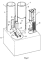
- the two material removal points 1 and 2 each in a cylinder housing 41 or 42 made of insulating material.
- the the two cylinder housings 41, 42 are vertical with their longitudinal axes on a stationary base in or next to the coating machine, that is, perpendicular to that assumed to be horizontal Plane of motion of the isolating arms shown at 43 Gripping devices (23 in Fig. 1).
- In the cylinder housings 41 and 42 are all fixed parts of the material removal points 1, 2 included, which are placed on high voltage.
- an insulating arm 25 or 25 'in the form of a straight have elongated body made of insulating material, which on his one, the material removal points 1, 2 facing away from the end Piston serving as a drive device 24 (FIG. 1) pneumatic cylinder unit 44 is attached.
- the insulating arm 25, 25 ' carries an elongated, with its longitudinal axis vertical, that is, transverse to the plane of movement of the insulating arms extending housing 46 or 46 ' Made of insulating material that is attached to the end face of the insulating arm is scheduled.
- this insulating housing 46 for example housed metallic gripper elements with which the Gripping device 43 releasably on holding elements (not shown) on the cylindrical outside of the replaceable, can attack at 48 recognizable paint containers.
- the total length of the insulating arm 25 and the insulated housing 46 formed insulating body is dimensioned so that for a given High voltage required insulation between the metallic Gripper elements and earth is guaranteed.
- color change valve arrangement FW shown in more detail in Fig. 2nd without paint container.
- the color change valve arrangement FW is with connected to a connecting part 50 which contains valve openings, to the openings provided in the bottom of the cylindrical paint containers be coupled for filling.
- Corresponding connection openings are on the floor of the material removal points 1 and 2 within the cylinder housing 41 or 42 for the removal of material from the containers.
- the insulating cylinder housings 41, 42 have a cylindrical shape Wall each an opening facing the turntable 22 52 for inserting the container 48.
- the opening 52 is dimensioned so that the container together with the insulating housing 46 the relevant gripping device 43 can pass through.
- the opening 52 through one of the cylindrical outer wall correspondingly curved shield-like cover 54 made of insulating material closed, only for insertion and removal a container to open the opening 52 pushed away will, so that during the rest of the time everyone is on high voltage lying parts of the container changing area 20 (FIG. 1) safely are included. This has the advantage of reducing the Space requirements.
- the turntable 22 is preferably made of metal and is like the cylinder units 44 and all others on that of the cylinder housings 41, 42 facing away from the insulating arms 25, 25 ' conductive parts are permanently grounded.
- Fig. 2 shows the one gripping device 43 for example Removing a first container from the cylinder housing 41 one material removal point 1, while the second gripping device 43 'another container 48 outside the material removal points for insertion in the same cylinder housing 41 ready.
- the first container from the tapping point 1 removed and returned to the grounded turntable 22 , it is also above the discharge resistance mentioned above connected to earth.
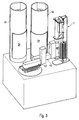
- Fig. 3 the changing device is in the subsequent Position shown in which the second container 48 in the now again closed cylinder housing 41 inserted and that of first containers 48 'removed there by the gripping device 43 in the supply point 3 to the color change valve arrangement has been connected.
- Deviating from the arrangement shown in Fig. 1 are here the two gripping devices 43 and 43 'are not so on the turntable 22 mounted that their directions of movement in the material removal points Cut 1 and 2. To reduce the Rather, they are space-consuming in close proximity with each other parallel (or at a small angle to each other inclined) directions of movement of their insulating arms 25, 25 'mounted. Because of this less bulky arrangement, the turntable must 22 between the removal of a container and the insertion of the new container 48 provided in the same material removal point 1 make a small angular movement to the new container in the position required for insertion bring to.
Landscapes
- Electrostatic Spraying Apparatus (AREA)
- Application Of Or Painting With Fluid Materials (AREA)
- Spray Control Apparatus (AREA)
Applications Claiming Priority (2)
| Application Number | Priority Date | Filing Date | Title |
|---|---|---|---|
| DE19858397A DE19858397A1 (de) | 1998-12-17 | 1998-12-17 | Verfahren und System zur Farbversorgung einer elektrostatischen Beschichtungsanlage |
| DE19858397 | 1998-12-17 |
Publications (3)
| Publication Number | Publication Date |
|---|---|
| EP1010469A2 true EP1010469A2 (fr) | 2000-06-21 |
| EP1010469A3 EP1010469A3 (fr) | 2003-02-05 |
| EP1010469B1 EP1010469B1 (fr) | 2006-11-02 |
Family
ID=7891514
Family Applications (1)
| Application Number | Title | Priority Date | Filing Date |
|---|---|---|---|
| EP99123855A Expired - Lifetime EP1010469B1 (fr) | 1998-12-17 | 1999-12-01 | Système et procédé d'alimentation en peinture d'une installation de revêtement électrostatique |
Country Status (4)
| Country | Link |
|---|---|
| EP (1) | EP1010469B1 (fr) |
| AT (1) | ATE344103T1 (fr) |
| DE (2) | DE19858397A1 (fr) |
| ES (1) | ES2274601T3 (fr) |
Families Citing this family (5)
| Publication number | Priority date | Publication date | Assignee | Title |
|---|---|---|---|---|
| DE19940542A1 (de) * | 1999-08-26 | 2001-03-01 | Abb Patent Gmbh | Verfahren und Anordnung zum Transport von elektrisch leitfähigem Lack |
| DE19940541A1 (de) * | 1999-08-26 | 2001-03-01 | Abb Patent Gmbh | Verfahren und Anordnung zum Transport von elektrisch leitfähigem Lack |
| DE10059041C2 (de) | 2000-11-28 | 2002-11-14 | Lactec Ges Fuer Moderne Lackte | Verfahren und Vorrichtung zum Fördern von elektrisch leitfähigen Lacken zwischen unterschiedlichen Spannungspotenzialen |
| DE10120272A1 (de) | 2001-04-25 | 2002-10-31 | Duerr Systems Gmbh | Verfahren zur Betriebssteuerung einer Beschichtungsanlage |
| DE10145169A1 (de) | 2001-09-13 | 2003-04-03 | Duerr Systems Gmbh | Verfahren zum serienweisen Beschichten von Werkstücken |
Citations (5)
| Publication number | Priority date | Publication date | Assignee | Title |
|---|---|---|---|---|
| DE2900660A1 (de) | 1978-01-11 | 1979-07-19 | Akzo Gmbh | Verfahren und vorrichtung zum elektrostatischen spritzen von elektrisch leitfaehigen lacken |
| US4313475A (en) | 1980-06-26 | 1982-02-02 | The Gyromat Corporation | Voltage block system for electrostatic coating with conductive materials |
| US4785760A (en) | 1987-01-02 | 1988-11-22 | S A M E S S.A. | Sprayer installation |
| EP0455109A2 (fr) | 1990-04-30 | 1991-11-06 | Dürr GmbH | Procédé et installation de revêtement en series de pièces avec un produit de revêtement conducteur |
| EP0455107A2 (fr) | 1990-04-30 | 1991-11-06 | Dürr GmbH | Procédé et installation de revêtement en séries de pièces avec un produit de revêtement conducteur |
Family Cites Families (4)
| Publication number | Priority date | Publication date | Assignee | Title |
|---|---|---|---|---|
| US5549755A (en) * | 1994-12-08 | 1996-08-27 | Nordson Corporation | Apparatus for supplying conductive coating materials including transfer units having a combined shuttle and pumping device |
| JP3245040B2 (ja) * | 1996-02-29 | 2002-01-07 | トリニティ工業株式会社 | 静電塗装機 |
| DE19610588B4 (de) * | 1996-03-18 | 2010-08-05 | Dürr Systems GmbH | Beschichtungsmaschine mit auswechselbarem Behälter |
| DE19610589A1 (de) * | 1996-03-18 | 1997-09-25 | Duerr Gmbh & Co | Verfahren und System zur Farbversorgung einer Beschichtungsanlage |
-
1998
- 1998-12-17 DE DE19858397A patent/DE19858397A1/de not_active Ceased
-
1999
- 1999-12-01 EP EP99123855A patent/EP1010469B1/fr not_active Expired - Lifetime
- 1999-12-01 DE DE59913959T patent/DE59913959D1/de not_active Expired - Lifetime
- 1999-12-01 ES ES99123855T patent/ES2274601T3/es not_active Expired - Lifetime
- 1999-12-01 AT AT99123855T patent/ATE344103T1/de not_active IP Right Cessation
Patent Citations (6)
| Publication number | Priority date | Publication date | Assignee | Title |
|---|---|---|---|---|
| DE2900660A1 (de) | 1978-01-11 | 1979-07-19 | Akzo Gmbh | Verfahren und vorrichtung zum elektrostatischen spritzen von elektrisch leitfaehigen lacken |
| US4313475A (en) | 1980-06-26 | 1982-02-02 | The Gyromat Corporation | Voltage block system for electrostatic coating with conductive materials |
| US4313475B1 (en) | 1980-06-26 | 1994-07-12 | Nordson Corp | Voltage block system for electrostatic coating with conductive materials |
| US4785760A (en) | 1987-01-02 | 1988-11-22 | S A M E S S.A. | Sprayer installation |
| EP0455109A2 (fr) | 1990-04-30 | 1991-11-06 | Dürr GmbH | Procédé et installation de revêtement en series de pièces avec un produit de revêtement conducteur |
| EP0455107A2 (fr) | 1990-04-30 | 1991-11-06 | Dürr GmbH | Procédé et installation de revêtement en séries de pièces avec un produit de revêtement conducteur |
Also Published As
| Publication number | Publication date |
|---|---|
| DE19858397A1 (de) | 2000-06-21 |
| DE59913959D1 (de) | 2006-12-14 |
| EP1010469A3 (fr) | 2003-02-05 |
| ES2274601T3 (es) | 2007-05-16 |
| ATE344103T1 (de) | 2006-11-15 |
| EP1010469B1 (fr) | 2006-11-02 |
Similar Documents
| Publication | Publication Date | Title |
|---|---|---|
| EP2268415B1 (fr) | Robot de peinture et procédé d'utilisation correspondant | |
| EP2976160B1 (fr) | Système de pulvérisation, installation de revêtement et procédé de revêtement | |
| DE69326519T2 (de) | Vorrichtung und Verfahren zur Abgabe von leitfähigen Beschichtungsmaterialien | |
| EP0796665B1 (fr) | Système et procédé d'alimentation en peinture d'une installation de revêtement | |
| DE19610588B4 (de) | Beschichtungsmaschine mit auswechselbarem Behälter | |
| DE3725172A1 (de) | Verfahren und anlage zum elektrostatischen beschichten mit leitfaehigem material | |
| DE19545144A1 (de) | Vorrichtung zum Zuführen leitfähiger Beschichtungsmaterialien, die Überführungseinheiten mit einer kombinierten Pendel- und Pumpeneinrichtung umfaßt | |
| EP1245295A2 (fr) | Système de changement de couleur pour un appareil de revêtement | |
| DE60300815T2 (de) | Anlage zum spritzen eines beschichtungsproudkts und verfahren zu ihrer reinigung | |
| EP1314483A2 (fr) | Procédé et système de distribution de doses de matériau de revêtement à un appareil de revêment | |
| EP1245294A2 (fr) | Pulvérisateur pour une installation de revêtement et procédé d'alimentation en produit de revêtement de ce pulvérisateur | |
| DE60127273T2 (de) | Verfahren und vorrichtung zur befüllung eines farbbehälters in einer automatisch arbeitenden beschichtunganlage | |
| EP0983798B1 (fr) | Système et procédé d'alimentation en peinture d'une installation de revêtment | |
| EP1010469B1 (fr) | Système et procédé d'alimentation en peinture d'une installation de revêtement électrostatique | |
| EP0455111B1 (fr) | Installation pour revêtir en série des pièces d'oeuvre d'un matériau de revêtement conducteur | |
| EP1369183B1 (fr) | Méthode et système d'alimentation de peinture pour une installation de revêtement électrostatique | |
| DE102004058053B4 (de) | Verfahren und Kolbendosierer zur dosierten Materialversorgung einer Beschichtungsvorrichtung | |
| EP0455109B1 (fr) | Procédé et installation de revêtement en series de pièces avec un produit de revêtement conducteur | |
| DE102008037035B4 (de) | Ventilanordnung eines Lackierroboters | |
| DE4201521A1 (de) | Vorrichtung zum unterbinden von leckstroemen aus geraeteteilen fuer das elektrostatische farbspritzen | |
| DE19940542A1 (de) | Verfahren und Anordnung zum Transport von elektrisch leitfähigem Lack | |
| DE19940541A1 (de) | Verfahren und Anordnung zum Transport von elektrisch leitfähigem Lack | |
| EP0771268B1 (fr) | Dispositif de mouillage a pulverisation | |
| EP1005968B1 (fr) | Appareil pour la formation de couches décoratives | |
| EP1502656B1 (fr) | Méthode et système d'alimentation de peinture pour une installation de revêtement électrostatique et système de liaison pour cela |
Legal Events
| Date | Code | Title | Description |
|---|---|---|---|
| PUAI | Public reference made under article 153(3) epc to a published international application that has entered the european phase |
Free format text: ORIGINAL CODE: 0009012 |
|
| AK | Designated contracting states |
Kind code of ref document: A2 Designated state(s): AT BE CH CY DE DK ES FI FR GB GR IE IT LI LU MC NL PT SE |
|
| AX | Request for extension of the european patent |
Free format text: AL;LT;LV;MK;RO;SI |
|
| PUAL | Search report despatched |
Free format text: ORIGINAL CODE: 0009013 |
|
| AK | Designated contracting states |
Designated state(s): AT BE CH CY DE DK ES FI FR GB GR IE IT LI LU MC NL PT SE |
|
| AX | Request for extension of the european patent |
Extension state: AL LT LV MK RO SI |
|
| 17P | Request for examination filed |
Effective date: 20030604 |
|
| AKX | Designation fees paid |
Designated state(s): AT BE CH CY DE DK ES FI FR GB GR IE IT LI LU MC NL PT SE |
|
| GRAP | Despatch of communication of intention to grant a patent |
Free format text: ORIGINAL CODE: EPIDOSNIGR1 |
|
| GRAS | Grant fee paid |
Free format text: ORIGINAL CODE: EPIDOSNIGR3 |
|
| GRAA | (expected) grant |
Free format text: ORIGINAL CODE: 0009210 |
|
| RAP1 | Party data changed (applicant data changed or rights of an application transferred) |
Owner name: DUERR SYSTEMS GMBH |
|
| AK | Designated contracting states |
Kind code of ref document: B1 Designated state(s): AT BE CH CY DE DK ES FI FR GB GR IE IT LI LU MC NL PT SE |
|
| PG25 | Lapsed in a contracting state [announced via postgrant information from national office to epo] |
Ref country code: IE Free format text: LAPSE BECAUSE OF FAILURE TO SUBMIT A TRANSLATION OF THE DESCRIPTION OR TO PAY THE FEE WITHIN THE PRESCRIBED TIME-LIMIT Effective date: 20061102 Ref country code: FI Free format text: LAPSE BECAUSE OF FAILURE TO SUBMIT A TRANSLATION OF THE DESCRIPTION OR TO PAY THE FEE WITHIN THE PRESCRIBED TIME-LIMIT Effective date: 20061102 |
|
| REG | Reference to a national code |
Ref country code: GB Ref legal event code: FG4D Free format text: NOT ENGLISH |
|
| REG | Reference to a national code |
Ref country code: IE Ref legal event code: FG4D Free format text: LANGUAGE OF EP DOCUMENT: GERMAN |
|
| REG | Reference to a national code |
Ref country code: CH Ref legal event code: EP |
|
| REF | Corresponds to: |
Ref document number: 59913959 Country of ref document: DE Date of ref document: 20061214 Kind code of ref document: P |
|
| PG25 | Lapsed in a contracting state [announced via postgrant information from national office to epo] |
Ref country code: MC Free format text: LAPSE BECAUSE OF NON-PAYMENT OF DUE FEES Effective date: 20061231 Ref country code: LI Free format text: LAPSE BECAUSE OF NON-PAYMENT OF DUE FEES Effective date: 20061231 Ref country code: CH Free format text: LAPSE BECAUSE OF NON-PAYMENT OF DUE FEES Effective date: 20061231 |
|
| PG25 | Lapsed in a contracting state [announced via postgrant information from national office to epo] |
Ref country code: DK Free format text: LAPSE BECAUSE OF FAILURE TO SUBMIT A TRANSLATION OF THE DESCRIPTION OR TO PAY THE FEE WITHIN THE PRESCRIBED TIME-LIMIT Effective date: 20070202 |
|
| REG | Reference to a national code |
Ref country code: SE Ref legal event code: TRGR |
|
| GBT | Gb: translation of ep patent filed (gb section 77(6)(a)/1977) |
Effective date: 20070125 |
|
| PG25 | Lapsed in a contracting state [announced via postgrant information from national office to epo] |
Ref country code: PT Free format text: LAPSE BECAUSE OF FAILURE TO SUBMIT A TRANSLATION OF THE DESCRIPTION OR TO PAY THE FEE WITHIN THE PRESCRIBED TIME-LIMIT Effective date: 20070402 |
|
| ET | Fr: translation filed | ||
| REG | Reference to a national code |
Ref country code: ES Ref legal event code: FG2A Ref document number: 2274601 Country of ref document: ES Kind code of ref document: T3 |
|
| REG | Reference to a national code |
Ref country code: IE Ref legal event code: FD4D |
|
| REG | Reference to a national code |
Ref country code: CH Ref legal event code: PL |
|
| PLBE | No opposition filed within time limit |
Free format text: ORIGINAL CODE: 0009261 |
|
| STAA | Information on the status of an ep patent application or granted ep patent |
Free format text: STATUS: NO OPPOSITION FILED WITHIN TIME LIMIT |
|
| 26N | No opposition filed |
Effective date: 20070803 |
|
| PG25 | Lapsed in a contracting state [announced via postgrant information from national office to epo] |
Ref country code: AT Free format text: LAPSE BECAUSE OF NON-PAYMENT OF DUE FEES Effective date: 20061201 |
|
| PG25 | Lapsed in a contracting state [announced via postgrant information from national office to epo] |
Ref country code: GR Free format text: LAPSE BECAUSE OF FAILURE TO SUBMIT A TRANSLATION OF THE DESCRIPTION OR TO PAY THE FEE WITHIN THE PRESCRIBED TIME-LIMIT Effective date: 20070203 |
|
| PG25 | Lapsed in a contracting state [announced via postgrant information from national office to epo] |
Ref country code: LU Free format text: LAPSE BECAUSE OF NON-PAYMENT OF DUE FEES Effective date: 20061201 |
|
| PG25 | Lapsed in a contracting state [announced via postgrant information from national office to epo] |
Ref country code: CY Free format text: LAPSE BECAUSE OF FAILURE TO SUBMIT A TRANSLATION OF THE DESCRIPTION OR TO PAY THE FEE WITHIN THE PRESCRIBED TIME-LIMIT Effective date: 20061102 |
|
| REG | Reference to a national code |
Ref country code: FR Ref legal event code: PLFP Year of fee payment: 17 |
|
| REG | Reference to a national code |
Ref country code: DE Ref legal event code: R082 Ref document number: 59913959 Country of ref document: DE Representative=s name: V. BEZOLD & PARTNER PATENTANWAELTE - PARTG MBB, DE Ref country code: DE Ref legal event code: R081 Ref document number: 59913959 Country of ref document: DE Owner name: DUERR SYSTEMS AG, DE Free format text: FORMER OWNER: DUERR SYSTEMS GMBH, 74321 BIETIGHEIM-BISSINGEN, DE |
|
| REG | Reference to a national code |
Ref country code: FR Ref legal event code: PLFP Year of fee payment: 18 |
|
| REG | Reference to a national code |
Ref country code: DE Ref legal event code: R082 Ref document number: 59913959 Country of ref document: DE Representative=s name: V. BEZOLD & PARTNER PATENTANWAELTE - PARTG MBB, DE Ref country code: DE Ref legal event code: R081 Ref document number: 59913959 Country of ref document: DE Owner name: DUERR SYSTEMS AG, DE Free format text: FORMER OWNER: DUERR SYSTEMS AG, 74321 BIETIGHEIM-BISSINGEN, DE |
|
| REG | Reference to a national code |
Ref country code: FR Ref legal event code: PLFP Year of fee payment: 19 |
|
| PGFP | Annual fee paid to national office [announced via postgrant information from national office to epo] |
Ref country code: SE Payment date: 20181219 Year of fee payment: 20 Ref country code: DE Payment date: 20181210 Year of fee payment: 20 Ref country code: NL Payment date: 20181219 Year of fee payment: 20 |
|
| PGFP | Annual fee paid to national office [announced via postgrant information from national office to epo] |
Ref country code: FR Payment date: 20181219 Year of fee payment: 20 Ref country code: BE Payment date: 20181217 Year of fee payment: 20 Ref country code: GB Payment date: 20181218 Year of fee payment: 20 |
|
| PGFP | Annual fee paid to national office [announced via postgrant information from national office to epo] |
Ref country code: ES Payment date: 20190122 Year of fee payment: 20 Ref country code: IT Payment date: 20181220 Year of fee payment: 20 |
|
| REG | Reference to a national code |
Ref country code: DE Ref legal event code: R071 Ref document number: 59913959 Country of ref document: DE |
|
| REG | Reference to a national code |
Ref country code: NL Ref legal event code: MK Effective date: 20191130 |
|
| REG | Reference to a national code |
Ref country code: BE Ref legal event code: MK Effective date: 20191201 |
|
| REG | Reference to a national code |
Ref country code: GB Ref legal event code: PE20 Expiry date: 20191130 |
|
| REG | Reference to a national code |
Ref country code: SE Ref legal event code: EUG |
|
| PG25 | Lapsed in a contracting state [announced via postgrant information from national office to epo] |
Ref country code: GB Free format text: LAPSE BECAUSE OF EXPIRATION OF PROTECTION Effective date: 20191130 |
|
| REG | Reference to a national code |
Ref country code: ES Ref legal event code: FD2A Effective date: 20200904 |
|
| PG25 | Lapsed in a contracting state [announced via postgrant information from national office to epo] |
Ref country code: ES Free format text: LAPSE BECAUSE OF EXPIRATION OF PROTECTION Effective date: 20191202 |