EP1010489A2 - Dispositif de serrage de lame de scie - Google Patents
Dispositif de serrage de lame de scie Download PDFInfo
- Publication number
- EP1010489A2 EP1010489A2 EP99310262A EP99310262A EP1010489A2 EP 1010489 A2 EP1010489 A2 EP 1010489A2 EP 99310262 A EP99310262 A EP 99310262A EP 99310262 A EP99310262 A EP 99310262A EP 1010489 A2 EP1010489 A2 EP 1010489A2
- Authority
- EP
- European Patent Office
- Prior art keywords
- saw blade
- blade
- lug
- clamping
- saw
- Prior art date
- Legal status (The legal status is an assumption and is not a legal conclusion. Google has not performed a legal analysis and makes no representation as to the accuracy of the status listed.)
- Granted
Links
Images



Classifications
-
- B—PERFORMING OPERATIONS; TRANSPORTING
- B23—MACHINE TOOLS; METAL-WORKING NOT OTHERWISE PROVIDED FOR
- B23D—PLANING; SLOTTING; SHEARING; BROACHING; SAWING; FILING; SCRAPING; LIKE OPERATIONS FOR WORKING METAL BY REMOVING MATERIAL, NOT OTHERWISE PROVIDED FOR
- B23D51/00—Sawing machines or sawing devices working with straight blades, characterised only by constructional features of particular parts; Carrying or attaching means for tools, covered by this subclass, which are connected to a carrier at both ends
- B23D51/08—Sawing machines or sawing devices working with straight blades, characterised only by constructional features of particular parts; Carrying or attaching means for tools, covered by this subclass, which are connected to a carrier at both ends of devices for mounting straight saw blades or other tools
- B23D51/10—Sawing machines or sawing devices working with straight blades, characterised only by constructional features of particular parts; Carrying or attaching means for tools, covered by this subclass, which are connected to a carrier at both ends of devices for mounting straight saw blades or other tools for hand-held or hand-operated devices
-
- Y—GENERAL TAGGING OF NEW TECHNOLOGICAL DEVELOPMENTS; GENERAL TAGGING OF CROSS-SECTIONAL TECHNOLOGIES SPANNING OVER SEVERAL SECTIONS OF THE IPC; TECHNICAL SUBJECTS COVERED BY FORMER USPC CROSS-REFERENCE ART COLLECTIONS [XRACs] AND DIGESTS
- Y10—TECHNICAL SUBJECTS COVERED BY FORMER USPC
- Y10T—TECHNICAL SUBJECTS COVERED BY FORMER US CLASSIFICATION
- Y10T83/00—Cutting
- Y10T83/929—Tool or tool with support
- Y10T83/9457—Joint or connection
- Y10T83/9473—For rectilinearly reciprocating tool
- Y10T83/9483—Adjustable
Definitions
- the present invention relates to an arrangement for clamping a saw blade and to a saw blade for use with the clamping arrangement and has particular, although not exclusive, relevance to such a clamping arrangement as used on a power jigsaw, or the like.
- the provision of a lockable retaining member allows rapid interchange of different types of saw blade and also allows rigid clamping of the saw blade to the shaft.
- the arrangement includes restraining means for restraining movement of the blade, in a direction perpendicular to the line of reciprocation of the shaft, when the blade is clamped.
- the restraining means aids with stability during use of the clamped blade.
- the restraining member may comprise a pin normally biased into a first position and which pin is moveable into a second position. Provision of a moveable pin allows for easy manual interchange of saw blades.
- the pin may carry a lug having a predetermined shape, which lug is arranged to co-operate with a correspondingly shaped recess.
- a stable and rigid clamping of the blade may be achieved.
- the pin may rotate about an axis such that when the lug is rotationally aligned with the recess, the biasing action causes the lug to fit within the recess thereby preventing further rotation of the pin about the axis. Additionally, when the lug is in the recess, the retaining member may be locked. Also the blade for clamping may be mounted on the lug.
- the restraining means may comprise a plurality of arms depending from the shaft.
- the plurality of arms may be arranged in pairs and a blade for clamping is positioned between a pair of the arms when clamped.
- This arrangement allows for rigid clamping of the blade in use, or when attached to its mount.
- the shank is integral with the body portion. This allows for reduced use of materials during manufacture and hence permits cost saving.
- the mounting hole is formed within the body of the saw blade and does not touch any peripheral surface of the saw blade. This permits a strong saw blade to be formed.
- the shape of the mounting hole may be rectangular, oval or elliptical.
- the length of extent may be greater for the dimension parallel with the line of action of the saw blade in use than for the dimension perpendicular with the direction of the line of action of the saw blade in use.
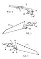
- a shaft (2) formed from pressed metal, such as steel, and having in the centre thereof a yoke (4).
- One end of the shaft (2) is formed integrally with a depending retaining member, here a blade mount (6).
- the blade mount (6) comprises a restraining means, here two arms (8) which depend from the shaft (2).
- the blade mount further includes a pin (10) which will be described in more detail below.
- the shaft (2) is arranged to drive a saw blade (12) presented thereto and which is mounted on the blade mount (6).
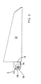
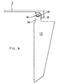
- the saw blade (12) has a shank (14) which has formed therein a hole (16) (seen more clearly in Figures 5, 8 and 9) for mounting the blade (12) on a lug (18) of the pin (10).
- the saw blade (12) includes a shank in this, preferred, embodiment, the shank may be formed integrally with the body portion, as discussed below and with reference to Figure 14(b).
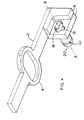
- the pin (10) comprises a head (20) formed on one side of the blade mount (6) and a lug (18) co-operating with the head (20) formed on the other side of the blade mount (6).
- the shape of the lug (18) is the same as that of the hole (16) formed in the blade (12). This allows for the blade (12) to be mounted snugly on the lug (18).
- the pin (10) is rotatable about its axis shown as X-X in Figure 4 and it can be seen from this figure that the blade mount (6) has a recess (21) formed therein such that the lug (18) may sit within the recess (21) when it is in one of two positions. Because the pin (10) is rotatable about the axis X-X, then whenever the lug (18) is aligned with the recess (21) (in either of two positions 180° apart) then it will fit within the recess (21). In any other position, the lug (18) cannot sit within the recess (21).
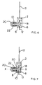
- the head (20) of the pin (10) is spring biased. In this manner, therefore, whenever the lug (18) is aligned with the recess (21) it "pops" into the recess and is held therein until the user exerts sufficient force against the head (20) against the action of the spring (described later below) to force the lug (18) out of the recess (21) and therefore allow the pin (10) to be rotated about the axis X-X.
- each of the arms (8) is arranged to flank the shank (14) of the blade (12) to prevent the blade (12) from becoming detached from the blade mount (6). This is because the arms (8) prevent any movement of the blade (12) in a direction perpendicular to the direction of reciprocation of the shaft (2).
- the pin (10) is spring biased, and in the case of Figure 6, it can be seen that the head (20) of the pin (10) has not been depressed and therefore under the action of the spring (22), the head (20) is forced to the left of Figure 6 therefore allowing the lug (18) to sit within the recess (21). This does, of course, presuppose that the lug (18) is aligned with the recess (21) as has been described here above. Assuming this to be the case, then the blade will be locked in this position. Rotation of the pin and therefore the lug (18) are not possible because the lug (18) is located within the housing (20).
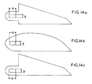
- the mounting hole (6) extends in two, generally perpendicular directions. In the figures, these directions have been indicated by the axes marked "x" and "y". It can be seen that the length of extent of one of these axes, here "x”, is greater than the length of extent of the other of these axes, here "y”. This is permit rigid (that is non-moveable) mounting of the blade (12) on the lug (18).
- the mounting hole (6) it is preferable for the mounting hole (6) to be formed within the body of the saw blade (12) such that the hole (6) does not touch any peripheral surface of the blade (12).
- Figure 14(a) illustrates the case where the hole (6) is formed as a rectangle; Figure 14(b) that where the hole (6) is formed as an ellipse; and Figure 14(c) that where the hole (6) is formed as an oval. These variants all share the common property of having a length of extent in one dimension greater than that in another, orthogonal, direction.
- the power tool is a power saw.
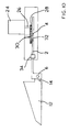
- An electric motor (24) is operable in conventional manner to drive a motor spindle (26) coupled to a drive wheel (28).
- the teeth of the drive wheel (28) mesh with the teeth of a gear wheel (30) having formed thereon an eccentric (32).
- the eccentric (32) must be counter-balanced and those skilled in the art will appreciate this fact.
- the eccentric (32) fits into the yoke (4).
- the motor (24) when the motor (24) is activated, it drives the drive wheel (28) which in turn causes rotation of the gear wheel (30).
- the circular movement of the eccentric (32) sitting in the yoke (4) therefore causes a linear reciprocal motion of the shaft (2) in a right-left-right motion as the drawings are viewed.
- a retaining bar (34) having linear bearings surrounds the shaft (2). This restrains movement of the shaft only in the left-right-left linear direction.
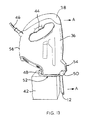
- Figures 12 and 13 two further embodiments of the present invention are now described. It can be seen by comparing these two figures, that the power tools shown therein share the same body (36). However, the tools shown in Figures 12 and 13 each are used for a different purpose and operate in different modes, as will be described here below. It should be understood that, for the purposes of Figures 12 and 13, the internal mechanism as shown in Figures 10 and 11 is incorporated therein. However, because Figures 12 and 13 show the tool from the outside, then the internal mechanisms cannot be seen.
- the tool is used as a so-called panel saw.
- Panel saws are generally used for sawing large pieces of wood and the like in the form of blocks such as logs.
- the saw needs to be lightweight but also it has been found that, when the saw is being driven by the motor (24), conventional reciprocating action will prevent manually using the tool with ease, because of the combination of the frequency of reciprocation of the saw blade (12) and the length of each reciprocal stroke.
- the same body (36) is used with a different saw blade (12).
- the saw blade (12) is that found on conventional "jigsaws".
- Jigsaws are tools which are used with relatively small saw blades and are used for cutting accurate shapes in a workpiece.
- jigsaws are held relative to the workpiece in a different attitude to panel saws. This can be seen by reference to the difference in attitude between Figure 12 and 13.
- the body (36) can be seen resting on a block (42) which represents a workpiece. In use of the jigsaw, the body (36) would be held on the block (42) in the attitude shown in Figure 13.
- the handle (38) is now positioned relative to the workpiece (42) such that the body (36) may easily be used as a jigsaw.
- a user exerts a force via the handle (38) in the direction of the large arrow marked "A". This is so that the blade (12) is driven also in the direction of the arrow "A" to cut through the workpiece.
- the handle (38) is positioned adjacent a trigger (44) which trigger (44) is operable by user when the handle (38) is gripped.
- the trigger (44) is formed integrally with the handle (38). This need not necessarily be the case, and the trigger may be formed separately or indeed on another part of the body (36).
- the handle (38) is accessible from one of two sides, depending on whether the tool is to be used as a panel saw or a jigsaw. It is envisaged that the present invention is of scope to allow more than two sides of the handle (38) to be used depending on the purpose to which the tool is being put.
- the body (36) also includes a pivotable sole plate (48).
- the sole plate (48) is pivotable about pivot point (50).
- the pivot point (50) includes a means (not shown) for allowing the sole plate (48) to be held at any one of a desired position around the range of possible pivotable positions about the point (50).
- the sole plate (48) is tucked underneath the body (36).
- the sole plate (48) is pivoted through 270° so as to act as the guide sole plate for a conventional jigsaw. In this mode, the blade (12) passes through the sole plate (48) when used in its jigsaw mode.
- jigsaws use a sole plate (48) to act as a guide when cutting a workpiece.
- the sole plate (48) includes visual indicia to allow the user to see exactly where the blade (12) will cut the workpiece when viewed from above the body (36).
- the body (36) defines two working surfaces (52 and 54) dependent upon which mode the tool is being used.
- working surface (52) is used for the jigsaw mode of Figure 13
- working surface (54) is used for the panel saw mode of Figure 12.
- the sole plate (48) may be positioned at any suitable angle relevant to the body (36) dependent upon the use to which the tool is being put.
Landscapes
- Engineering & Computer Science (AREA)
- Mechanical Engineering (AREA)
- Sawing (AREA)
- Power Steering Mechanism (AREA)
- Holo Graphy (AREA)
- Gripping Jigs, Holding Jigs, And Positioning Jigs (AREA)
- Shovels (AREA)
Applications Claiming Priority (2)
| Application Number | Priority Date | Filing Date | Title |
|---|---|---|---|
| GB9827943A GB9827943D0 (en) | 1998-12-18 | 1998-12-18 | An arrangement for clamping a saw blade |
| GB9827943 | 1998-12-18 |
Publications (4)
| Publication Number | Publication Date |
|---|---|
| EP1010489A2 true EP1010489A2 (fr) | 2000-06-21 |
| EP1010489A3 EP1010489A3 (fr) | 2000-10-25 |
| EP1010489B1 EP1010489B1 (fr) | 2007-05-23 |
| EP1010489B9 EP1010489B9 (fr) | 2008-02-13 |
Family
ID=10844516
Family Applications (1)
| Application Number | Title | Priority Date | Filing Date |
|---|---|---|---|
| EP19990310262 Expired - Lifetime EP1010489B9 (fr) | 1998-12-18 | 1999-12-20 | Dispositif de serrage de lame de scie |
Country Status (8)
| Country | Link |
|---|---|
| US (1) | US6857348B1 (fr) |
| EP (1) | EP1010489B9 (fr) |
| CN (1) | CN1131757C (fr) |
| AT (1) | ATE362815T1 (fr) |
| AU (1) | AU757123B2 (fr) |
| DE (1) | DE69936127T2 (fr) |
| ES (1) | ES2284239T4 (fr) |
| GB (1) | GB9827943D0 (fr) |
Cited By (2)
| Publication number | Priority date | Publication date | Assignee | Title |
|---|---|---|---|---|
| EP2047933A3 (fr) * | 2007-10-10 | 2010-07-14 | Techtronic Industries Company Limited | Scie disposant d'une lame stockable |
| EP2067557A3 (fr) * | 2007-12-06 | 2011-03-30 | SCHMID & WEZEL GmbH & Co. | Scie pouvant être entraînée de manière motorisée dotée d'une fixation de lame de scie et une lame de scie échangeable, ainsi que lame de scie |
Families Citing this family (12)
| Publication number | Priority date | Publication date | Assignee | Title |
|---|---|---|---|---|
| US8230607B2 (en) | 2008-05-09 | 2012-07-31 | Milwaukee Electric Tool Corporation | Keyless blade clamp for a power tool |
| CN201597020U (zh) * | 2009-07-01 | 2010-10-06 | 蔡吕乾 | 一种摆式工具工作头 |
| US8555516B2 (en) | 2010-03-25 | 2013-10-15 | Black & Decker Inc. | Pivoting blade retainer |
| US20110315413A1 (en) * | 2010-06-25 | 2011-12-29 | Mako Surgical Corp. | Kit-Of Parts for Multi-Functional Tool, Drive Unit, and Operating Members |
| US9321112B2 (en) | 2011-05-18 | 2016-04-26 | Black & Decker Inc. | Power saw tool |
| US9475141B2 (en) | 2011-08-04 | 2016-10-25 | Milwaukee Electric Tool Corporation | Reciprocating saw blade |
| US9156097B2 (en) | 2012-03-20 | 2015-10-13 | Milwaukee Electric Tool Corporation | Reciprocating saw blade clamp |
| USD688543S1 (en) | 2012-03-20 | 2013-08-27 | Milwaukee Electric Tool Corporation | Saw blade |
| USD687275S1 (en) | 2012-03-20 | 2013-08-06 | Milwaukee Electric Tool Corporation | Saw blade |
| US9559628B2 (en) | 2013-10-25 | 2017-01-31 | Black & Decker Inc. | Handheld power tool with compact AC switch |
| USD729600S1 (en) | 2014-05-06 | 2015-05-19 | Milwaukee Electric Tool Corporation | Saw blade |
| US10342553B2 (en) | 2015-01-21 | 2019-07-09 | Stryker European Holdings I, Llc | Surgical sagittal saw and complementary blade with features that fixedly hold the blade static to the saw |
Family Cites Families (21)
| Publication number | Priority date | Publication date | Assignee | Title |
|---|---|---|---|---|
| BE440688A (fr) | ||||
| US1266832A (en) * | 1917-12-04 | 1918-05-21 | John M Lee | Detachable-handle construction. |
| US2282902A (en) | 1940-01-25 | 1942-05-12 | Sultan Max | Hacksaw |
| US2945298A (en) * | 1955-08-03 | 1960-07-19 | Lenslite Co Inc | Power operated cutting device |
| US3823473A (en) * | 1970-11-09 | 1974-07-16 | S Hoffman | Blade attachment means for saber saw assembly |
| US3901117A (en) | 1970-11-09 | 1975-08-26 | Simon J Hoffman | Saber saw and blade therefor |
| JPS5396628A (en) * | 1977-02-02 | 1978-08-24 | Toshiba Corp | H-l switching system of signal system |
| FR2510463A1 (fr) | 1981-07-31 | 1983-02-04 | Peugeot Aciers Et Outillage | Machine-outil a main pour outil de decoupage oscillant |
| GB8523425D0 (en) * | 1985-09-23 | 1985-10-30 | Black & Decker Inc | Power tools |
| US5092045A (en) * | 1990-02-16 | 1992-03-03 | Boyd Jr Francis M | Lock block for a multipled-positioned knife or device |
| US5079844A (en) * | 1990-11-13 | 1992-01-14 | Milwaukee Electric Tool Corporation | Counterbalanced reciprocating mechanism |
| US5263972A (en) * | 1991-01-11 | 1993-11-23 | Stryker Corporation | Surgical handpiece chuck and blade |
| US5340129A (en) * | 1993-01-21 | 1994-08-23 | Minnesota Mining And Manufacturing Company | Saw blade retention system |
| US6237231B1 (en) * | 1994-11-29 | 2001-05-29 | Milwaukee Electric Tool Corporation | Keyless clamp assembly for reciprocating tool |
| DE19614832C1 (de) * | 1996-04-15 | 1997-04-17 | Aesculap Ag | Säge für chirurgische Zwecke |
| US5722168A (en) * | 1996-07-29 | 1998-03-03 | Huang; Jung Hua | Saw blade securing mechanism |
| US5832611A (en) * | 1996-08-07 | 1998-11-10 | Schmitz; Jeffrey F. | Variable angle reciprocating tool |
| EP0882537B1 (fr) * | 1997-06-05 | 2003-09-03 | Black & Decker Inc. | Scie alternative avec dispositif de serrage permettant le blocage de la lame de scie en plusieurs positions angulaires |
| US6105260A (en) * | 1998-01-23 | 2000-08-22 | Alterra Holdings Corporation | Universal saw adapter |
| US5930902A (en) * | 1998-06-11 | 1999-08-03 | Hsu; An-Sun | Saw with a removable saw blade |
| US5979065A (en) * | 1998-06-11 | 1999-11-09 | Hsu; An-Sun | Handle assembly for a foldable saw |
-
1998
- 1998-12-18 GB GB9827943A patent/GB9827943D0/en not_active Ceased
-
1999
- 1999-12-15 US US09/461,265 patent/US6857348B1/en not_active Expired - Fee Related
- 1999-12-16 AU AU65282/99A patent/AU757123B2/en not_active Ceased
- 1999-12-17 CN CN99126411A patent/CN1131757C/zh not_active Expired - Fee Related
- 1999-12-20 AT AT99310262T patent/ATE362815T1/de not_active IP Right Cessation
- 1999-12-20 EP EP19990310262 patent/EP1010489B9/fr not_active Expired - Lifetime
- 1999-12-20 DE DE1999636127 patent/DE69936127T2/de not_active Expired - Lifetime
- 1999-12-20 ES ES99310262T patent/ES2284239T4/es not_active Expired - Lifetime
Cited By (2)
| Publication number | Priority date | Publication date | Assignee | Title |
|---|---|---|---|---|
| EP2047933A3 (fr) * | 2007-10-10 | 2010-07-14 | Techtronic Industries Company Limited | Scie disposant d'une lame stockable |
| EP2067557A3 (fr) * | 2007-12-06 | 2011-03-30 | SCHMID & WEZEL GmbH & Co. | Scie pouvant être entraînée de manière motorisée dotée d'une fixation de lame de scie et une lame de scie échangeable, ainsi que lame de scie |
Also Published As
| Publication number | Publication date |
|---|---|
| ES2284239T3 (es) | 2007-11-01 |
| US6857348B1 (en) | 2005-02-22 |
| AU6528299A (en) | 2000-06-22 |
| AU757123B2 (en) | 2003-02-06 |
| CN1261021A (zh) | 2000-07-26 |
| EP1010489B1 (fr) | 2007-05-23 |
| ATE362815T1 (de) | 2007-06-15 |
| DE69936127D1 (de) | 2007-07-05 |
| EP1010489A3 (fr) | 2000-10-25 |
| EP1010489B9 (fr) | 2008-02-13 |
| ES2284239T4 (es) | 2008-05-01 |
| CN1131757C (zh) | 2003-12-24 |
| DE69936127T2 (de) | 2008-01-17 |
| GB9827943D0 (en) | 1999-02-10 |
Similar Documents
| Publication | Publication Date | Title |
|---|---|---|
| US6857348B1 (en) | Arrangement for clamping a saw blade | |
| EP2694260B1 (fr) | Scie sauteuse | |
| US7254892B2 (en) | Support mechanism for a reciprocating tool | |
| US6694625B1 (en) | Power tool | |
| CN101642834B (zh) | 手持式往复锯及其操作方法 | |
| JPH09109102A (ja) | 動力工具の鋸刃固定装置 | |
| EP1297932A1 (fr) | Outil motorisé | |
| CN201244699Y (zh) | 手持式往复锯 | |
| US6357123B1 (en) | Jigsaw apparatus | |
| JPS6144526A (ja) | 可搬式回しびき鋸 | |
| US7024779B1 (en) | Power saw | |
| US11311952B2 (en) | Reciprocating saw | |
| JP2018034251A (ja) | バンドソー | |
| AU2002100583B4 (en) | Power Tool | |
| CN218926426U (zh) | 一种往复锯 | |
| CN1116970C (zh) | 手持式线锯机具 | |
| EP1514655B1 (fr) | Ensemble formant une semelle pour un outil à mouvement alternatif | |
| WO2014159674A1 (fr) | Outil oscillant | |
| JPH06206203A (ja) | 切断方法及びその工具 | |
| JPH06155404A (ja) | 切断工具 | |
| GB2202025A (en) | Oscillating right angle drive system | |
| KR20010056129A (ko) | 기어식 휴대용 수동식 쇠톱절단기 | |
| JPH0829504B2 (ja) | 振動工具 | |
| CA2011742A1 (fr) | Scie a chantourner fonctionnant sur batterie | |
| JPH10235605A (ja) | 加工機のアタッチメント |
Legal Events
| Date | Code | Title | Description |
|---|---|---|---|
| PUAI | Public reference made under article 153(3) epc to a published international application that has entered the european phase |
Free format text: ORIGINAL CODE: 0009012 |
|
| 17P | Request for examination filed |
Effective date: 20000422 |
|
| AK | Designated contracting states |
Kind code of ref document: A2 Designated state(s): AT BE CH CY DE DK ES FI FR GB GR IE IT LI LU MC NL PT SE |
|
| AX | Request for extension of the european patent |
Free format text: AL;LT;LV;MK;RO;SI |
|
| PUAL | Search report despatched |
Free format text: ORIGINAL CODE: 0009013 |
|
| AK | Designated contracting states |
Kind code of ref document: A3 Designated state(s): AT BE CH CY DE DK ES FI FR GB GR IE IT LI LU MC NL PT SE |
|
| AX | Request for extension of the european patent |
Free format text: AL;LT;LV;MK;RO;SI |
|
| AKX | Designation fees paid |
Free format text: AT BE CH CY DE DK ES FI FR GB GR IE IT LI LU MC NL PT SE |
|
| 17Q | First examination report despatched |
Effective date: 20011107 |
|
| 17Q | First examination report despatched |
Effective date: 20011107 |
|
| GRAP | Despatch of communication of intention to grant a patent |
Free format text: ORIGINAL CODE: EPIDOSNIGR1 |
|
| GRAS | Grant fee paid |
Free format text: ORIGINAL CODE: EPIDOSNIGR3 |
|
| GRAA | (expected) grant |
Free format text: ORIGINAL CODE: 0009210 |
|
| AK | Designated contracting states |
Kind code of ref document: B1 Designated state(s): AT BE CH CY DE DK ES FI FR GB GR IE IT LI LU MC NL PT SE |
|
| PG25 | Lapsed in a contracting state [announced via postgrant information from national office to epo] |
Ref country code: LI Free format text: LAPSE BECAUSE OF FAILURE TO SUBMIT A TRANSLATION OF THE DESCRIPTION OR TO PAY THE FEE WITHIN THE PRESCRIBED TIME-LIMIT Effective date: 20070523 Ref country code: FI Free format text: LAPSE BECAUSE OF FAILURE TO SUBMIT A TRANSLATION OF THE DESCRIPTION OR TO PAY THE FEE WITHIN THE PRESCRIBED TIME-LIMIT Effective date: 20070523 Ref country code: CH Free format text: LAPSE BECAUSE OF FAILURE TO SUBMIT A TRANSLATION OF THE DESCRIPTION OR TO PAY THE FEE WITHIN THE PRESCRIBED TIME-LIMIT Effective date: 20070523 |
|
| REG | Reference to a national code |
Ref country code: GB Ref legal event code: FG4D |
|
| REG | Reference to a national code |
Ref country code: CH Ref legal event code: EP |
|
| REG | Reference to a national code |
Ref country code: IE Ref legal event code: FG4D |
|
| REF | Corresponds to: |
Ref document number: 69936127 Country of ref document: DE Date of ref document: 20070705 Kind code of ref document: P |
|
| PG25 | Lapsed in a contracting state [announced via postgrant information from national office to epo] |
Ref country code: SE Free format text: LAPSE BECAUSE OF FAILURE TO SUBMIT A TRANSLATION OF THE DESCRIPTION OR TO PAY THE FEE WITHIN THE PRESCRIBED TIME-LIMIT Effective date: 20070823 |
|
| REG | Reference to a national code |
Ref country code: ES Ref legal event code: FG2A Ref document number: 2284239 Country of ref document: ES Kind code of ref document: T3 |
|
| ET | Fr: translation filed | ||
| PG25 | Lapsed in a contracting state [announced via postgrant information from national office to epo] |
Ref country code: AT Free format text: LAPSE BECAUSE OF FAILURE TO SUBMIT A TRANSLATION OF THE DESCRIPTION OR TO PAY THE FEE WITHIN THE PRESCRIBED TIME-LIMIT Effective date: 20070523 |
|
| REG | Reference to a national code |
Ref country code: CH Ref legal event code: PL |
|
| PG25 | Lapsed in a contracting state [announced via postgrant information from national office to epo] |
Ref country code: BE Free format text: LAPSE BECAUSE OF FAILURE TO SUBMIT A TRANSLATION OF THE DESCRIPTION OR TO PAY THE FEE WITHIN THE PRESCRIBED TIME-LIMIT Effective date: 20070523 |
|
| PG25 | Lapsed in a contracting state [announced via postgrant information from national office to epo] |
Ref country code: PT Free format text: LAPSE BECAUSE OF FAILURE TO SUBMIT A TRANSLATION OF THE DESCRIPTION OR TO PAY THE FEE WITHIN THE PRESCRIBED TIME-LIMIT Effective date: 20071023 Ref country code: DK Free format text: LAPSE BECAUSE OF FAILURE TO SUBMIT A TRANSLATION OF THE DESCRIPTION OR TO PAY THE FEE WITHIN THE PRESCRIBED TIME-LIMIT Effective date: 20070523 |
|
| PLBE | No opposition filed within time limit |
Free format text: ORIGINAL CODE: 0009261 |
|
| STAA | Information on the status of an ep patent application or granted ep patent |
Free format text: STATUS: NO OPPOSITION FILED WITHIN TIME LIMIT |
|
| 26N | No opposition filed |
Effective date: 20080226 |
|
| PG25 | Lapsed in a contracting state [announced via postgrant information from national office to epo] |
Ref country code: GR Free format text: LAPSE BECAUSE OF FAILURE TO SUBMIT A TRANSLATION OF THE DESCRIPTION OR TO PAY THE FEE WITHIN THE PRESCRIBED TIME-LIMIT Effective date: 20070824 |
|
| PG25 | Lapsed in a contracting state [announced via postgrant information from national office to epo] |
Ref country code: MC Free format text: LAPSE BECAUSE OF NON-PAYMENT OF DUE FEES Effective date: 20071231 |
|
| PG25 | Lapsed in a contracting state [announced via postgrant information from national office to epo] |
Ref country code: IE Free format text: LAPSE BECAUSE OF NON-PAYMENT OF DUE FEES Effective date: 20071220 |
|
| PGFP | Annual fee paid to national office [announced via postgrant information from national office to epo] |
Ref country code: NL Payment date: 20081223 Year of fee payment: 10 |
|
| PGFP | Annual fee paid to national office [announced via postgrant information from national office to epo] |
Ref country code: ES Payment date: 20081226 Year of fee payment: 10 |
|
| PG25 | Lapsed in a contracting state [announced via postgrant information from national office to epo] |
Ref country code: CY Free format text: LAPSE BECAUSE OF FAILURE TO SUBMIT A TRANSLATION OF THE DESCRIPTION OR TO PAY THE FEE WITHIN THE PRESCRIBED TIME-LIMIT Effective date: 20070523 |
|
| PG25 | Lapsed in a contracting state [announced via postgrant information from national office to epo] |
Ref country code: LU Free format text: LAPSE BECAUSE OF NON-PAYMENT OF DUE FEES Effective date: 20071220 |
|
| PGFP | Annual fee paid to national office [announced via postgrant information from national office to epo] |
Ref country code: IT Payment date: 20081223 Year of fee payment: 10 |
|
| PGFP | Annual fee paid to national office [announced via postgrant information from national office to epo] |
Ref country code: GB Payment date: 20091229 Year of fee payment: 11 Ref country code: FR Payment date: 20100106 Year of fee payment: 11 |
|
| PGFP | Annual fee paid to national office [announced via postgrant information from national office to epo] |
Ref country code: DE Payment date: 20091230 Year of fee payment: 11 |
|
| REG | Reference to a national code |
Ref country code: NL Ref legal event code: V1 Effective date: 20100701 |
|
| PG25 | Lapsed in a contracting state [announced via postgrant information from national office to epo] |
Ref country code: NL Free format text: LAPSE BECAUSE OF NON-PAYMENT OF DUE FEES Effective date: 20100701 |
|
| REG | Reference to a national code |
Ref country code: ES Ref legal event code: FD2A Effective date: 20110304 |
|
| PG25 | Lapsed in a contracting state [announced via postgrant information from national office to epo] |
Ref country code: IT Free format text: LAPSE BECAUSE OF NON-PAYMENT OF DUE FEES Effective date: 20091220 |
|
| PG25 | Lapsed in a contracting state [announced via postgrant information from national office to epo] |
Ref country code: ES Free format text: LAPSE BECAUSE OF NON-PAYMENT OF DUE FEES Effective date: 20110303 |
|
| GBPC | Gb: european patent ceased through non-payment of renewal fee |
Effective date: 20101220 |
|
| REG | Reference to a national code |
Ref country code: FR Ref legal event code: ST Effective date: 20110831 |
|
| PG25 | Lapsed in a contracting state [announced via postgrant information from national office to epo] |
Ref country code: ES Free format text: LAPSE BECAUSE OF NON-PAYMENT OF DUE FEES Effective date: 20091221 |
|
| PG25 | Lapsed in a contracting state [announced via postgrant information from national office to epo] |
Ref country code: FR Free format text: LAPSE BECAUSE OF NON-PAYMENT OF DUE FEES Effective date: 20110103 |
|
| REG | Reference to a national code |
Ref country code: DE Ref legal event code: R119 Ref document number: 69936127 Country of ref document: DE Effective date: 20110701 |
|
| PG25 | Lapsed in a contracting state [announced via postgrant information from national office to epo] |
Ref country code: DE Free format text: LAPSE BECAUSE OF NON-PAYMENT OF DUE FEES Effective date: 20110701 Ref country code: GB Free format text: LAPSE BECAUSE OF NON-PAYMENT OF DUE FEES Effective date: 20101220 |