EP1010577A2 - Méthode de correction d'un signal représentant la courbure de la route sur lequel le véhicule se déplace - Google Patents
Méthode de correction d'un signal représentant la courbure de la route sur lequel le véhicule se déplace Download PDFInfo
- Publication number
- EP1010577A2 EP1010577A2 EP99122368A EP99122368A EP1010577A2 EP 1010577 A2 EP1010577 A2 EP 1010577A2 EP 99122368 A EP99122368 A EP 99122368A EP 99122368 A EP99122368 A EP 99122368A EP 1010577 A2 EP1010577 A2 EP 1010577A2
- Authority
- EP
- European Patent Office
- Prior art keywords
- expected
- signal
- parameter
- determined
- vehicle
- Prior art date
- Legal status (The legal status is an assumption and is not a legal conclusion. Google has not performed a legal analysis and makes no representation as to the accuracy of the status listed.)
- Withdrawn
Links
Images

Classifications
-
- G—PHYSICS
- G01—MEASURING; TESTING
- G01S—RADIO DIRECTION-FINDING; RADIO NAVIGATION; DETERMINING DISTANCE OR VELOCITY BY USE OF RADIO WAVES; LOCATING OR PRESENCE-DETECTING BY USE OF THE REFLECTION OR RERADIATION OF RADIO WAVES; ANALOGOUS ARRANGEMENTS USING OTHER WAVES
- G01S13/00—Systems using the reflection or reradiation of radio waves, e.g. radar systems; Analogous systems using reflection or reradiation of waves whose nature or wavelength is irrelevant or unspecified
- G01S13/88—Radar or analogous systems specially adapted for specific applications
- G01S13/93—Radar or analogous systems specially adapted for specific applications for anti-collision purposes
- G01S13/931—Radar or analogous systems specially adapted for specific applications for anti-collision purposes of land vehicles
-
- B—PERFORMING OPERATIONS; TRANSPORTING
- B62—LAND VEHICLES FOR TRAVELLING OTHERWISE THAN ON RAILS
- B62D—MOTOR VEHICLES; TRAILERS
- B62D15/00—Steering not otherwise provided for
- B62D15/02—Steering position indicators ; Steering position determination; Steering aids
- B62D15/021—Determination of steering angle
- B62D15/0245—Means or methods for determination of the central position of the steering system, e.g. straight ahead position
-
- G—PHYSICS
- G01—MEASURING; TESTING
- G01S—RADIO DIRECTION-FINDING; RADIO NAVIGATION; DETERMINING DISTANCE OR VELOCITY BY USE OF RADIO WAVES; LOCATING OR PRESENCE-DETECTING BY USE OF THE REFLECTION OR RERADIATION OF RADIO WAVES; ANALOGOUS ARRANGEMENTS USING OTHER WAVES
- G01S13/00—Systems using the reflection or reradiation of radio waves, e.g. radar systems; Analogous systems using reflection or reradiation of waves whose nature or wavelength is irrelevant or unspecified
- G01S13/02—Systems using reflection of radio waves, e.g. primary radar systems; Analogous systems
- G01S13/50—Systems of measurement based on relative movement of target
- G01S13/58—Velocity or trajectory determination systems; Sense-of-movement determination systems
-
- B—PERFORMING OPERATIONS; TRANSPORTING
- B60—VEHICLES IN GENERAL
- B60K—ARRANGEMENT OR MOUNTING OF PROPULSION UNITS OR OF TRANSMISSIONS IN VEHICLES; ARRANGEMENT OR MOUNTING OF PLURAL DIVERSE PRIME-MOVERS IN VEHICLES; AUXILIARY DRIVES FOR VEHICLES; INSTRUMENTATION OR DASHBOARDS FOR VEHICLES; ARRANGEMENTS IN CONNECTION WITH COOLING, AIR INTAKE, GAS EXHAUST OR FUEL SUPPLY OF PROPULSION UNITS IN VEHICLES
- B60K31/00—Vehicle fittings, acting on a single sub-unit only, for automatically controlling vehicle speed, i.e. preventing speed from exceeding an arbitrarily established velocity or maintaining speed at a particular velocity, as selected by the vehicle operator
- B60K31/0066—Vehicle fittings, acting on a single sub-unit only, for automatically controlling vehicle speed, i.e. preventing speed from exceeding an arbitrarily established velocity or maintaining speed at a particular velocity, as selected by the vehicle operator responsive to vehicle path curvature
-
- G—PHYSICS
- G01—MEASURING; TESTING
- G01S—RADIO DIRECTION-FINDING; RADIO NAVIGATION; DETERMINING DISTANCE OR VELOCITY BY USE OF RADIO WAVES; LOCATING OR PRESENCE-DETECTING BY USE OF THE REFLECTION OR RERADIATION OF RADIO WAVES; ANALOGOUS ARRANGEMENTS USING OTHER WAVES
- G01S13/00—Systems using the reflection or reradiation of radio waves, e.g. radar systems; Analogous systems using reflection or reradiation of waves whose nature or wavelength is irrelevant or unspecified
- G01S13/88—Radar or analogous systems specially adapted for specific applications
- G01S13/93—Radar or analogous systems specially adapted for specific applications for anti-collision purposes
- G01S13/931—Radar or analogous systems specially adapted for specific applications for anti-collision purposes of land vehicles
- G01S2013/932—Radar or analogous systems specially adapted for specific applications for anti-collision purposes of land vehicles using own vehicle data, e.g. ground speed, steering wheel direction
-
- G—PHYSICS
- G01—MEASURING; TESTING
- G01S—RADIO DIRECTION-FINDING; RADIO NAVIGATION; DETERMINING DISTANCE OR VELOCITY BY USE OF RADIO WAVES; LOCATING OR PRESENCE-DETECTING BY USE OF THE REFLECTION OR RERADIATION OF RADIO WAVES; ANALOGOUS ARRANGEMENTS USING OTHER WAVES
- G01S13/00—Systems using the reflection or reradiation of radio waves, e.g. radar systems; Analogous systems using reflection or reradiation of waves whose nature or wavelength is irrelevant or unspecified
- G01S13/88—Radar or analogous systems specially adapted for specific applications
- G01S13/93—Radar or analogous systems specially adapted for specific applications for anti-collision purposes
- G01S13/931—Radar or analogous systems specially adapted for specific applications for anti-collision purposes of land vehicles
- G01S2013/9321—Velocity regulation, e.g. cruise control
Definitions
- the present invention relates to a method for correcting a signal of at least one Sensor, on the basis of which a path curve can be determined on which the vehicle is moving, according to the preamble of claim 1.
- the vehicle has a device with which the surroundings of the vehicle can be recognized and by correcting the Signal of the at least one sensor takes place by the at least one point in time at least one further point in time expected object location one recognized as standing Object is determined based on the vehicle speed and the signal of the at least a sensor and by at least one further point in time the object location of the as standing recognized object is recorded, with a correction of the signal of the at least one sensor based on the deviation of the expected object location from the recorded location takes place.
- This method advantageously allows static deviations, for example due to an adjustment of the track of the vehicle can be compensated.
- this object location can be compared with the one measured at the further point in time, i.e. recorded object location are compared.
- the device recognizes the environment by means of Radar beams.
- Such devices are known and are already being tested. By means of such The environment can be set up well with regard to moving and standing objects detect. In addition, such devices are preferred in the beginning described systems used in which a speed control and / or Steering control of the vehicle should take place without intervention by the driver. The The device can then be used both for the control itself and for the adjustment of the sensor or of sensors are used, from whose signal the trajectory of the vehicle is determined becomes.
- At least one parameter of a trajectory for the Deviation of the curve of the expected object locations from the recorded object locations certainly.
- An offset for the signal of the at least one sensor can be determined.
- a set of expected and recorded Object locations which determines at least one parameter. Furthermore, several sentences certain parameters averaged from expected and recorded object locations.
- This weighting enables an assessment to be made of how reliable that is for a sentence at least one parameter determined from expected and recorded object locations. If based on the value of the determined at least one parameter this would result in a correspondingly large correction, for example with low weighting are taken into account in order first to wait whether this value of the at least one parameter for further sets of expected and recorded Object locations confirmed. In this way, errors can advantageously be compensated for if at time successive measurements of identified object locations are assigned to a specific object for which object locations have already been determined, although there may be several Objects that are comparatively close together and in individual measurements may be covered so that the assigned object locations are not actually the same Corresponded to the object.
- the weighting can be carried out, for example, so that the at least one Parameter with decreasing weighting is taken into account when averaging Parameter exceeds the certain limit.
- the parameter can also be disregarded stay if it exceeds the certain limit. It is also possible to use one to provide a continuously differentiable course of a weighting factor, this factor decreases depending on the value of the parameter in relation to a certain limit.
- an error which is the deviation of the trajectory from the expected and / or recorded object locations to that calculated with the at least one parameter Path curve gives the at least one parameter with a weighting in the averaging is taken into account.
- the weighting can be carried out, for example, so that the at least one Parameter with decreasing weighting is taken into account when averaging Error ⁇ y exceeds the limit.
- the parameter can also be disregarded if the error ⁇ y exceeds the limit. It is also possible to have a steady provide a differentiable course of a weighting factor, this factor decreases depending on the value of the error ⁇ y in relation to a limit.
- the at least one parameter is within a Set determined only when the maximum amount of change in the signal of the at least one sensor during this set is less than a certain threshold.
- the determined threshold value can be approximately 5 ° if the signal of the at least one sensor is the steering angle.
- the at least one parameter is within a Set determined only if the maximum amount of the signal of the at least one Sensor during this set is less than a certain limit.
- the determination of the parameters is flawed. It is therefore advantageous the determination of the at least one parameter is not carried out if, for example the signal of the at least one sensor is the toe angle of the vehicle and its amount is greater than a certain limit.
- the specific limit can be approximately 7.5 °.
- the curve curvature error when cornering tightly caused by a track angle error to be smaller than the measuring accuracy of the sensor, with which the objects are captured. In this case, there is no offset error detection more is possible.
- the signal evaluation is simplified because driving dynamics influences such as for example the self-steering gradient in these driving conditions in driving dynamics Equations can be neglected.
- the signal of the at least one sensor represents the toe angle of the vehicle. This is derived from the measured steering angle, the correction is made by adding an offset.
- the steering angle is a comparatively easily measurable quantity. So it can be from this Measured variable the signal are derived, which represents the toe angle of the vehicle.
- a warning signal is issued when the amount of determined value of the offset exceeds a certain threshold.
- the distance to the object recognized as standing greater than a certain minimum distance.
- the distance to the object recognized as standing less than a certain maximum distance.
- the minimum distance a value of about 15m has proven to be suitable for the Maximum distance a value of about 120m. At distances above the The maximum distance will be the changes in the angles at which this was recognized as standing Object is observed too low. If the distance is too short (below the Minimum distance) the change of these angles is too large. It has been particularly advantageous prove to be the distance range between 30m and 70m.
- the trajectory is a minimum number of expected and recorded object locations or a set of expected and Object locations consists of a minimum number of expected and recorded object locations.
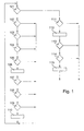
- a correction value is first calculated in steps 101 to 110, which in steps 111 to 115 with other determined correction values, statistically averaged and is processed further.
- step 101 it is checked in step 101 whether a set of independent objects with the in the history of expected and recorded object locations (positions) has been fully evaluated ( Figure 3). If these objects, that is, which are made up of the individual sets of object tracks resulting from recorded object locations, not yet have been completely evaluated, a transition is made to step 102, in which it is checked whether the processed object has been recognized as standing. The one on it The following steps 103 to 110 are then carried out for each object recognized as standing associated history (expected and recorded object locations of an object previous measurements) processed.
- step 103 in which it is checked whether this is Object is at a suitable distance in front of the vehicle.
- This distance can for example between 30m and 70m. If this makes the number of objects too strong this distance range can be extended to 15m to 120m, for example become. The approximated distance must therefore be within a certain maximum Distance and are outside a certain minimum distance.
- step 104 If the object is in a corresponding distance range in front of the vehicle there is a transition to step 104, in which it is checked whether the measured Steering angle is smaller than a predetermined maximum value, which is, for example, 7.5 ° can.
- a predetermined maximum value which is, for example, 7.5 ° can.
- the amount of the size to be corrected while capturing the expected and recorded object locations of a set of expected and recorded object locations should be less than a certain limit.
- step 105 in which it is checked whether the Steering angle during the determination of the recorded and the expected object locations a set of expected and recorded object locations by more than a certain one Amount, for example 5 ° changed.
- the amount of change in the size to be corrected during the acquisition of the expected and recorded object locations of a set of expected and recorded object locations should therefore be smaller than a specific one Limit.
- step 106 it is determined from the deviation of the earlier for the current time expected track location from the recorded track location the track angle deviation calculated. At the same time, using the vehicle speed and the measured Track angle expected object locations are calculated for future times. The calculation of the Track angle deviation can also be done by collecting the data of a set and be evaluated using the least squares method.
- FIG. 2 shows a basic illustration of the trajectory curves of the vehicle 205 for determining the parameter or parameters.
- the correction in step 106 when the steering angle is measured is described below. With objects recognized as standing, errors in the steering angle can be determined and corrected by comparing the recorded object tracks with the current steering angle. For this purpose, a difference track f Dif 203 can be formed from the recorded (real) object track f R 201 and the expected object track f E 202, from the curvature of which the current steering angle deviation can be determined.
- the recorded object track f R 201 consists of a number of measured values for the distance x i and the 2blage y i .
- f E (X n, E ): y n, E a 2, E * (x n, E ) 2nd + a 0, E
- a 0, E must be determined using the previous reference point.
- a 0, E y n-1, E - a 2, E * (x n-1, E ) 2nd
- y n, E a 2, E * (x n, E ) 2nd + y n-1, E - a 2, E * (x n-1, E ) 2nd respectively.
- y n, E a 2, E * ((x n, E ) 2nd - (x n-1, E ) 2nd ) + y n-1E .
- the y values result from the difference between the two tracks f R and f E : y i, dif - y i, r - y i, E .
- the parameter a 0 only shows the distance of the trajectory from the vehicle's longitudinal axis (see Figure 2).
- the linear term a 1 is 0 under normal driving conditions, otherwise the vehicle would drift.
- the parameters are determined in such a way that the object locations (the value pairs x i, Diff and y i, Diff ) are approximated as optimally as possible to the trajectory resulting from the parameters.
- a mean error ⁇ y can also be determined in the approximation.
- the mistake represents the mean deviation of the value pairs from the approximated trajectory in y direction.
- the mean square error is expediently calculated. Should the If the calculation effort is too high, the mean weighted error can also be determined become.
- the curvature a 2 of the polynomial can now be used to correct the signal of the at least one sensor.
- the curvature then corresponds to the curvature offset with which the signal or the curvature derived therefrom is afflicted.
- step 107 it is checked whether a minimum number of value pairs is included Object locations used for approximation, this is equivalent to one Check that the approximated distance has a minimum length.
- the error ⁇ y can also be evaluated in a step 108.
- the limit values of the error evaluation must be adapted.
- the error states how well the trajectory could be adapted to the value pairs.
- a large error means that the specified parameters, for example a 2 and a 0, are also highly error-prone.
- step 109 checks whether the specific parameter or parameters does not exceed or fall below certain maximum values and minimum values. As a result, outliers can advantageously be identified. With the above polynomial, a 2 and a 0 are checked here.
- the parameters checked in steps 108 and 109 can be exceeded if the Limit values either mean that the complete measurement of the object is not statistical evaluation is used or possibly only weakly weighted in this flows in.
- step 110 the determined parameters are provided in a distribution for statistical evaluation in step 112 with appropriate weighting.
- step 101 continues with the next detected object, that is to say with the evaluation of the next set of recorded and expected object locations (object tracks). If all sets of recorded and expected object locations, that is to say all object tracks, have been processed, the transition is made to step 111, in which it is checked whether a sufficient number of track angle deviations (a 2 values in the present example) has been calculated. These track angle deviations can have been recorded over a longer period of time.
- the resultant distribution is statistically evaluated in step 112 by averaging the determined track angle deviations or variables derived therefrom.
- the standard deviation can also be determined.
- a spread of the parameters is to be expected. Too large a standard deviation of the parameter (in the example, the averaged a 2 - value) may for example be discarded or offset indication.
- a warning signal is issued if the averaged parameters exceed specified limit values.
- Rotation rates Offset a 2nd * v Own * 360 ° / ⁇ where a 2 corresponds to the differential curvature and v Eigen the vehicle speed at the time of determining the differential curvature.
- step 113 it is checked whether the standard deviation of the mean value formed is less than a predetermined threshold. If this is the case, there is a transition to the Step 114, in which the mean value of the correction value is checked. Exceeds the amount a threshold value, a warning signal can be issued. This correction value is in the Step 115 adds a measured steering angle to the vehicle's toe angle representative signal.
- a is the toe angle of the vehicle representative signal obtained from the measured steering angle.
- corrected all signals of vehicle-related sensors with the inventive method from which a prognosis of the trajectory can be derived on which the vehicle is moving are, for example, the measured toe angle, the measured steering angle, the measured yaw rate around the vehicle vertical axis (yaw rate) or the difference in the measured wheel speed signals from wheels of different Vehicle sides.
- the corresponding sizes can also be one differentiated weighting of the results in subsequent processing steps undergo in order to check the plausibility of the result.
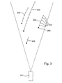
- FIG. 3 shows a vehicle 301.
- the result of this vehicle 301 is Detection angle for the radar sensor shown.
- object tracks objects available, which with 302, 303, 304, 305 are designated.
- the black dots correspond to the respective object locations at the current time.
- the points drawn as a circle are the respective ones Object locations at previous times.
- these are points designated with 307.
Landscapes
- Engineering & Computer Science (AREA)
- Radar, Positioning & Navigation (AREA)
- Remote Sensing (AREA)
- Physics & Mathematics (AREA)
- Computer Networks & Wireless Communication (AREA)
- General Physics & Mathematics (AREA)
- Electromagnetism (AREA)
- Chemical & Material Sciences (AREA)
- Combustion & Propulsion (AREA)
- Transportation (AREA)
- Mechanical Engineering (AREA)
- Traffic Control Systems (AREA)
- Radar Systems Or Details Thereof (AREA)
- Navigation (AREA)
- Control Of Driving Devices And Active Controlling Of Vehicle (AREA)
Applications Claiming Priority (2)
| Application Number | Priority Date | Filing Date | Title |
|---|---|---|---|
| DE19858297A DE19858297A1 (de) | 1998-12-17 | 1998-12-17 | Verfahren zur Korrektur eines Signals wenigstens eines Sensors, aufgrund dessen eine Bahnkurve ermittelbar ist, auf der sich das Fahrzeug bewegt |
| DE19858297 | 1998-12-17 |
Publications (2)
| Publication Number | Publication Date |
|---|---|
| EP1010577A2 true EP1010577A2 (fr) | 2000-06-21 |
| EP1010577A3 EP1010577A3 (fr) | 2003-09-03 |
Family
ID=7891449
Family Applications (1)
| Application Number | Title | Priority Date | Filing Date |
|---|---|---|---|
| EP99122368A Withdrawn EP1010577A3 (fr) | 1998-12-17 | 1999-11-10 | Méthode de correction d'un signal représentant la courbure de la route sur lequel le véhicule se déplace |
Country Status (4)
| Country | Link |
|---|---|
| US (1) | US6301532B1 (fr) |
| EP (1) | EP1010577A3 (fr) |
| JP (1) | JP3463207B2 (fr) |
| DE (1) | DE19858297A1 (fr) |
Cited By (4)
| Publication number | Priority date | Publication date | Assignee | Title |
|---|---|---|---|---|
| WO2011051287A1 (fr) * | 2009-10-28 | 2011-05-05 | Ifm Electronic Gmbh | Procédé et dispositif d'étalonnage d'un système de caméra 3d à durée de trajet |
| CN103732481A (zh) * | 2011-08-12 | 2014-04-16 | 罗伯特·博世有限公司 | 在驾驶操作时支持机动车驾驶员的方法 |
| WO2018219562A1 (fr) * | 2017-05-31 | 2018-12-06 | Zf Friedrichshafen Ag | Procédé et agencement d'analyse de plausibilité et/ou de (ré)initialisation d'une direction de roue arrière |
| EP3524493A1 (fr) * | 2018-02-09 | 2019-08-14 | Volkswagen Aktiengesellschaft | Procédé de direction pour véhicule |
Families Citing this family (12)
| Publication number | Priority date | Publication date | Assignee | Title |
|---|---|---|---|---|
| NL1015517C2 (nl) * | 2000-06-23 | 2001-12-28 | Tno | Stelsel voor het uitvoeren van onderzoek aan intelligente wegvoertuigen. |
| US6735547B1 (en) * | 2000-10-06 | 2004-05-11 | Evangelos A. Yfantis | Method and apparatus for determining the size and shape of a foot |
| DE102005003292A1 (de) * | 2004-04-15 | 2005-11-03 | Continental Teves Ag & Co. Ohg | Langzeitoffsetabgleich eines Sensors |
| FR2869121B1 (fr) * | 2004-04-16 | 2006-06-02 | Renault V I Sa | Procede de commande de la trajectoire d'un vehicule |
| US7755011B2 (en) * | 2006-06-23 | 2010-07-13 | Lockheed Martin Corporation | Target maneuver detection |
| DE102013013253A1 (de) * | 2013-08-09 | 2015-02-12 | Connaught Electronics Ltd. | Verfahren zum Warnen des Fahrers eines Kraftfahrzeugs abhängig von einer ermittelten Zeit bis zur Kollision, Kamerasystem und Kraftfahrzeug |
| EP2865576B1 (fr) | 2013-10-22 | 2018-07-04 | Honda Research Institute Europe GmbH | Estimation de confiance composite pour systèmes d'assistance de conducteur prédictifs |
| EP2865575B1 (fr) * | 2013-10-22 | 2022-08-24 | Honda Research Institute Europe GmbH | Estimation de confiance pour systèmes d'assistance de conducteur prédictifs sur la base de règles de plausibilité |
| JP5991332B2 (ja) * | 2014-02-05 | 2016-09-14 | トヨタ自動車株式会社 | 衝突回避制御装置 |
| JP6094530B2 (ja) | 2014-05-30 | 2017-03-15 | 株式会社デンソー | 運転支援装置および運転支援プログラム |
| US10604184B2 (en) * | 2017-08-31 | 2020-03-31 | Ford Global Technologies, Llc | Adaptive steering control for robustness to errors in estimated or user-supplied trailer parameters |
| CN116767346A (zh) * | 2023-06-30 | 2023-09-19 | 禾多科技(北京)有限公司 | 方向盘零偏角生成方法、装置、电子设备和可读介质 |
Family Cites Families (19)
| Publication number | Priority date | Publication date | Assignee | Title |
|---|---|---|---|---|
| GB8313338D0 (en) | 1983-05-14 | 1983-06-22 | Gen Electric Co Plc | Vehicle control |
| GB8501012D0 (en) | 1985-01-16 | 1985-02-20 | Gen Electric Co Plc | Automated vehicle drift correction |
| US5043902A (en) * | 1987-12-28 | 1991-08-27 | Aisin Aw Co., Ltd. | Vehicular navigation apparatus |
| DE3923458C2 (de) | 1989-07-15 | 1995-03-16 | Bodenseewerk Geraetetech | Führungssystem zum Führen eines unbemannten, lenkbaren Fahrzeugs längs einer vorgegebenen Bahn |
| JP3146809B2 (ja) | 1993-10-22 | 2001-03-19 | 日産自動車株式会社 | 車両用環境認識装置 |
| GB2323454B (en) * | 1994-06-27 | 1998-12-23 | Fuji Heavy Ind Ltd | A driving force control system and a method of controlling the driving force of a vehicle |
| US5745870A (en) * | 1994-09-14 | 1998-04-28 | Mazda Motor Corporation | Traveling-path prediction apparatus and method for vehicles |
| US5854987A (en) * | 1995-02-22 | 1998-12-29 | Honda Giken Kogyo Kabushiki Kaisha | Vehicle steering control system using navigation system |
| JP3589742B2 (ja) * | 1995-05-25 | 2004-11-17 | 富士通テン株式会社 | 車載用レーダ装置 |
| JP3257410B2 (ja) * | 1995-11-24 | 2002-02-18 | トヨタ自動車株式会社 | 車載走査型レーダ装置 |
| JPH09218265A (ja) * | 1996-02-14 | 1997-08-19 | Nissan Motor Co Ltd | レーダ中心軸自動補正装置 |
| JP3140961B2 (ja) * | 1996-04-12 | 2001-03-05 | 三菱電機株式会社 | 車両の周辺監視装置 |
| DE19632929C1 (de) * | 1996-08-16 | 1997-11-27 | Daimler Benz Ag | Vorrichtung zur selbsttätigen Fahrzeugquerführung längs einer Fahrspur |
| DE19637245C2 (de) * | 1996-09-13 | 2000-02-24 | Bosch Gmbh Robert | Verfahren und Vorrichtung zur Regelung der Geschwindigkeit eines Fahrzeugs |
| JP3189711B2 (ja) | 1996-11-01 | 2001-07-16 | 三菱自動車工業株式会社 | 車両の前方認識装置 |
| JP3247622B2 (ja) * | 1996-11-07 | 2002-01-21 | 本田技研工業株式会社 | 車両制御装置 |
| JPH10175478A (ja) * | 1996-12-18 | 1998-06-30 | Koito Mfg Co Ltd | 車輌用灯具装置 |
| DE19736965C1 (de) | 1997-08-25 | 1999-05-06 | Mannesmann Vdo Ag | Verfahren und Anordnung zur Überprüfung der Gierrate eines sich bewegenden Objektes |
| US5964822A (en) * | 1997-08-27 | 1999-10-12 | Delco Electronics Corp. | Automatic sensor azimuth alignment |
-
1998
- 1998-12-17 DE DE19858297A patent/DE19858297A1/de not_active Withdrawn
-
1999
- 1999-11-10 EP EP99122368A patent/EP1010577A3/fr not_active Withdrawn
- 1999-12-08 JP JP37635799A patent/JP3463207B2/ja not_active Expired - Fee Related
- 1999-12-17 US US09/466,304 patent/US6301532B1/en not_active Expired - Fee Related
Non-Patent Citations (1)
| Title |
|---|
| None |
Cited By (8)
| Publication number | Priority date | Publication date | Assignee | Title |
|---|---|---|---|---|
| WO2011051287A1 (fr) * | 2009-10-28 | 2011-05-05 | Ifm Electronic Gmbh | Procédé et dispositif d'étalonnage d'un système de caméra 3d à durée de trajet |
| US9726754B2 (en) | 2009-10-28 | 2017-08-08 | Ifm Electronic Gmbh | Method and device for calibrating a 3D TOF camera system |
| CN103732481A (zh) * | 2011-08-12 | 2014-04-16 | 罗伯特·博世有限公司 | 在驾驶操作时支持机动车驾驶员的方法 |
| CN103732481B (zh) * | 2011-08-12 | 2016-06-15 | 罗伯特·博世有限公司 | 在驾驶操作时支持机动车驾驶员的方法 |
| WO2018219562A1 (fr) * | 2017-05-31 | 2018-12-06 | Zf Friedrichshafen Ag | Procédé et agencement d'analyse de plausibilité et/ou de (ré)initialisation d'une direction de roue arrière |
| CN110678378A (zh) * | 2017-05-31 | 2020-01-10 | Zf腓特烈斯哈芬股份公司 | 用于后轮转向装置的可信度测试和/或(重新)初始化的方法和组件 |
| US11591015B2 (en) | 2017-05-31 | 2023-02-28 | Zf Friedichshafen Ag | Method and assembly for validity-checking and/or (re)initializing rear wheel steering |
| EP3524493A1 (fr) * | 2018-02-09 | 2019-08-14 | Volkswagen Aktiengesellschaft | Procédé de direction pour véhicule |
Also Published As
| Publication number | Publication date |
|---|---|
| US6301532B1 (en) | 2001-10-09 |
| EP1010577A3 (fr) | 2003-09-03 |
| DE19858297A1 (de) | 2000-06-29 |
| JP3463207B2 (ja) | 2003-11-05 |
| JP2000180545A (ja) | 2000-06-30 |
Similar Documents
| Publication | Publication Date | Title |
|---|---|---|
| EP3743318B1 (fr) | Correction de la position d'un vehicule avec slam | |
| EP1502246B1 (fr) | Procede et dispositif de reaction ou d'information du conducteur dans le cas ou le vehicule quitte la voie | |
| EP1010577A2 (fr) | Méthode de correction d'un signal représentant la courbure de la route sur lequel le véhicule se déplace | |
| DE4228414B4 (de) | Verfahren und Vorrichtung zur Aufbereitung von Sensorsignalen | |
| EP1276626B1 (fr) | Procede de regulation de la vitesse d'un vehicule en fonction de la distance | |
| EP2005120B1 (fr) | Procédé et dispositif de détermination de la valeur absolue d'une grandeur | |
| EP3687875B1 (fr) | Procédé permettant de déterminer la position du centre de gravité d'un véhicule | |
| WO2012032133A1 (fr) | Détermination de l'angle de direction pour un véhicule automobile | |
| DE10019150A1 (de) | Verfahren und Vorrichtung zum Schätzen einer Querbeschleunigung an einer Achse eines Aufliegers oder Anhängers einer Fahrzeugkombination | |
| DE102020212782A1 (de) | Vorrichtung und verfahren zum steuern einer fahrspurverfolgung | |
| DE10311518A1 (de) | Verfahren und Vorrichtung zur Fahrerinformation bzw. zur Reaktion bei Verlassen der Fahrspur | |
| WO2008086850A1 (fr) | Procédé et dispositif pour déterminer la vitesse d'un véhicule | |
| DE4133882A1 (de) | Verfahren zum selbsttaetigen nachfuehren eines fahrzeugs auf der spur eines vorausfahrenden fahrzeugs | |
| DE102017118407B4 (de) | Verfahren und systeme zur schätzung der strassenoberflächenreibung | |
| WO1997027091A1 (fr) | Procede de determination de grandeurs decrivant le comportement de roulement d'un vehicule | |
| DE102021129254A1 (de) | Vorrichtung zur Frontalkollisionvermeidungs-Kreuzungsabbiegeunterstützung und Verfahren dafür | |
| EP0568167B1 (fr) | Procédé pour la détermination de la résistance au roulement de véhicules ferroviaires | |
| EP3147182A1 (fr) | Procede de man uvre au moins semi-autonome d'un vehicule automobile avec reconnaissance d'une erreur odometrique, dispositif de calcul, systeme d'assistance au conducteur et vehicule automobile | |
| EP3789264B1 (fr) | Procédé et dispositif par la detection de glissement et véhicule ferroviaire | |
| WO2023046809A1 (fr) | Procédé, produit-programme d'ordinateur, système d'aide au stationnement et véhicule | |
| WO2000078566A1 (fr) | Procede et dispositif pour elaborer une table de valeurs de correction, determiner une valeur d'essai et detecter une perte de pression dans un pneu de roue | |
| DE19736966C2 (de) | Verfahren und Anordnung zur Bestimmung eines Regelobjektes | |
| WO2024156489A1 (fr) | Procédé de fonctionnement d'un véhicule, produit programme d'ordinateur, et véhicule | |
| DE112016005072B4 (de) | Verfahren und System zur Erleichterung des Lenkens eines Fahrzeugs beim Fahren entlang einer Strasse | |
| DE102022109810A1 (de) | Verfahren, Verarbeitungseinrichtung und Computerprogramm zum Steuern einer Fahrzeugfunktion und System für ein Fahrzeug |
Legal Events
| Date | Code | Title | Description |
|---|---|---|---|
| PUAI | Public reference made under article 153(3) epc to a published international application that has entered the european phase |
Free format text: ORIGINAL CODE: 0009012 |
|
| AK | Designated contracting states |
Kind code of ref document: A2 Designated state(s): AT BE CH CY DE DK ES FI FR GB GR IE IT LI LU MC NL PT SE |
|
| AX | Request for extension of the european patent |
Free format text: AL;LT;LV;MK;RO;SI |
|
| PUAL | Search report despatched |
Free format text: ORIGINAL CODE: 0009013 |
|
| AK | Designated contracting states |
Kind code of ref document: A3 Designated state(s): AT BE CH CY DE DK ES FI FR GB GR IE IT LI LU MC NL PT SE |
|
| AX | Request for extension of the european patent |
Extension state: AL LT LV MK RO SI |
|
| RIC1 | Information provided on ipc code assigned before grant |
Ipc: 7G 01S 13/93 B Ipc: 7B 60Q 1/12 A |
|
| 17P | Request for examination filed |
Effective date: 20031212 |
|
| AKX | Designation fees paid |
Designated state(s): DE FR GB IT |
|
| STAA | Information on the status of an ep patent application or granted ep patent |
Free format text: STATUS: THE APPLICATION IS DEEMED TO BE WITHDRAWN |
|
| 18D | Application deemed to be withdrawn |
Effective date: 20060601 |