EP1010785A2 - Etaleur-nappeur - Google Patents
Etaleur-nappeur Download PDFInfo
- Publication number
- EP1010785A2 EP1010785A2 EP99124702A EP99124702A EP1010785A2 EP 1010785 A2 EP1010785 A2 EP 1010785A2 EP 99124702 A EP99124702 A EP 99124702A EP 99124702 A EP99124702 A EP 99124702A EP 1010785 A2 EP1010785 A2 EP 1010785A2
- Authority
- EP
- European Patent Office
- Prior art keywords
- carriage
- support
- tensioning
- woven layer
- carriages
- Prior art date
- Legal status (The legal status is an assumption and is not a legal conclusion. Google has not performed a legal analysis and makes no representation as to the accuracy of the status listed.)
- Granted
Links
Images


Classifications
-
- D—TEXTILES; PAPER
- D01—NATURAL OR MAN-MADE THREADS OR FIBRES; SPINNING
- D01G—PRELIMINARY TREATMENT OF FIBRES, e.g. FOR SPINNING
- D01G25/00—Lap-forming devices not integral with machines specified above
Definitions
- the invention relates to a nonwoven layer, which in particular is suitable for large laying widths, with the features in Preamble of the main claim.
- Such a nonwoven layer is known from EP-A-0 517 563. It has two main cars and two auxiliary or tension cars with two endless and over the main and Auxiliary car guided conveyor belts and a discharge belt. The auxiliary or tension wagons move below the Leakage belt in a through a retracted divider foreclosed area. If such a fleece layer for Larger laying widths can cause problems with the belt guide in the area of the auxiliary or tensioning carriage surrender.
- a support carriage is assigned to at least one tensioning carriage. This supports the length of the loop pulled out of the tensioning carriage and prevents the strap from sagging. This is particularly advantageous for those tension wagons that are in drive connection with the lower main wagon and move over a travel distance that corresponds to the full laying width. Accordingly, the maximum length of the belt loop pulled out from the tensioning carriage can correspond to the full laying width or even be greater.
- the support carriage is preferably in drive connection with the upper main carriage and moves through it moves in the same direction with the associated tension carriage but only at half the speed and above half way. In this way, the Support car always in the middle of the tension car extended strap loop and ensures a continuous and even center support.
- the fleece layer can have several tensioning carriages, which are at in the same direction in the same direction as a non-woven layer move.
- the tension wagons can side by side with a lateral distance on a common Carriage guidance be stored.
- the tension carriage mounting is but separate from the main carriage storage different carriage routes. This simplifies to one the construction effort and the other ensures one Unbundling of driving movements. This is mostly from Advantage if there are other support cars, which are also stored on the carriage guides.
- FIG. 1 shows a fleece layer (1) in the form of a so-called fleece band layer, which from a card Single-layer pile (3) fed via a feed belt (4) with two revolving endless conveyor belts (7,8) and on a transversely extending discharge belt (5) a multi-layer fleece and in the form of scales discards.
- the arrows (33) indicate the direction of conveyance of the pile (3).
- the fleece layer (1) shown corresponds in its Basic design and non-woven layers known in its kinematics according to EP 0 517 563 or WO 97/19209.
- the fleece layer (1) has two main carriages (10, 11), which are Move back and forth over the discharge belt (5).
- the embodiment shown is a co-rotating fleece layer (1), in which the main carriage (10,11) always drive in the same direction.
- the Upper carriage (10) moves with half Speed compared to the lower laying carriage (11) and also places half the distance between the reversal points back.
- the two conveyor belts (7,8) are movable Deflection rollers (36) on the two main carriages (10, 11) and via stationary deflection rollers (37) in the frame (2) of the Fleece layer (1) in movable loops.
- the supplied single-ply pile (3) is first on one Conveyor belt (7) open up to a belt inlet (9) on Superstructure (10) transported where the second conveyor belt (8) come in addition.
- the tape inlet (9) can be an open one or closed belt inlet.
- the two conveyor belts (7,8) meet at the belt inlet (9) together and take the pile (3) between them. she then extend together from the superstructure (10) to Laying carriage (11), which the pile (3) in one over the Discharge belt (5) reciprocating motion with one Laying width (6).
- the fleece layer (1) also has two tensioning carriages (14, 15) on the loop length of the conveyor belts (7,8) in keep essentially constant and the following for it ensure that the pile (3) in the edge areas of the fleece (32) is deposited essentially without thickened edges.
- the wagons are (14,15) not shown in Figure 1.
- the conveyor belts (7, 8) reappear on the laying carriage (11) apart and extend in on both sides lower horizontal conveyor belt runs (26, 27) across and parallel over the deposited fleece (32) and the discharge belt (5). They act as a cover and can also be opened rest on the fleece (32).
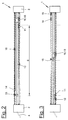
- Figures 2 and 3 show the two end positions of the Carriage movements, the laying carriage (11) in FIG. 2 on the right edge of the discharge belt (5) or Laying width (6) and in figure (3) on the left edge.
- those on the superstructure (10) converging conveyor belts (7,8) from the belt inlet (9) in a substantially horizontal band section directly led to the laying car (11).
- Such a design is e.g. known from EP 0 315 930.
- the two conveyor belts running in parallel become casual (7,8) between uppercarriage (10) and laying carriage (11) over a stationary deflection roller arrangement (37) in the frame (2) guided.
- the fleece layer (1) shown can be a so-called Paper felt storage, which is for particularly large laying widths (6) is suitable. At least there is support for this the lower conveyor belt dreams (26,27) advantageous. A Such support can also be found in nonwoven layers successfully used with a smaller laying width.
- the Support consists of at least one auxiliary car (12, 13), which can be moved back and forth over the discharge belt (5) is stored.
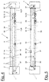
- FIG. 4 shows this Arrangement.
- One support carriage (12) is freely movable stored and is in a drive connection (28) the uppercarriage (10).
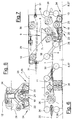
- the drive connection (28) is off Figure 5 can be seen.
- Figure 4 shows the same Carriage position to guide the conveyor belts (7,8).
- the coupled support carriage (13) is on a lower approach (25) of the superstructure (10) arranged. Due to its structural Integration does not have its own castors (34).
- the rigid coupling or the drive connection (28) e.g. from one over fixed castors circulating rope drive can exist, the two support carriages (12, 13) synchronized with the superstructure (10) with the same direction and speed.
- the coupled support car (13) independently movable on the Carriage guide (18) or other suitable location be stored. He is then through with the uppercarriage (10) rigidly connected to a rod or the like.
- Figures 2 and 3 illustrate the positions of the support car (12.13). If the laying carriage (11) is in a narrow position Neighborhood to the uppercarriage (10) on the right edge of the Laying width (6), the free support carriage (12) a position in about half of the laying width which he the long spread conveyor belt strand (26) between Laying carriage (11) and the left frame (2) approximately in the middle supported. Figure 2 shows this arrangement. In the other The laying carriage is in the extreme position according to FIG (11) and the support carriage (12) side by side on the other edge the laying width (6). The superstructure (10) with its The tensioning carriage (13) then takes a position approximately in the middle Insert width (6) and then support it after the right side spread out lower conveyor belt strand (27) between the laying carriage (11) and the right frame (2).
- the belt guide of the conveyor belt dreams (26, 27) on the two Support carriage (12, 13) is preferably of the same design. In a modified embodiment, it can also vary. In the embodiment shown there are the inlet (23) and the outlet (24) for the Conveyor belt dreams (26, 27) each at the same level.
- the support car (12, 13) has one Omega guide (19) for the conveyor belt dreams (26, 27). she e.g. from three pulleys (20,21,22), the parallel to each other and with their axes in a triangle are arranged.
- the conveyor belt dreams (26,27) are under the two outer pulleys (20,22) and inside in a raised loop over the middle pulley (21) performed. With this omega guide (19), too Maintain tape tension in an advantageous manner.
- more than three pulleys can be arranged.
- the tensioning carriage (15) does this from the left frame (2) returning conveyor belt (7), steers it with his Deflection roller (38) uni 180 ° and leads it back into the left frame (2).
- it can be via a tensioning device be tightened additionally and then passes through others Deflections and a lift on the superstructure (10) to the tape inlet (9).
- the lower tensioning carriage (15) is on one, for example upper carriage guide (17) by means of rollers (34) movably supported and has a protruding downward Housing part. His deflection roller (38) is thereby in the area above the laying carriage (11) and support carriage (12) as well as below the top edge and the tape inlet (9) of the superstructure (10).
- the lower tension carriage (15) can thereby according to Figure 3 above the laying carriage (11) and move the support carriage (12) and its tension loop to extend to the uppercarriage (10).
- the lower tensioning carriage (15) is in one Drive connection (31) with the superstructure (10) and moved back and forth synchronously with this. His route corresponds to half the laying width (6).
- Figure 5 illustrates this drive relationship.
- a circulating rope drive In the embodiment shown there is a circulating rope drive.
- it can alternatively an independent drive act from the superstructure (10) or the Machine control is controlled.
- the other upper tension carriage (14) is also over Rollers (34) on the upper carriage guide (17) movably supported. He is next to with a side distance the lower tension carriage (15) arranged and moves in the same direction with this.
- the upper tension carriage (14) is standing in a drive connection (30) to the laying carriage (11) and is moved back and forth synchronously with it.
- the upper support carriage (16) is also by means of rollers (34) movably mounted on the upper carriage guide (17). It has a support roller (35) over which the upper run the conveyor belt (8) is guided and supported.
- the Support carriage (16) moves between the upper tension carriage (14) and the right frame (2) back and forth and stands in a drive connection (29) with the superstructure (10). This drive connection (29) can be the same as in the others Cases.
- the upper support carriage (16) and the Upper wagons (14) can be above the other main and Move the auxiliary carriage (10, 11, 12, 13).
- the driving length of the the upper wagon (14) corresponds to the full laying width (6) and the travel path of the upper support carriage (16) half Laying width (6).
- the lower conveyor belt run (27) is from the laying carriage (11) over the lower tensioning carriage (13) into the right frame (2) guided, deflected upwards and over the support carriage (16) led to the tensioning carriage (14).
- the upper tension carriage (14) pulls his tension loop with a distance over the superstructure (10) and over the other conveyor belt (7).
- In the right Frame (2) is also a clamping device for Tightening the conveyor belt (8) arranged.
- FIGS. 2 and 3 show the positions of the tensioning carriages (14, 15) and the support carriage (16) in the two outer Laying carriage positions. If the laying carriage (11) on right edge of the laying width (6) are the two Spannwagen (14,15) in a relatively close neighborhood on opposite left edge of the laying width (6) positioned.
- the support carriage (16) is located approximately in the middle between the upper tensioning carriage (14) and the right frame (2). According to the other edge position Figure 3 is the lower tensioning carriage (15) approximately in the middle the laying width (6) positioned while the upper Spannwagen (14) and the support carriage (16) in a relatively narrow Neighborhood to each other and close to the right frame (2) are located.
- the carriage guidance (17, 18) can e.g. Guide rails or - be pipes that run across the discharge belt (5) extend between the side frame parts (2). she are in pairs and to the side of the conveyor belts (7,8) arranged.
- the upper and lower carriage guides (17, 18) are parallel and spaced one above the other. Variations of the embodiment shown are in FIG possible in different ways. For one thing, everyone can Tensioners (14, 15) have an assigned support carriage. In addition, the support car (12,13,16) in number, Arrangement and mode of drive vary. Instead of one The auxiliary car (12, 13, 14, 15, 16) can also be powered by a cable have a belt or chain drive.
- Only one Tension wagons get along.
- the two Main carriage (10.11) through programmable drives that e.g. are equipped with synchronous motors.
- Through an appropriate program or Computer control can move the car Manufacture of different fleece thicknesses or warping over the laying width (6) varies become.
Landscapes
- Engineering & Computer Science (AREA)
- Textile Engineering (AREA)
- Preliminary Treatment Of Fibers (AREA)
- Treatment Of Fiber Materials (AREA)
- Nonwoven Fabrics (AREA)
- Folding Of Thin Sheet-Like Materials, Special Discharging Devices, And Others (AREA)
Applications Claiming Priority (2)
| Application Number | Priority Date | Filing Date | Title |
|---|---|---|---|
| DE29822461U DE29822461U1 (de) | 1998-12-18 | 1998-12-18 | Vliesleger |
| DE29822461U | 1998-12-18 |
Publications (3)
| Publication Number | Publication Date |
|---|---|
| EP1010785A2 true EP1010785A2 (fr) | 2000-06-21 |
| EP1010785A3 EP1010785A3 (fr) | 2001-03-07 |
| EP1010785B1 EP1010785B1 (fr) | 2003-11-05 |
Family
ID=8066757
Family Applications (1)
| Application Number | Title | Priority Date | Filing Date |
|---|---|---|---|
| EP99124702A Expired - Lifetime EP1010785B1 (fr) | 1998-12-18 | 1999-12-11 | Etaleur-nappeur |
Country Status (3)
| Country | Link |
|---|---|
| EP (1) | EP1010785B1 (fr) |
| DE (2) | DE29822461U1 (fr) |
| ES (1) | ES2210953T3 (fr) |
Cited By (2)
| Publication number | Priority date | Publication date | Assignee | Title |
|---|---|---|---|---|
| DE202012102597U1 (de) | 2012-07-13 | 2013-10-14 | Hi Tech Textile Holding Gmbh | Vliesleger |
| DE202013105029U1 (de) | 2013-11-08 | 2015-02-10 | Autefa Solutions Germany Gmbh | Vliesleger |
Family Cites Families (9)
| Publication number | Priority date | Publication date | Assignee | Title |
|---|---|---|---|---|
| DE2654860C2 (de) * | 1976-12-03 | 1985-12-05 | Hergeth Kg Maschinenfabrik Und Apparatebau, 4408 Duelmen | Vliesbandleger zum Legen von Faservliesen auf ein bewegtes Abführungsband |
| US4830351A (en) * | 1988-01-27 | 1989-05-16 | Morrison Berkshire, Inc. | Batt stabilization in cross-lapped web manufacturing apparatus |
| US5289617A (en) * | 1991-06-03 | 1994-03-01 | Asselin (Societe Anonyme) | Spreading and lap-forming machine |
| FR2677046B1 (fr) * | 1991-06-03 | 1995-01-13 | Asselin Ets | Etaleur-nappeur. |
| JPH06116853A (ja) * | 1992-10-05 | 1994-04-26 | Kurashiki Seni Kako Kk | クロスウェブの製造方法 |
| FR2739873A1 (fr) * | 1995-10-13 | 1997-04-18 | Autefa Holding Gmbh | Plieuse de voile et dispositif de fabrication d'un non-tisse |
| DE19543623A1 (de) * | 1995-11-23 | 1997-05-28 | Hergeth Hollingsworth Gmbh I K | Florleger, sowie Verfahren zum Herstellen eines Vlieses |
| DE29518587U1 (de) * | 1995-11-23 | 1997-04-10 | Autefa Maschinenfabrik GmbH, 86316 Friedberg | Vliesleger |
| ES2147049B1 (es) * | 1996-01-25 | 2001-03-16 | Antonio Guasch Grano S L | Maquina napadora de velos de carda. |
-
1998
- 1998-12-18 DE DE29822461U patent/DE29822461U1/de not_active Expired - Lifetime
-
1999
- 1999-12-11 DE DE59907617T patent/DE59907617D1/de not_active Expired - Lifetime
- 1999-12-11 ES ES99124702T patent/ES2210953T3/es not_active Expired - Lifetime
- 1999-12-11 EP EP99124702A patent/EP1010785B1/fr not_active Expired - Lifetime
Cited By (6)
| Publication number | Priority date | Publication date | Assignee | Title |
|---|---|---|---|---|
| DE202012102597U1 (de) | 2012-07-13 | 2013-10-14 | Hi Tech Textile Holding Gmbh | Vliesleger |
| WO2014009520A1 (fr) | 2012-07-13 | 2014-01-16 | Hi Tech Textile Holding Gmbh | Distributeur de voile |
| US9909236B2 (en) | 2012-07-13 | 2018-03-06 | Hi Tech Textile Holding Gmbh | Cross-lapper |
| DE202013105029U1 (de) | 2013-11-08 | 2015-02-10 | Autefa Solutions Germany Gmbh | Vliesleger |
| WO2015067704A1 (fr) | 2013-11-08 | 2015-05-14 | Autefa Solutions Germany Gmbh | Distributeur de voile et procédé de fonctionnement |
| US10309040B2 (en) | 2013-11-08 | 2019-06-04 | Autefa Solutions Germany Gmbh | Nonwoven-laying device and operating method |
Also Published As
| Publication number | Publication date |
|---|---|
| ES2210953T3 (es) | 2004-07-01 |
| EP1010785A3 (fr) | 2001-03-07 |
| EP1010785B1 (fr) | 2003-11-05 |
| DE29822461U1 (de) | 2000-05-18 |
| DE59907617D1 (de) | 2003-12-11 |
Similar Documents
| Publication | Publication Date | Title |
|---|---|---|
| EP0521973B1 (fr) | Procede et dispositif de pose de bandes de non-tisses ou similaires | |
| EP1959038B1 (fr) | Dispositif destiné à la pose d'un voile | |
| EP1975286A1 (fr) | Etaleur-nappeur | |
| EP2479330B1 (fr) | Etaleur-nappeur | |
| EP2479321A1 (fr) | Etaleur-nappeur | |
| EP2157216B1 (fr) | Dispositif destiné à la pose d'un voile | |
| EP1236818A1 (fr) | Procédé et dispositif pour produire des non-tissés isotropes | |
| DE69205335T2 (de) | Vliesbandleger. | |
| EP1975287A1 (fr) | Etaleur-nappeur | |
| DE69205336T2 (de) | Vliesleger. | |
| EP3015578B1 (fr) | Étaleur-nappeur | |
| DE69205351T3 (de) | Vliesbandleger. | |
| EP3150753B1 (fr) | Dispositif pour faire avancer un voile ou une nappe de non-tissé | |
| EP1593761A1 (fr) | Distributeur de voile à bras incliné | |
| EP1816243A1 (fr) | Dispositif de pose d'un non-tissé | |
| EP1010787B1 (fr) | Etaleur-nappeur | |
| EP1010786B1 (fr) | Etaleur-nappeur | |
| EP1828453B1 (fr) | Distributeur de voile et procede de guidage d'un poil | |
| EP1612306B1 (fr) | Etaleur-nappeur | |
| EP1010785B1 (fr) | Etaleur-nappeur | |
| WO2004013390A1 (fr) | Procede et dispositif de distribution de voile | |
| EP3066239A2 (fr) | Dispositif de pose de non-tissé et procédé de pose de non-tissé | |
| DE10250089A1 (de) | Steilarm-Vliesleger und Vorrichtung zum Erzeugen eines kreuzgelegten Faservlieses | |
| DE202012102597U1 (de) | Vliesleger | |
| EP3812490B1 (fr) | Dispositif de protection, procédé de protection et distributeur de non-tissé |
Legal Events
| Date | Code | Title | Description |
|---|---|---|---|
| PUAI | Public reference made under article 153(3) epc to a published international application that has entered the european phase |
Free format text: ORIGINAL CODE: 0009012 |
|
| AK | Designated contracting states |
Kind code of ref document: A2 Designated state(s): BE DE ES FR GB IT |
|
| AX | Request for extension of the european patent |
Free format text: AL;LT;LV;MK;RO;SI |
|
| PUAL | Search report despatched |
Free format text: ORIGINAL CODE: 0009013 |
|
| AK | Designated contracting states |
Kind code of ref document: A3 Designated state(s): AT BE CH CY DE DK ES FI FR GB GR IE IT LI LU MC NL PT SE |
|
| AX | Request for extension of the european patent |
Free format text: AL;LT;LV;MK;RO;SI |
|
| 17P | Request for examination filed |
Effective date: 20010811 |
|
| AKX | Designation fees paid |
Free format text: BE DE ES FR GB IT |
|
| 17Q | First examination report despatched |
Effective date: 20020816 |
|
| RAP1 | Party data changed (applicant data changed or rights of an application transferred) |
Owner name: AUTEFA AUTOMATION GMBH |
|
| GRAH | Despatch of communication of intention to grant a patent |
Free format text: ORIGINAL CODE: EPIDOS IGRA |
|
| GRAS | Grant fee paid |
Free format text: ORIGINAL CODE: EPIDOSNIGR3 |
|
| GRAA | (expected) grant |
Free format text: ORIGINAL CODE: 0009210 |
|
| AK | Designated contracting states |
Kind code of ref document: B1 Designated state(s): BE DE ES FR GB IT |
|
| REG | Reference to a national code |
Ref country code: GB Ref legal event code: FG4D Free format text: NOT ENGLISH |
|
| REF | Corresponds to: |
Ref document number: 59907617 Country of ref document: DE Date of ref document: 20031211 Kind code of ref document: P |
|
| GBT | Gb: translation of ep patent filed (gb section 77(6)(a)/1977) |
Effective date: 20040223 |
|
| REG | Reference to a national code |
Ref country code: ES Ref legal event code: FG2A Ref document number: 2210953 Country of ref document: ES Kind code of ref document: T3 |
|
| ET | Fr: translation filed | ||
| PLBE | No opposition filed within time limit |
Free format text: ORIGINAL CODE: 0009261 |
|
| STAA | Information on the status of an ep patent application or granted ep patent |
Free format text: STATUS: NO OPPOSITION FILED WITHIN TIME LIMIT |
|
| 26N | No opposition filed |
Effective date: 20040806 |
|
| PGFP | Annual fee paid to national office [announced via postgrant information from national office to epo] |
Ref country code: ES Payment date: 20091218 Year of fee payment: 11 |
|
| PGFP | Annual fee paid to national office [announced via postgrant information from national office to epo] |
Ref country code: BE Payment date: 20091221 Year of fee payment: 11 |
|
| BERE | Be: lapsed |
Owner name: *AUTEFA AUTOMATION G.M.B.H. Effective date: 20101231 |
|
| PG25 | Lapsed in a contracting state [announced via postgrant information from national office to epo] |
Ref country code: BE Free format text: LAPSE BECAUSE OF NON-PAYMENT OF DUE FEES Effective date: 20101231 |
|
| REG | Reference to a national code |
Ref country code: ES Ref legal event code: FD2A Effective date: 20120220 |
|
| PG25 | Lapsed in a contracting state [announced via postgrant information from national office to epo] |
Ref country code: ES Free format text: LAPSE BECAUSE OF NON-PAYMENT OF DUE FEES Effective date: 20101212 |
|
| REG | Reference to a national code |
Ref country code: DE Ref legal event code: R082 Ref document number: 59907617 Country of ref document: DE Representative=s name: ERNICKE & ERNICKE, DE |
|
| REG | Reference to a national code |
Ref country code: DE Ref legal event code: R082 Ref document number: 59907617 Country of ref document: DE Representative=s name: ERNICKE PATENT- UND RECHTSANWAELTE, DE Effective date: 20120704 Ref country code: DE Ref legal event code: R082 Ref document number: 59907617 Country of ref document: DE Representative=s name: ERNICKE & ERNICKE, DE Effective date: 20120704 Ref country code: DE Ref legal event code: R081 Ref document number: 59907617 Country of ref document: DE Owner name: AUTEFA SOLUTIONS GERMANY GMBH, DE Free format text: FORMER OWNER: AUTEFA AUTOMATION GMBH, 86316 FRIEDBERG, DE Effective date: 20120704 |
|
| PGFP | Annual fee paid to national office [announced via postgrant information from national office to epo] |
Ref country code: GB Payment date: 20141216 Year of fee payment: 16 |
|
| REG | Reference to a national code |
Ref country code: FR Ref legal event code: PLFP Year of fee payment: 17 |
|
| GBPC | Gb: european patent ceased through non-payment of renewal fee |
Effective date: 20151211 |
|
| PG25 | Lapsed in a contracting state [announced via postgrant information from national office to epo] |
Ref country code: GB Free format text: LAPSE BECAUSE OF NON-PAYMENT OF DUE FEES Effective date: 20151211 |
|
| REG | Reference to a national code |
Ref country code: FR Ref legal event code: PLFP Year of fee payment: 18 |
|
| PGFP | Annual fee paid to national office [announced via postgrant information from national office to epo] |
Ref country code: DE Payment date: 20161216 Year of fee payment: 18 |
|
| PGFP | Annual fee paid to national office [announced via postgrant information from national office to epo] |
Ref country code: IT Payment date: 20161220 Year of fee payment: 18 Ref country code: FR Payment date: 20161221 Year of fee payment: 18 |
|
| REG | Reference to a national code |
Ref country code: DE Ref legal event code: R119 Ref document number: 59907617 Country of ref document: DE |
|
| REG | Reference to a national code |
Ref country code: FR Ref legal event code: ST Effective date: 20180831 |
|
| PG25 | Lapsed in a contracting state [announced via postgrant information from national office to epo] |
Ref country code: DE Free format text: LAPSE BECAUSE OF NON-PAYMENT OF DUE FEES Effective date: 20180703 Ref country code: IT Free format text: LAPSE BECAUSE OF NON-PAYMENT OF DUE FEES Effective date: 20171211 Ref country code: FR Free format text: LAPSE BECAUSE OF NON-PAYMENT OF DUE FEES Effective date: 20180102 |