EP1010837A1 - Plancher d'échafaudage métallique - Google Patents
Plancher d'échafaudage métallique Download PDFInfo
- Publication number
- EP1010837A1 EP1010837A1 EP99124794A EP99124794A EP1010837A1 EP 1010837 A1 EP1010837 A1 EP 1010837A1 EP 99124794 A EP99124794 A EP 99124794A EP 99124794 A EP99124794 A EP 99124794A EP 1010837 A1 EP1010837 A1 EP 1010837A1
- Authority
- EP
- European Patent Office
- Prior art keywords
- tread according
- metal tread
- structures
- wall parts
- metal
- Prior art date
- Legal status (The legal status is an assumption and is not a legal conclusion. Google has not performed a legal analysis and makes no representation as to the accuracy of the status listed.)
- Granted
Links
Images





Classifications
-
- B—PERFORMING OPERATIONS; TRANSPORTING
- B23—MACHINE TOOLS; METAL-WORKING NOT OTHERWISE PROVIDED FOR
- B23K—SOLDERING OR UNSOLDERING; WELDING; CLADDING OR PLATING BY SOLDERING OR WELDING; CUTTING BY APPLYING HEAT LOCALLY, e.g. FLAME CUTTING; WORKING BY LASER BEAM
- B23K9/00—Arc welding or cutting
- B23K9/0026—Arc welding or cutting specially adapted for particular articles or work
-
- B—PERFORMING OPERATIONS; TRANSPORTING
- B21—MECHANICAL METAL-WORKING WITHOUT ESSENTIALLY REMOVING MATERIAL; PUNCHING METAL
- B21D—WORKING OR PROCESSING OF SHEET METAL OR METAL TUBES, RODS OR PROFILES WITHOUT ESSENTIALLY REMOVING MATERIAL; PUNCHING METAL
- B21D39/00—Application of procedures in order to connect objects or parts, e.g. coating with sheet metal otherwise than by plating; Tube expanders
- B21D39/03—Application of procedures in order to connect objects or parts, e.g. coating with sheet metal otherwise than by plating; Tube expanders of sheet metal otherwise than by folding
-
- B—PERFORMING OPERATIONS; TRANSPORTING
- B21—MECHANICAL METAL-WORKING WITHOUT ESSENTIALLY REMOVING MATERIAL; PUNCHING METAL
- B21D—WORKING OR PROCESSING OF SHEET METAL OR METAL TUBES, RODS OR PROFILES WITHOUT ESSENTIALLY REMOVING MATERIAL; PUNCHING METAL
- B21D39/00—Application of procedures in order to connect objects or parts, e.g. coating with sheet metal otherwise than by plating; Tube expanders
- B21D39/03—Application of procedures in order to connect objects or parts, e.g. coating with sheet metal otherwise than by plating; Tube expanders of sheet metal otherwise than by folding
- B21D39/031—Joining superposed plates by locally deforming without slitting or piercing
-
- E—FIXED CONSTRUCTIONS
- E04—BUILDING
- E04G—SCAFFOLDING; FORMS; SHUTTERING; BUILDING IMPLEMENTS OR AIDS, OR THEIR USE; HANDLING BUILDING MATERIALS ON THE SITE; REPAIRING, BREAKING-UP OR OTHER WORK ON EXISTING BUILDINGS
- E04G1/00—Scaffolds primarily resting on the ground
- E04G1/15—Scaffolds primarily resting on the ground essentially comprising special means for supporting or forming platforms; Platforms
- E04G1/152—Platforms made of metal or with metal-supporting frame
Definitions
- the invention relates to a metal plank for Scaffolding, consoles, podiums and the like.
- DE-PS 29 16 826 are planks made of sheet steel or aluminum sheet known, the cross reinforcement profiles are designed as U- or C-shaped cross caps. These have a horizontal thigh and one horizontal lower leg as well as an end face Vertical wall on. The horizontal thigh lies below the tread and the horizontal Lower leg lies on the upper horizontal surface of the several times folded longitudinal reinforcement profile of the two side rails. On the front Vertical webs of the end profile are hooking claws by means of welding with the formation of weld seams attached. The longitudinal stiffening profiles of the longitudinal bars end in front of the vertical web of the cross caps at a distance about the depth of the side flaps corresponds. The cross caps are on the rest Scaffolding floor profile parts also with the formation of Welded seams.
- the cross caps are fixed by welding in such a way that the frontal front edge of the tread in the area of front upper edge of the cross caps with a continuous or multiple interrupted weld it is determined that the front vertical edges of the Longitudinal beam profiles at least in the area of the transition of the frontal vertical wall part of the end profile the lower horizontal cross leg using a Weld seam are set that the lower horizontal cross leg the cross caps in the area of their side Front edges with the horizontal bottom edge of the Longitudinal beam profiles are fixed by means of weld seams and that the inward to the longitudinal center of the gangway pointing side flaps on their vertical front edges with the vertical wall parts of the longitudinal beam profiles are also fixed by means of welds.
- the cross-connection caps used there have horizontal thighs, vertical Side legs, horizontal lower legs and one Vertical outer wall.
- the cross connector caps are by means of hollow, tear-off or blind rivets with the rest Scaffold floor profile structure connected. This allows a connection of the cross-connection caps with the rest Scaffolding floor profile parts without welding and thus local Create overheating as well as light weight, good Stability for long lengths and low stack heights optimized according to practical needs designed.
- the small joining agents mentioned must be used Installation by at suitable points of the Cross-connection cap and the floor profile structure attached through holes are inserted and then reshaped using a conventional forming process become.
- connection technology requires additional Expenses for drilling the through holes at suitable places.
- the manufacture of the Running boards are relatively complex. Because the Cross connector caps must be relative to the rest Scaffolding floor profile parts, especially relative to Suitable for the tread and the longitudinal spars designed additional devices precisely positioned so that on the opposite wall parts the intended through holes. Otherwise, pushing through the small parts disabled or not possible at all.
- planks formed from aluminum sheet which are similar in many features like the planks according to DE-PS 29 16 826.
- the here provided U- or C-shaped cross caps have a horizontal thigh and one horizontal lower leg. Side legs are not intended.
- the cross caps are with the rest Scaffolding floor profile parts with the help of blind rivets attached through through holes of neighboring Wall parts are inserted and subsequently shaped.
- the Tread is with the horizontal upper cross legs the cross caps are fastened with six blind rivets.
- Four of the Blind rivets are in the area of the front edge of the Treads arranged in a transverse row and behind the Blind rivets arranged in the lateral edge areas one is offset in the longitudinal direction Blind rivet provided.
- the cross caps are with the two longitudinal spars each using a separate L-shaped Angled sheet metal part connected by blind rivets.
- the Angled sheet metal part rests with its vertical leg the outer surface of the vertical wall part of the Longitudinal bars on and overlaps with his lower leg outer lateral wall sections of the lower Horizontal cross leg of the end cap. Between the Lower leg of the angle sheet metal part and the lower one Horizontal cross leg of the end profile is a on both sides of these legs horizontal wall part of the longitudinal reinforcement profile of the Longitudinal bars formed. Thereby lie in this Connection area three wall parts on top of each other. This are connected by blind rivets, which are by suitable through holes and are subsequently formed.
- the angle sheet metal part points a width that is one in the longitudinal direction of the Scaffold floors offset arrangement of two Allows blind rivets. The width of the angle sheet metal part corresponds approximately to the depth of the lower horizontal Cross leg of the end cap.
- the are as Hooking claws designed hooking aids on the vertical wall parts of the cross-connection profiles welded to form welds.
- scaffold floors with a tread and with lateral longitudinal stiffening profiles Longitudinal beams known cross-section, the are made in one piece from steel or aluminum.
- each U-shaped or C-shaped on the front End caps made of steel inserted. These have one horizontal thigh, a horizontal one Lower leg, two vertical side legs and one vertical wall part on the front.
- the side legs the end caps have an insertion length that corresponds approximately to 3 times the total height of the gangway.
- These scaffold floors have a relatively large size Weight on.
- the side legs of the end caps are with the vertical walls of the longitudinal spars with the help of Fasteners fastened with a cold-setting joining technique while reshaping the adjacent Have wall parts formed connection structures.
- the cold-set-joint connection structures point from the front end edges of the tread or the longitudinal spars a relatively large distance that corresponds to the height of the Longitudinal bars or the vertical wall parts of the cross caps corresponds.
- the Barriers no optimal power absorption and transmission possible. With high load and / or with load over undesirable material damage or Cracks appear. The resilience of this Barriers are therefore limited.
- the top and Lower legs of the cross caps are not with the Tread and the longitudinal spars connected. That too the resilience of these scaffold floors is limited.
- the longitudinal reinforcement profiles are by repeated Bending formed such that in the lower horizontal, also the support of stacked scaffolding floors serving wall part area two wall parts in parallel lie together.
- the inside wall part is enough about to the middle of the one below horizontal wall part of the longitudinal reinforcement profile. This makes attaching fasteners in this area is not possible or is not a cheap one Arrangement of the same possible.
- scaffold floors have recently been made of sheet steel become known with a horizontal tread and with this longitudinal spar formed in one piece by folding exhibit.
- the longitudinal spars are integral with Bending trained, closed cross-section designed box-shaped longitudinal reinforcement profiles. This are with an outer vertical wall part, a lower, Horizontal wall section designed parallel to the tread and one inclined upwards towards the middle of the scaffolding Inclined wall and an adjoining narrow, lying on the lower surface of the tread Horizontal wall section formed.
- This horizontal wall part the longitudinal reinforcement profiles is with the Tread connected by connecting means, the Connection structures with the help of a cold-set-joining technique trained and in the longitudinal direction of the scaffold floor a row are arranged one behind the other.
- To the End faces of the scaffolding floors can have cross-connection profiles be provided which horizontal top and Have lower legs. The thighs and lower legs and the corresponding horizontal surfaces of the treads and the longitudinal reinforcement profile Through holes through the appropriate rivets inserted and subsequently formed have to.
- planks known from practice are also with a horizontal tread and lateral side rails formed by folding educated. These have on their lower longitudinal edge longitudinal reinforcement profiles formed by folding lower horizontal wall parts on top of each other. There are longitudinal reinforcing ribs between the two side rails provided that also by folding the Tread are formed, down vertically extend and each flanged T-shaped lower have horizontal reinforcing ribs. Between the Tread and the longitudinal spar is a cross connection cap with three upper ones, each in the transverse direction spaced horizontal transverse legs and the inserted on both sides of the side legs. The Cross-connection cap also has two horizontal Lower leg. These are due to the lower ones horizontal surfaces of the reinforcing ribs of the T-shaped trained longitudinal reinforcement webs.
- connection means are with connection structures designed, which are formed by embossing.
- the cross caps have none in the area of the side rails lower horizontal cross leg.
- the horizontal wall parts of the longitudinal reinforcement profiles folded down the longitudinal spars extend to the front end of the Scaffolding floors.
- One under tension and force attack or - Transmission aspects optimized attachment is not possible in this area. Because of this, these are Scaffolding floors only for absorbing low loads suitable.
- the invention is based, the planks of the task type mentioned at the beginning from various perspectives cheaper, especially the Connection of the cross stiffening profiles with the rest Scaffolding floor profile parts with fully automatic Manufacturing possibility taking into account the the resulting manufacturing conditions Boundary conditions and since then, on the scaffold grid dimensions coordinated modular system with little Weight of the crash barriers with no loss of security long-term resilience with regard to the static as well as occurring in rough practice to make dynamic stresses cheaper.
- the manufacture of the gangways is also cheaper because of the cross-bracing profiles not relative to the tread and the longitudinal spars have to be positioned exactly in order to be To allow attachment of the connecting means.
- the fact that the longitudinal spars at their front end one in the transverse direction below the tread extending, integrally formed with the longitudinal spars and spatially separated from the longitudinal stiffening profile Have connecting strap with the lower leg the cross stiffening profile with at least one of the Connecting structures having connecting structures is connected, a particularly manufacturing and inexpensive, the voltage and occurring in practice Power transmission ratio adapted design of the for the overall rigidity and the frame formation of the Walking plank of important front and corner connection area, especially with planks with a usual one Achieve a tread width of at least 300 mm.
- the thigh with the Tread and the side legs with the longitudinal spars each with at least one of the connection structures having connecting means firmly connected.
- This allows a particularly cheap and stable Connection of the cross stiffening profile with the others Scaffold floor profile parts to form a rigid Achieve frame formation, which by using a uniform, fully automatic joining process particularly manufacturing and cost-effective running rail construction without loss of security for a long time Time-bearing resilience enables.
- the connecting tab and the Lower leg a matching joint surface that the simultaneous or sequentially spaced Attaching at least two of the connection structures enables.
- This allows in numbers in a confined space and arrangement on the locally prevailing voltage and Power transmission ratios coordinated connection structures even using uniform Attach joining tools.
- This also means the advantage of uniform in size and training Connection structures, which are an exact computational Stress and stress analysis using modern Calculation methods easier or only possible in a meaningful way makes.
- the joining surfaces are advantageously the same opposite wall parts in the respective Connection areas before connecting essentially designed in parallel and flat. This makes it easier Attach the connection structures to lighter Accessibility of the joining tools and enables structural particularly low-cost connection structures.
- the front edge is advantageously the Connecting strap in the area of the front end of the Lower leg of the cross stiffening profile formed and preferably the connection structures are in the essentially in the area of the front ends of the Longitudinal bars provided.
- the Connecting strap is designed trapezoidal, namely with one in the transition area to the neighboring ones Wall parts of the longitudinal spar arranged trapezoid base edge, whose width is about the depth of the Corresponds to the lower leg of the cross stiffening profile as well as with a trapezoidal bevel edge that is formed obliquely towards the front.
- the transitions are expedient the trapezoidal edges and the transition area of the Connecting strap to the adjoining wall parts of the Longitudinally rounded design.
- the connecting strap connects the lower leg of the cross stiffening profile.
- connection structures with at least two in the direction of the longitudinal axis the gangway spaced, the connecting structures having connecting means with the connecting tab are connected.
- the arrangement and location of the connection structures if they are at a distance from each other that the 10 to 15 times the wall thickness of the connecting bracket and / or the wall thickness of the cross stiffening profile in Overlap area corresponds.
- the adjacent connection structures a distance to each other, which is about 0.4 to 0.5 times that Depth of the lower leg of the cross-bracing profile corresponds.
- connection structures symmetrical to the transverse axis of the cross-bracing profile are arranged and / or by the vertical outer surfaces of the longitudinal spars a distance have approximately the distance between the neighboring Connection structures corresponds.
- the side legs and / or the cross legs rectangular designed.
- the connection of the side legs of the Cross stiffening profile with the longitudinal spars advantageously with three triangular to each other arranged connection structures, expediently two of the three connection structures roughly parallel aligned to the longitudinal axis of the gangplank and below the third connection structure are arranged.
- the two lower connection structures a distance from each other have about the depth of the lower leg of the Corresponds to cross stiffening profile and / or that connecting structure of the front end of the side leg of the cross stiffening profile has a distance which is approximately that Distance of the third connection structure From the two corresponds to the lower connection structures.
- the lower two connection structures from the lower Edge of the side leg or lower leg of the Cross stiffening profile have a distance that the Distance of the end connection structure from corresponds approximately to the front end of the side legs.
- connection structures are arranged so that an equilateral triangle is formed.
- connection of the thigh to the tread plate expediently takes place with three parallel to Front edge of the tread and arranged in a row Connection structures, which expediently from the Front edge of the tread have a distance that about 6 to 9 times the wall thickness of the tread in Connection area corresponds.
- the connecting means are advantageously for Connection of the cross stiffening profiles with the Longitudinal spars and / or the tread plate directly with essentially cold material flow induced by compressive forces each of the wall parts formed, Fully automated connection structures educated. This can cause thermal interference or damage, such as embrittlement of the Materials of the wall parts to be connected or a thermal distortion of the wall parts avoided become. Toxic gases or vapors cannot arise so that no complex suction devices required are. Variations in sheet thickness can also be observed just compensate and it can too Sheet metal wall parts with different sheet thicknesses and / or different materials to high strength and permanent connections.
- connection structures can still be made with a achieve greater static and dynamic strength.
- connection structures are expediently not in place over the outside free surface of each other connected wall parts. This makes it easier Handling the walkway and prevents injuries through protruding connection structures or Parts to be joined. This applies in particular to the case that the connection structures also do not have the inside lying free surface of the interconnected Protruding wall parts.
- connection structures are advantageously included Behind gripping structures, which preferably one the edges of the outer wall parts have engaging locking head. This makes possible a statically and dynamically permanent, firm and visual testable connection with high rationalization potential due to the fully automated connection structures. These are useful for this designed like a push button.
- the wall parts are expediently also in Connection area before connecting to a Provide surface coating or coating. This allows a rational production of those to be connected Wall parts, which before connecting without problems can be stored temporarily without, for example Corrosion problems occur.
- Expedient are those with the surface coating or -coated wall parts after the Attachment of the lanyard without rework connected. This enables inexpensive Production without extensive rework.
- the connecting means contain auxiliary joining parts that preferably with half-hollow rivets or with full rivets are formed. This allows connections with high static and dynamic strength values fully automatic, for example using punch riveting, produce.
- the auxiliary joining parts expediently form at least one of the wall parts to be connected has a closing head out.
- a plastic not deformable material can be used and connecting areas with a high create static and dynamic resilience.
- connection structures exclusively formed with the opposite wall parts.
- filler materials such as solders, welding wires or adhesive, as well as the required dosing or Feeders are omitted and there are none Auxiliary joining parts, such as rivets, screws or the like, and consequently also no separation and / or feeding devices required for this.
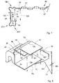
- Fig. 1 shows a small section of a scaffold.
- the stems 30 in one Vertical grid dimension of the scaffolding system corresponding Distance from each other known perforated disks 31 appropriate.
- a horizontal bar 32 with the help of Wedge heads 35 and this and the perforated disc 31st penetrating wedges 34 attached.
- the horizontal bar 32 is a U-profile open to the top with the two lateral vertical legs 37.1 and 37.2 formed. Their upper ends are as support edges 38 for the Hooks 46.1 and 46.2 designed.
- Wedge heads 35 are designed in a known manner with horizontal slots and put on the perforated discs 31 and attached to it with the Wedges 34 secured.
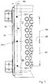
- Fig. 2 shows the here in one piece essentially in the roll-bending process manufactured base profile part 51 made of sheet steel. This is on the lateral side with the profile-like Longitudinal bars 53.1 and 53.2 and the tread plate 65 educated.
- the tread plate 65 has a variety from here circular openings 67, some with perforated edges and partly with downward beaded hole edges are designed. On this way not only a structural reinforcement or Stiffening of the horizontal tread plate 65 and so that the entire plank achieved 45, but one non-slip surface on the one hand and a Possibility of draining fluid substances on the other hand created.
- the openings are 67 evenly over the entire tread plate 65 arranged, in the region of the front ends 63 the bottom section 51 of the horizontal, not with Openings provided tread portion 77 is provided that the openings 67 from the front end 63 a Have distance 78.
- the longitudinal bars 53.1 and 53.2 are with the vertical Wall parts 59 and the up and down subsequent, multiple curved or angled, also forming stacking ribs 58.1, 58.2, 61.1, 61.2, stiffening, upper spar profiles 56.1 and 56.2 as well the lower spar profiles 57.1 and 57.2 designed and have the uniform wall thickness 102.
- the top Spar profiles 56.1 and 56.2 have the same cross-section wave-shaped stacking ribs 58.1 or 58.2 formed. These go horizontally Tread 60 on the one hand and in the vertical wall parts 59 of the longitudinal spars 53 over. On the tread 60 facing away lower end of the longitudinal spars 53 are the lower spar profiles 57.1 or 57.2 as longitudinal stiffening profiles educated.
- the lower spar profiles 57 also end their stacking ribs 61 at a distance 62 in front of the front End 63 of the longitudinal spars 53 or of the base profile part 51.
- the longitudinal spar 53 obliquely upwards in Direction towards the front end 63 of the floor profile part 51 or the longitudinal spar 53 bevelled, namely at an angle 68 of approximately 45 °.
- the vertical wall part 73 which through the parallel trained to the tread 60 and in the longitudinal direction Bottom edge 74 is limited. This has a distance 69 under the bottom 71 of the tread plate 65 or Tread part 77 on.
- the connecting tab 75 is trapezoidal designed. Instead of the ones shown here and below trapezoidal shape described may depend on the respective assembly, joining and strength conditions a different exterior design of the Connection tab 75 may be provided.
- the base line of the trapezoidal base edge 171 Trapezoid is with the lower edge 74 of the vertical Wall part 73 of the longitudinal strut 53 is formed.
- the trapezoid base edge 171 is longer than the other trapezoidal pages and has a length or width 176, which is approximately here the depth 113 of the lower leg 84 of the transverse stiffening profile 50 corresponds.
- Perpendicular to the trapezoid base edge 171 is the parallel to the front edge 126 of the Tread part 77 running front edge 172 trained. This has a length 177 that here approximately 0.5 times the depth 113 of the lower leg 84 corresponds.
- the transition between the front Leading edge 172 and the adjoining, parallel to the trapezoid base edge 171 and behind inside narrow base edge 173 is rounded designed. Their length 178 is slightly larger than here the length 177 of the front edge 172. To the narrow base edge 173 closes at the angle 181 from here about 135 ° obliquely outward Inner edge or trapezoidal bevel edge 174. This points a length of 179.
- the horizontal connecting tab 75 faces from that Tread plate 65 or the tread part 77 a Distance 129 on, the distance 72 of the horizontal-longitudinal leg 70 corresponds to the lower spar profile 57, so that the inner surface 79 of the connecting tab 75 and the inner surface 87 of the horizontal longitudinal leg 70 lie approximately in one plane.
- Fig. 3 shows one of the front in each Base profile part 51 insertable cross stiffening profiles 50, the end profile part or cross-connection cap are trained. This is with the vertical outer wall 81 and the side legs formed by folding 82.1 and 82.2 as well as the thigh 83 and the Lower leg 84 designed and has the following in particular also from FIGS. 4 to 6 Connection conditions that also apply to the hanging hook design are appropriately trained.
- the thigh 83 of the transverse stiffening profile 50 is with the one running parallel to the lower leg 84 Insert part 90 and in the transition area to the vertical outer wall 81 out with the stop and Compensating rib 95 formed.
- the corner transitions between the Vertical outer wall 81 and the vertical stop surface 96 are rounded, while the corner transition to the horizontal Insert part 90 of the horizontal thigh 83 is folded.
- the insertion part 90 has the Depth 98 on.
- the respective lateral outer edge 103 of the thigh 83 is at a distance 104 from the Outer surface 105 of the side leg 82, the larger is the wall thickness 106 of the side leg 82 or the rest, which form the transverse stiffening profile 50 Parts.
- the lower leg 84 of the cross-bracing profile 50 runs predominantly parallel to the insertion part 90 of the Upper leg 83 and is perpendicular to the vertical outer wall 81 trained.
- the distance 111 of the lateral front edge 112 of the lower leg 84 from the outer surface 105 of the respective side leg 82.1 or 82.2 corresponds to the Wall thickness 106 of the cross stiffening profile 50.
- the thigh 83 has a depth 107 and Lower leg 84 has a depth 113, which here are the same size.
- the side leg 82.1 or 82.2 is normal to Vertical outer wall 81 as well as normal to the horizontal Lower leg 84 formed. Its depth 110 is around 1.5 to 1.8 times the depth 107 of the Lower leg 84 or the depth 113 of the thigh 83.
- the distance 116 of its lower edge 117 from the outwardly facing surface 114 of the Lower leg 84 corresponds approximately to the wall thickness 106 of the Cross stiffening profile 50. Its width 118 is smaller than the clear distance 119 between the lower leg 84 and the horizontal insertion part 90 of the thigh 83.
- each laterally arranged circular openings 123 intended in the insertion part 90 of the lower leg 84 are each laterally arranged circular openings 123 intended. These are used to hold hanging devices by means of which the cross-connection cap 50 or entire plank 45 when going through for the Surface treatment of the steel sheets necessary Galvanizing bath can be hung.
- the plank 45 is a hanging aid at both ends the hooks 46.1 and 46.2 are provided. These are for example using an appropriate one Auxiliary device on the vertical outer wall 81 of the Cross stiffening profile 50 welded. The exact The height position of the hooks 46.1 and 46.2 becomes set in such a way that these each with their rear contact surface 121 below the bead 88.1 or 88.2 are applied to the vertical outer wall 81 and as far up until they are with their upper boundary surface 124 on the bead 88.1 or 88.2 issue.
- hooks 46 shown in the figures 46.1, 46.2, which are easy and safe to hang in, especially in that with an open U-profile designed horizontal support bar 32 can in connection with other conditions of support and / or hanging also differently designed mounting aids be provided.
- Designed hooks are also provided on the vertical wall 81 of the transverse stiffening profile 50 are welded on.
- horizontal Swivel tabs can be provided under the round tubes.
- These can be made using suitable connecting means preferably on the lower leg 84 of the Cross stiffening profile 50 be articulated.
- Lanyards can for example through holes in the Lower leg 84 plug-in rivets can be provided.
- mounting aids can also be used be provided, which a hooking of the planks in vertically protruding pins, for example are attached to crossbars or brackets.
- crossbars or brackets For this can the cross stiffening profiles with a sufficient via the front end 63 of the tread plate 65 protruding U-shaped or box-shaped Profile design be formed.
- the thighs and lower legs this profile design can for example be provided with aligned openings, the edges of their holes preferably protrude inwards and are rounded. It
- Other suitable ones can also be used Hole edge configurations can be provided that a secure and easy placement of the running boards on the Enable vertical pins and easy disassembly.
- the cross stiffening profile 50 is in the Floor profile structure of the plank 45 inserted until the stop surface 96 on the end edge 126 of the tread part 77 of the tread plate 65 of the scaffold floor structure strikes (Fig. 8).
- the horizontal insertion part 90 of the thigh 83 des Cross stiffening profile 50 the tread part 77 and the Lower leg 84 lies on the inner surface 79 of the Connection tab 75 on.
- the distance 128 between the outward-facing surface 115 of the horizontal Insert part 90 of the thigh 83 and the outside facing surface 114 of the lower leg 84 is there the same size or slightly smaller than the distance 129 between the inwardly facing bottom 71 of the Tread portion 77 of the tread plate 65 and after inner-facing surface 79 of the connecting strap 75.
- the side legs 82 lie approximately over their entire length 110 on the smooth inner wall 133 of the vertical Wall part 73 of the longitudinal strut 53.
- the distance 97 between the outer surfaces 105.1 and 105.2 of the two Side legs 82.1 and 82.2 are the same size or slightly smaller than the distance 54 between the Inner surfaces 76 of the vertical wall portions 73 of the Longitudinal bars 53.
- this can Cross stiffening profile 50 easily into the floor profile structure the gangplank can be inserted so that a stiff and torsion-resistant frame is formed.
- the thigh and / or the Lower leg and / or the side legs of the cross stiffening profile be arranged so that their Inner surfaces on the outer surfaces of the rest of the Scaffolding floor profile structure of the gangway 45 Lay on or rest on wall parts.
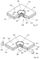
- FIGS. 9 to 11 The exact location and arrangement of the joints or the the connection areas containing connection structures results best from FIGS. 9 to 11.
- Fig. 9 is the connection of the lower leg 84 of the Cross stiffening profile 50 with the connecting strap 75 of the longitudinal spar 53 in the area of one of the end faces Corners of the plank 45 shown.
- the two are there Connection structures 191.1 and 191.2 provided in Longitudinally one behind the other and at a distance 192 are arranged to each other.
- the connection structures 191.1 and 191.2 point from the outer surface 89 of the vertical wall part 73 of the longitudinal bar 53 a distance 193, which corresponds approximately to the distance 192.
- the Connection structures 191.1 and 191.2 are symmetrical to the transverse axis 194 of the lower leg 84 or the Cross stiffening profile 50 arranged.
- Fig. 10 is the location and arrangement of the joints or connecting structures 196.1, 196.2, 196.3 to Connection of the side leg 82 of the cross stiffening profile 50 shown with the longitudinal spar 53. These are arranged triangular to each other.
- the two lower connecting structures 196.1, 196.2 approximately aligned parallel to the longitudinal axis of the gangway 45 and are at a distance 197 from one another. This corresponds approximately to the depth 113 of the lower leg 84 of the Cross stiffening profile 50.
- the connection structure 196.3 is above the two connection structures 196.1 and 196.2 arranged in the horizontal center between them, so that the connection structure 196.3 to the connection structure 196.1 and the connection structure 196.2 has the same horizontal distances 195 or 200.
- the connection structure 196.3 points to the two lower ones Connection structures 196.1 and 196.2 a vertical Distance 198 on. This makes the three Connection structures 196.1, 196.2, 196.3 an equilateral Triangle out.
- the joints or Connection structures 203.1, 203.2, 203.3 are symmetrical to the central longitudinal axis 205 of the plank 45 arranged, and have the same size to each other Distances 206 and 207 on.
- the number, location and arrangement of the above designated joints or connecting structures 191.1, 191.2, 196.1, 196.2, 196.3, 203.1, 203.2, 203.3 is also taking into account the result of the resulting since then Boundary conditions, especially while maintaining an im essentially constant outer shape of the Cross stiffening profile and taking into account the since then, coordinated with the scaffold grid dimensions Modular system and especially in the for the Rigidity and frame design of the entire gangplank important forehead and corner areas occurring static and dynamic loads and the occurring there Tensions and material stresses as well as the Creation of favorable possibilities of a fully automatic Production also with a view to good accessibility to the joining tool of the wall parts to be connected.
- the opposite wall parts are connected preferably with at least partially plastic cold material flow through forming processes, such as Clinching and / or punch riveting.
- the wall parts to be connected are not pre-punched by two sides using suitable joining tools, especially stamps and matrices, as well as possibly Hold-down connected.
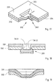
- connection structures 225 and 245 shown are those using Half-rivets 226 or full rivets 246 with the same opposite wall parts 221 and 222 or 241 and 242 formed connection structures 225 and 245 shown.
- the wall parts 221 and 222 first by means of a not shown die and a not shown Hold-down device fixed. In another feed the semi-tubular rivet 226 becomes the connection area fed.
- the half-hollow rivet 226 cuts through the upper wall part 221 and deforms while spreading itself the lower wall part 222 plastically to the closing head 229. Its shape is essentially determined by the shape of the Die tool determined. In the case of Fig.
- the 12 shown embodiment is also the upper Wall part 221 made of a plastically deformable material, so that in this case through plastic cold material flow the wall parts 221, 222 to be connected and the half-hollow rivet 226 formed connection structure 225 is created.
- the stamp-side wall part can, however, also be made from a non-plastically formable one Material.
- connection structure 225 does not have the outer free surface 223 of the other connected wall parts 221, 222 protrudes. in the deformed state reach behind both the spread rivet collar 227 of the semi-tubular rivet 226 as also the plastically deformed partial areas surrounding them 232 of the lower wall part 222 the opening edge 233 of the upper wall part 221. This forms the push button-like designed connection structure 225 a Closing head 229.
- the full rivet 246 has the wall thicknesses 254 and 255 of the wall parts 241 and 242 coordinated distance 256 from the setting head surface 251 of its setting head 248 circumferential annular groove 260.
- a die side Joining tool with a raised ring-shaped Shape is used (not shown in Fig. 13), whereby a plastic flow of Part material areas of the die-side wall part 242 is induced in the annular groove 260 of the full rivet 246.
- the lower wall part 242 has a joining tool after the forming process, the lower annular groove 261 on connects directly to the full rivet 246.
- Half-hollow rivet 226 In a similar way to punch riveting Half-hollow rivet 226 (FIG. 12) is the full rivet 246 with his rivet head forming the setting head 248 so far in the stamp-side upper wall part 241 inserted until the setting head surface 251 in one plane with the outer free surface 243 of the wall part 241. Furthermore, the height 253 of the full rivet 246 is selected so that that the sum of the wall thicknesses 254 and 255 of the Wall parts 241 and 242 correspond to or slightly smaller is. These measures ensure that the Connection structure 245 neither over the outside free surface 243 still over the free surface inside Surface 244 of the interconnected wall parts 241, 242 protrudes.
- connection structures 305, 335, 365 exclusively with the wall parts 301, 302; 331, 332; 361. 362 are formed.
- This, without filler materials or Auxiliary joining parts, made connection is by means of a forming process with or without cutting part under Use of suitably designed joining tools, for example by means of a die and a stamp generated (not shown in Figs. 14 to 21).
- connection structure 305 is one by means of clinching manufactured rectangular connection structure 305 shown.
- the one that develops Connection structure 305 is with the closing head 309 containing rear grip structure 310.
- connection structure 305 comparatively low joining forces required and it cost-effective tool inserts are possible.
- the bar-shaped or rectangular structure of the Connection structure 305 means the formation of a non-rotating joining element.
- the connection structure 305 with the under the edges of the stamp side Wall part 302 push button-like closing head 309 is therefore not above the free one on the outside Surface 303 of the stamp-side wall part 301 protrudes.
- 17 to 19 is another embodiment an enforced connection with a rectangular or bar-shaped Connection structure 335 shown.
- the stamp-side upper wall part 331 is not cut or separated by the stamp. in the Interaction of the die with the stamp forms the closing head shown in cross section in FIG. 18 339 out. There the edges are clearly sheared off 341.1 and 341.2 of the upper stamp-side wall part 331 evident.
- connection structure 335 Compared to that shown in Figs. 14 to 16 Embodiment can be with such Design of the connection structure 335 static and create dynamically more resilient connections that also possible with inexpensive tool sets are.
- This connection structure 335 also has the formed behind the closing head 339 340 on, the closing head 339 the blind of the upper reaches behind the stamp-side wall part 331. Also the Connection structure 335 does not protrude from the outside lying free surface 333 of the upper stamp side Wall part 331 out.
- connection structure 365 is round or circular in shape, unlike those previously described two embodiments neither upper stamp-side wall parts 361 still the lower one wall part 362 on the die side through the not shown stamp is cut or severed. Both wall parts 361 and 362 are with the through plastic cold material flow generated the Connecting structure 370 having a closing head 369 educated.
- the connection structure 365 does not exist either over the outer free surface 363 of the upper, stamp-side wall part 361 emerges.
- connection structures 365 can be used especially materials with a different Formability easily add, so that, for example sandwich sheets can also be advantageously joined.
- connection structures 305, 335, 365 To transfer larger forces also in relative small area wall areas, it is easily possible several of the alternative connection structures 305, 335, 365 to be placed close to each other. This is on the one hand due to a sequential way of working possible or on the other hand that by means of suitable Geometries of the joining tools several connection structures be created at the same time.
- Connection structures 305; 335; 365 are created.
- the connection structures 305; 335; 365 fully automated trainable and connect the opposite wall parts 301, 302; 331, 332; 361, 362 positive and non-positive with each other.
- the lower leg 84 and / or the thigh 83 of the transverse stiffening profile 50 extends approximately over the entire width of the plank 45, 45.1, 45.2 extend.
- the cross stiffening profile 50 is expediently provided with a C- or U-shaped cross-sectional profile. However, this can also depend on the one you want Resilience and the respective dimensions with one cross-sectionally closed box profile his. It can be provided that the box profile the longitudinal bars 53, 53.1, 53.2 or the tread plate 65 is set and / or that this between the Longitudinal bars 53, 53.1, 53.2 is inserted.
- the box profile advantageously extends approximately across the entire width of the gangway.
- the cross stiffening profile 50 expediently has an upwardly extending stop and Compensation rib 95 on. This allows one injury-proof compensation of local unevenness of the tread plate 65 and additional reinforcement create the cross stiffening profile 50. It can be appropriate that the stop and compensation rib 95th has a height 101 that is greater than that Face wall thickness 187 of the tread plate 65.
- cross stiffening profile 50, the tread plate 65 and the longitudinal bars 53, 53.1, 53.2 have a wall thickness 106, 187, 102 which is uniform and the same size. This enables one Inexpensive automatic manufacturing using largely identical joining parameters and a calculable, consistently good quality of the connection.
- the invention relates to a metal plank (45) for scaffolding, consoles, podiums and the like, which has a tread plate (65) and at least two longitudinal struts (53) which are fixed to the carrier and have a cross section. These are formed with a longitudinal stiffening profile arranged under the tread plate (65).
- cross-stiffening profiles (50) are provided which are U-shaped or box-shaped and have thighs, lower legs (84) and / or side legs (82).
- the upper leg is fixed to the tread plate (65), the lower leg (84) and / or the side legs (82) are firmly connected to the longitudinal spars (53) in connection areas formed locally with overlapping wall parts, with at least one of the opposite wall parts in front the connection in the connection area is designed without perforation and / or pre-separation.
- the connecting means are designed so that they can be produced fully automatically with electrical and / or hot or cold material flow induced by pressure forces of at least one of the connecting structures (191.1, 191.2).
- the longitudinal spars (53) are preferably connected underneath the tread plate to the lower leg (84) of the transverse stiffening profile (50) with a transversely extending connecting bracket (75) with at least one of the connecting means (191.1, 191.2).
Landscapes
- Engineering & Computer Science (AREA)
- Mechanical Engineering (AREA)
- Architecture (AREA)
- Plasma & Fusion (AREA)
- Structural Engineering (AREA)
- Physics & Mathematics (AREA)
- Civil Engineering (AREA)
- Joining Of Building Structures In Genera (AREA)
- Laminated Bodies (AREA)
- Ladders (AREA)
- Bridges Or Land Bridges (AREA)
- Bulkheads Adapted To Foundation Construction (AREA)
- Reinforcement Elements For Buildings (AREA)
- Rod-Shaped Construction Members (AREA)
Applications Claiming Priority (2)
| Application Number | Priority Date | Filing Date | Title |
|---|---|---|---|
| DE19858970A DE19858970A1 (de) | 1998-12-19 | 1998-12-19 | Metall-Laufplanke |
| DE19858970 | 1998-12-19 |
Publications (2)
| Publication Number | Publication Date |
|---|---|
| EP1010837A1 true EP1010837A1 (fr) | 2000-06-21 |
| EP1010837B1 EP1010837B1 (fr) | 2007-01-24 |
Family
ID=7891916
Family Applications (1)
| Application Number | Title | Priority Date | Filing Date |
|---|---|---|---|
| EP99124794A Expired - Lifetime EP1010837B1 (fr) | 1998-12-19 | 1999-12-14 | Plancher d'échafaudage métallique |
Country Status (4)
| Country | Link |
|---|---|
| EP (1) | EP1010837B1 (fr) |
| AT (1) | ATE352684T1 (fr) |
| DE (2) | DE19858970A1 (fr) |
| ES (1) | ES2281951T3 (fr) |
Cited By (4)
| Publication number | Priority date | Publication date | Assignee | Title |
|---|---|---|---|---|
| WO2006015602A1 (fr) * | 2004-08-11 | 2006-02-16 | Pf Management Holding Aps | Planche d’echafaudage dotee d’un accessoire a crochets detachable |
| DE102008015066A1 (de) | 2008-03-19 | 2009-09-24 | Wilhelm Layher Verwaltungs-Gmbh | Belageinheit mit Abhebesicherung und Verfahren zur Sicherung einer Belageinheit gegen Abheben sowie Verfahren zur Entsicherung einer gegen Abheben gesicherten Belageinheit |
| EP3354818A1 (fr) * | 2017-01-25 | 2018-08-01 | Andreas Artinger | Dispositif de compensation en longueur pour échafaudages |
| BE1027657B1 (nl) * | 2019-10-11 | 2021-05-11 | Afix Group Nv | Steigervloer en werkwijze voor het produceren van een steigervloer |
Families Citing this family (4)
| Publication number | Priority date | Publication date | Assignee | Title |
|---|---|---|---|---|
| DE202010001213U1 (de) | 2010-01-20 | 2010-04-01 | Gerüstbau Galley GmbH | Gerüst-System-Steckbohle |
| DE102011001497A1 (de) * | 2011-03-23 | 2012-09-27 | Elmenhorst Bauspezialartikel Gmbh & Co. Kg | Verbindungselement für ein bautechnisches Schalungssystem |
| DE202012101000U1 (de) | 2012-03-21 | 2013-03-25 | Wilhelm Layher Verwaltungs-Gmbh | Überlappungs-Anordnung von wenigstens zwei Laufplanken |
| PL3398482T3 (pl) * | 2017-05-05 | 2025-06-09 | Elfa International Ab | Półka |
Citations (4)
| Publication number | Priority date | Publication date | Assignee | Title |
|---|---|---|---|---|
| DE2916826A1 (de) * | 1979-04-26 | 1980-11-06 | Eberhard Layher | Laufplanke aus metall |
| DE19515062A1 (de) | 1995-04-27 | 1996-10-31 | Langer Ruth Geb Layher | Gerüstboden |
| DE29715272U1 (de) * | 1997-08-26 | 1997-11-06 | Baumann Verwertungsgesellschaft Gmbh, 88471 Laupheim | Laufplanke |
| EP0815980A1 (fr) * | 1996-06-25 | 1998-01-07 | Jean-Noel Babu | Pinces pour l'assemblage de produits métalliques plats |
Family Cites Families (1)
| Publication number | Priority date | Publication date | Assignee | Title |
|---|---|---|---|---|
| DE19806092A1 (de) * | 1998-02-14 | 1999-08-19 | Layher W Vermogensverw Gmbh | Gerüstboden |
-
1998
- 1998-12-19 DE DE19858970A patent/DE19858970A1/de not_active Withdrawn
-
1999
- 1999-12-14 AT AT99124794T patent/ATE352684T1/de not_active IP Right Cessation
- 1999-12-14 EP EP99124794A patent/EP1010837B1/fr not_active Expired - Lifetime
- 1999-12-14 ES ES99124794T patent/ES2281951T3/es not_active Expired - Lifetime
- 1999-12-14 DE DE59914167T patent/DE59914167D1/de not_active Expired - Lifetime
Patent Citations (5)
| Publication number | Priority date | Publication date | Assignee | Title |
|---|---|---|---|---|
| DE2916826A1 (de) * | 1979-04-26 | 1980-11-06 | Eberhard Layher | Laufplanke aus metall |
| DE2916826C2 (fr) | 1979-04-26 | 1991-06-13 | Eberhard 7129 Gueglingen De Layher | |
| DE19515062A1 (de) | 1995-04-27 | 1996-10-31 | Langer Ruth Geb Layher | Gerüstboden |
| EP0815980A1 (fr) * | 1996-06-25 | 1998-01-07 | Jean-Noel Babu | Pinces pour l'assemblage de produits métalliques plats |
| DE29715272U1 (de) * | 1997-08-26 | 1997-11-06 | Baumann Verwertungsgesellschaft Gmbh, 88471 Laupheim | Laufplanke |
Cited By (5)
| Publication number | Priority date | Publication date | Assignee | Title |
|---|---|---|---|---|
| WO2006015602A1 (fr) * | 2004-08-11 | 2006-02-16 | Pf Management Holding Aps | Planche d’echafaudage dotee d’un accessoire a crochets detachable |
| DE102008015066A1 (de) | 2008-03-19 | 2009-09-24 | Wilhelm Layher Verwaltungs-Gmbh | Belageinheit mit Abhebesicherung und Verfahren zur Sicherung einer Belageinheit gegen Abheben sowie Verfahren zur Entsicherung einer gegen Abheben gesicherten Belageinheit |
| EP2479360A1 (fr) | 2008-03-19 | 2012-07-25 | Wilhelm Layher Verwaltungs-GmbH | Unité de plaque de sol dotée d'une sécurité contre le soulèvement et procédé de sécurisation d'une unité de plaque de sol ainsi que procédé de déverrouillage d'une unité de plaque de sol protégée contre le soulèvement |
| EP3354818A1 (fr) * | 2017-01-25 | 2018-08-01 | Andreas Artinger | Dispositif de compensation en longueur pour échafaudages |
| BE1027657B1 (nl) * | 2019-10-11 | 2021-05-11 | Afix Group Nv | Steigervloer en werkwijze voor het produceren van een steigervloer |
Also Published As
| Publication number | Publication date |
|---|---|
| ATE352684T1 (de) | 2007-02-15 |
| ES2281951T3 (es) | 2007-10-01 |
| DE19858970A1 (de) | 2000-06-21 |
| DE59914167D1 (de) | 2007-03-15 |
| EP1010837B1 (fr) | 2007-01-24 |
Similar Documents
| Publication | Publication Date | Title |
|---|---|---|
| DE60020075T2 (de) | Verbindungsvorrichtung | |
| DE102016223492B3 (de) | Karosseriestruktur für ein Fahrzeug | |
| DE29917734U1 (de) | Aus einem Profilelement gebildete Montageschiene | |
| WO2008089731A1 (fr) | Planche de bordure pour un échafaudage, et procédé de fabrication d'une planche de bordure | |
| DE19515062A1 (de) | Gerüstboden | |
| EP0735209B1 (fr) | Profilé support transversal ou longitudinal pour revêtement de plafond | |
| EP0736647A1 (fr) | Plate-forme d'echafaudage | |
| EP0936326B1 (fr) | Plate-forme d'échafaudage | |
| EP1010837B1 (fr) | Plancher d'échafaudage métallique | |
| DE3921064A1 (de) | Betonschalungstraeger | |
| EP4131682A1 (fr) | Pièce tête de liaison permettant de fixer une tige de suspension d'un système de porte-câble à un plafond | |
| DE4318838C2 (de) | Wandplatte für Fahrzeugaufbauten | |
| EP1010838A1 (fr) | Plancher d'échafaudage métallique | |
| EP1881123A2 (fr) | Rail profilé pour façade | |
| DE102012108020A1 (de) | Doppel-U-Gerüstriegel | |
| EP0332746B1 (fr) | Console latérale pour dispositif de support ou de suspension pour câbles tuyaux et objets similaires | |
| DE202016100077U1 (de) | Roste, insbesondere für die Verwendung als Fachboden für Plattenregale oder Schwerlastregale | |
| WO2006037549A1 (fr) | Cadre auxiliaire pour cadre de chassis de vehicule utilitaire | |
| DE4221752A1 (de) | Bauplatte | |
| DE202012104117U1 (de) | Stoßfängerquerträgerbaugruppe | |
| EP1950361B1 (fr) | Plinthe pour un échafaudage et son procédé de fabrication | |
| DE10204638B4 (de) | Verfahren zum Herstellen eines Metallblechtürblatts | |
| EP0813279B1 (fr) | Plaque de tête en tôle préformée | |
| DE102013219317B4 (de) | Verfahren zur Herstellung einer Fahrzeugkarosserie und Fahrzeugkarosserie | |
| DE102018132219B4 (de) | Batteriegehäuse mit einer aus Rahmenstrukturteilen zusammengesetzten Rahmenstruktur |
Legal Events
| Date | Code | Title | Description |
|---|---|---|---|
| PUAI | Public reference made under article 153(3) epc to a published international application that has entered the european phase |
Free format text: ORIGINAL CODE: 0009012 |
|
| AK | Designated contracting states |
Kind code of ref document: A1 Designated state(s): AT BE CH CY DE DK ES FI FR GB GR IE IT LI LU MC NL PT SE |
|
| AX | Request for extension of the european patent |
Free format text: AL;LT;LV;MK;RO;SI |
|
| 17P | Request for examination filed |
Effective date: 20001208 |
|
| AKX | Designation fees paid |
Free format text: AT BE CH CY DE DK ES FI FR GB GR IE IT LI LU MC NL PT SE |
|
| 19U | Interruption of proceedings before grant |
Effective date: 20020727 |
|
| 19W | Proceedings resumed before grant after interruption of proceedings |
Effective date: 20021018 |
|
| 17Q | First examination report despatched |
Effective date: 20050608 |
|
| GRAP | Despatch of communication of intention to grant a patent |
Free format text: ORIGINAL CODE: EPIDOSNIGR1 |
|
| RAP1 | Party data changed (applicant data changed or rights of an application transferred) |
Owner name: WILHELM LAYHER VERWALTUNGS-GMBH |
|
| GRAS | Grant fee paid |
Free format text: ORIGINAL CODE: EPIDOSNIGR3 |
|
| GRAA | (expected) grant |
Free format text: ORIGINAL CODE: 0009210 |
|
| AK | Designated contracting states |
Kind code of ref document: B1 Designated state(s): AT BE CH CY DE DK ES FI FR GB GR IE IT LI LU MC NL PT SE |
|
| PG25 | Lapsed in a contracting state [announced via postgrant information from national office to epo] |
Ref country code: IE Free format text: LAPSE BECAUSE OF FAILURE TO SUBMIT A TRANSLATION OF THE DESCRIPTION OR TO PAY THE FEE WITHIN THE PRESCRIBED TIME-LIMIT Effective date: 20070124 Ref country code: FI Free format text: LAPSE BECAUSE OF FAILURE TO SUBMIT A TRANSLATION OF THE DESCRIPTION OR TO PAY THE FEE WITHIN THE PRESCRIBED TIME-LIMIT Effective date: 20070124 Ref country code: DK Free format text: LAPSE BECAUSE OF FAILURE TO SUBMIT A TRANSLATION OF THE DESCRIPTION OR TO PAY THE FEE WITHIN THE PRESCRIBED TIME-LIMIT Effective date: 20070124 |
|
| REG | Reference to a national code |
Ref country code: GB Ref legal event code: FG4D Free format text: NOT ENGLISH |
|
| REG | Reference to a national code |
Ref country code: CH Ref legal event code: EP |
|
| REG | Reference to a national code |
Ref country code: SE Ref legal event code: TRGR |
|
| REG | Reference to a national code |
Ref country code: IE Ref legal event code: FG4D Free format text: LANGUAGE OF EP DOCUMENT: GERMAN |
|
| REF | Corresponds to: |
Ref document number: 59914167 Country of ref document: DE Date of ref document: 20070315 Kind code of ref document: P |
|
| PG25 | Lapsed in a contracting state [announced via postgrant information from national office to epo] |
Ref country code: PT Free format text: LAPSE BECAUSE OF FAILURE TO SUBMIT A TRANSLATION OF THE DESCRIPTION OR TO PAY THE FEE WITHIN THE PRESCRIBED TIME-LIMIT Effective date: 20070625 |
|
| ET | Fr: translation filed | ||
| GBV | Gb: ep patent (uk) treated as always having been void in accordance with gb section 77(7)/1977 [no translation filed] |
Effective date: 20070124 |
|
| REG | Reference to a national code |
Ref country code: IE Ref legal event code: FD4D |
|
| REG | Reference to a national code |
Ref country code: ES Ref legal event code: FG2A Ref document number: 2281951 Country of ref document: ES Kind code of ref document: T3 |
|
| PG25 | Lapsed in a contracting state [announced via postgrant information from national office to epo] |
Ref country code: GB Free format text: LAPSE BECAUSE OF FAILURE TO SUBMIT A TRANSLATION OF THE DESCRIPTION OR TO PAY THE FEE WITHIN THE PRESCRIBED TIME-LIMIT Effective date: 20070124 |
|
| PLBE | No opposition filed within time limit |
Free format text: ORIGINAL CODE: 0009261 |
|
| STAA | Information on the status of an ep patent application or granted ep patent |
Free format text: STATUS: NO OPPOSITION FILED WITHIN TIME LIMIT |
|
| 26N | No opposition filed |
Effective date: 20071025 |
|
| PG25 | Lapsed in a contracting state [announced via postgrant information from national office to epo] |
Ref country code: GR Free format text: LAPSE BECAUSE OF FAILURE TO SUBMIT A TRANSLATION OF THE DESCRIPTION OR TO PAY THE FEE WITHIN THE PRESCRIBED TIME-LIMIT Effective date: 20070425 |
|
| BERE | Be: lapsed |
Owner name: WILHELM LAYHER VERWALTUNGS-GMBH Effective date: 20071231 |
|
| PG25 | Lapsed in a contracting state [announced via postgrant information from national office to epo] |
Ref country code: MC Free format text: LAPSE BECAUSE OF NON-PAYMENT OF DUE FEES Effective date: 20071231 |
|
| REG | Reference to a national code |
Ref country code: CH Ref legal event code: PL |
|
| PG25 | Lapsed in a contracting state [announced via postgrant information from national office to epo] |
Ref country code: BE Free format text: LAPSE BECAUSE OF NON-PAYMENT OF DUE FEES Effective date: 20071231 |
|
| PG25 | Lapsed in a contracting state [announced via postgrant information from national office to epo] |
Ref country code: LI Free format text: LAPSE BECAUSE OF NON-PAYMENT OF DUE FEES Effective date: 20071231 Ref country code: CH Free format text: LAPSE BECAUSE OF NON-PAYMENT OF DUE FEES Effective date: 20071231 |
|
| PG25 | Lapsed in a contracting state [announced via postgrant information from national office to epo] |
Ref country code: AT Free format text: LAPSE BECAUSE OF NON-PAYMENT OF DUE FEES Effective date: 20071214 |
|
| PG25 | Lapsed in a contracting state [announced via postgrant information from national office to epo] |
Ref country code: CY Free format text: LAPSE BECAUSE OF FAILURE TO SUBMIT A TRANSLATION OF THE DESCRIPTION OR TO PAY THE FEE WITHIN THE PRESCRIBED TIME-LIMIT Effective date: 20070124 |
|
| PG25 | Lapsed in a contracting state [announced via postgrant information from national office to epo] |
Ref country code: LU Free format text: LAPSE BECAUSE OF NON-PAYMENT OF DUE FEES Effective date: 20071214 |
|
| REG | Reference to a national code |
Ref country code: FR Ref legal event code: PLFP Year of fee payment: 17 |
|
| REG | Reference to a national code |
Ref country code: FR Ref legal event code: PLFP Year of fee payment: 18 |
|
| REG | Reference to a national code |
Ref country code: FR Ref legal event code: PLFP Year of fee payment: 19 |
|
| PGFP | Annual fee paid to national office [announced via postgrant information from national office to epo] |
Ref country code: NL Payment date: 20181217 Year of fee payment: 20 Ref country code: SE Payment date: 20181219 Year of fee payment: 20 |
|
| PGFP | Annual fee paid to national office [announced via postgrant information from national office to epo] |
Ref country code: IT Payment date: 20181218 Year of fee payment: 20 Ref country code: FR Payment date: 20181218 Year of fee payment: 20 |
|
| PGFP | Annual fee paid to national office [announced via postgrant information from national office to epo] |
Ref country code: DE Payment date: 20181220 Year of fee payment: 20 Ref country code: ES Payment date: 20190121 Year of fee payment: 20 |
|
| REG | Reference to a national code |
Ref country code: DE Ref legal event code: R071 Ref document number: 59914167 Country of ref document: DE |
|
| REG | Reference to a national code |
Ref country code: NL Ref legal event code: MK Effective date: 20191213 |
|
| REG | Reference to a national code |
Ref country code: SE Ref legal event code: EUG |
|
| REG | Reference to a national code |
Ref country code: ES Ref legal event code: FD2A Effective date: 20220127 |
|
| PG25 | Lapsed in a contracting state [announced via postgrant information from national office to epo] |
Ref country code: ES Free format text: LAPSE BECAUSE OF EXPIRATION OF PROTECTION Effective date: 20191215 |