EP1010859A2 - Turbinenschaufel und Methode zum Kühlen einer Turbinenschaufel - Google Patents
Turbinenschaufel und Methode zum Kühlen einer Turbinenschaufel Download PDFInfo
- Publication number
- EP1010859A2 EP1010859A2 EP99310108A EP99310108A EP1010859A2 EP 1010859 A2 EP1010859 A2 EP 1010859A2 EP 99310108 A EP99310108 A EP 99310108A EP 99310108 A EP99310108 A EP 99310108A EP 1010859 A2 EP1010859 A2 EP 1010859A2
- Authority
- EP
- European Patent Office
- Prior art keywords
- chamber
- airfoil
- intermediate partition
- ribs
- edge chamber
- Prior art date
- Legal status (The legal status is an assumption and is not a legal conclusion. Google has not performed a legal analysis and makes no representation as to the accuracy of the status listed.)
- Granted
Links
- 238000001816 cooling Methods 0.000 title claims abstract description 67
- 238000000034 method Methods 0.000 title claims description 11
- 238000005192 partition Methods 0.000 claims abstract description 62
- 238000004891 communication Methods 0.000 claims abstract description 3
- 238000005266 casting Methods 0.000 claims description 12
- 238000010926 purge Methods 0.000 abstract description 4
- 239000000919 ceramic Substances 0.000 description 6
- 239000007789 gas Substances 0.000 description 3
- 239000002002 slurry Substances 0.000 description 3
- 238000004519 manufacturing process Methods 0.000 description 2
- 239000002184 metal Substances 0.000 description 2
- 230000001141 propulsive effect Effects 0.000 description 2
- OKTJSMMVPCPJKN-UHFFFAOYSA-N Carbon Chemical compound [C] OKTJSMMVPCPJKN-UHFFFAOYSA-N 0.000 description 1
- 239000000567 combustion gas Substances 0.000 description 1
- 238000010276 construction Methods 0.000 description 1
- 230000003247 decreasing effect Effects 0.000 description 1
- 239000000446 fuel Substances 0.000 description 1
- 229910002804 graphite Inorganic materials 0.000 description 1
- 239000010439 graphite Substances 0.000 description 1
- 239000007788 liquid Substances 0.000 description 1
- 238000003754 machining Methods 0.000 description 1
- 239000000463 material Substances 0.000 description 1
- 239000000203 mixture Substances 0.000 description 1
- 239000007787 solid Substances 0.000 description 1
- 230000008646 thermal stress Effects 0.000 description 1
- 238000011144 upstream manufacturing Methods 0.000 description 1
Images


Classifications
-
- F—MECHANICAL ENGINEERING; LIGHTING; HEATING; WEAPONS; BLASTING
- F01—MACHINES OR ENGINES IN GENERAL; ENGINE PLANTS IN GENERAL; STEAM ENGINES
- F01D—NON-POSITIVE DISPLACEMENT MACHINES OR ENGINES, e.g. STEAM TURBINES
- F01D5/00—Blades; Blade-carrying members; Heating, heat-insulating, cooling or antivibration means on the blades or the members
- F01D5/12—Blades
- F01D5/14—Form or construction
- F01D5/18—Hollow blades, i.e. blades with cooling or heating channels or cavities; Heating, heat-insulating or cooling means on blades
- F01D5/187—Convection cooling
-
- F—MECHANICAL ENGINEERING; LIGHTING; HEATING; WEAPONS; BLASTING
- F05—INDEXING SCHEMES RELATING TO ENGINES OR PUMPS IN VARIOUS SUBCLASSES OF CLASSES F01-F04
- F05D—INDEXING SCHEME FOR ASPECTS RELATING TO NON-POSITIVE-DISPLACEMENT MACHINES OR ENGINES, GAS-TURBINES OR JET-PROPULSION PLANTS
- F05D2260/00—Function
- F05D2260/20—Heat transfer, e.g. cooling
- F05D2260/221—Improvement of heat transfer
- F05D2260/2214—Improvement of heat transfer by increasing the heat transfer surface
- F05D2260/22141—Improvement of heat transfer by increasing the heat transfer surface using fins or ribs
-
- Y—GENERAL TAGGING OF NEW TECHNOLOGICAL DEVELOPMENTS; GENERAL TAGGING OF CROSS-SECTIONAL TECHNOLOGIES SPANNING OVER SEVERAL SECTIONS OF THE IPC; TECHNICAL SUBJECTS COVERED BY FORMER USPC CROSS-REFERENCE ART COLLECTIONS [XRACs] AND DIGESTS
- Y02—TECHNOLOGIES OR APPLICATIONS FOR MITIGATION OR ADAPTATION AGAINST CLIMATE CHANGE
- Y02T—CLIMATE CHANGE MITIGATION TECHNOLOGIES RELATED TO TRANSPORTATION
- Y02T50/00—Aeronautics or air transport
- Y02T50/60—Efficient propulsion technologies, e.g. for aircraft
Definitions
- a turbine engine typically includes a core engine having, in serial flow relationship, a high pressure compressor which compresses an airflow entering the core engine, a combustor in which a mixture of fuel and compressed air is burned to generate a propulsive gas flow, and a high pressure turbine which is rotated by the propulsive gas flow.
- the high pressure turbine may be connected to the high pressure compressor by a shaft so that the high pressure turbine drives the high pressure compressor.
- Additional compressors and turbines e.g., a low pressure compressor and a low pressure turbine
- turbine includes, without limitation, high pressure turbines and low pressure turbines
- the flow variation through a five-pass airfoil cooling circuit is greater than the flow variation through a three-pass airfoil cooling circuit due to higher airflow velocity, and an associated higher pressure loss, through the five-pass cooling circuit.
- Controlling air flow through a five-pass airfoil cooling circuit therefore is more difficult than controlling air flow through a three-pass cooling circuit.
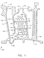
- Airfoil 100 includes a three-pass serpentine shaped cooling cavity 102 which is utilized to cool airfoil 100 with high pressure compressor air. Cavity 102 is formed by an inner wall 104 of airfoil 100. Inner wall 104 includes a leading end 106 and a trailing end 108 that correspond to the leading edge and the trailing edge of airfoil 100. Inner wall 104 also includes a concave portion (not shown in Figure 1) and a convex portion (not shown in Figure 1) that correspond to a concave wall (not shown) and a convex wall (not shown) of airfoil 100. Inner wall 104 further includes a top portion 110 and a bottom portion 112 that correspond to a top (not shown), and a bottom (not shown) of airfoil 100.
- intermediate chamber 116 to leading edge chamber 114 and trailing edge chamber 118, and pins 130 to turbulators 124 vary with the intended use of airfoil 100. However, a relationship between pins 130 and ribs 124 may be established.
- Pins 130 are circular in nature and have a diameter that is proportional to the spacing between pins 130. Alternatively, pins 130 may have an oval shape or they may have another non-circular shape.
- the wax airfoil with the ceramic core is then dipped in a ceramic slurry and allowed to dry. This procedure is repeated several times such that a shell is formed over the wax airfoil.
- the wax is then melted out of the shell leaving a mold with a core suspended inside, and into which molten metal is poured. After the metal has solidified the shell is broken away and the core removed.
- the cooling air then enters the trailing edge chamber 118 past metering partition 142.
- the location and use of metering partition 142 reduces the pressure of the cooling air flowing from intermediate chamber 116 past metering partition 142 and into trailing edge chamber 118.
- the reduced pressure in trailing edge chamber 118 enables producible cast trailing edge slot size.
- Figure 4 is a cross-sectional view of intermediate chamber 116 shown in Figure 3 along line 4-4 and has the same reference numerals as Figures 1, 2, and 3 except that some reference numerals are added to illustrate a concave portion 152 and a convex portion 154 of inner wall 104 in intermediate chamber 116.
Landscapes
- Engineering & Computer Science (AREA)
- Mechanical Engineering (AREA)
- General Engineering & Computer Science (AREA)
- Turbine Rotor Nozzle Sealing (AREA)
Applications Claiming Priority (2)
| Application Number | Priority Date | Filing Date | Title |
|---|---|---|---|
| US215858 | 1988-07-06 | ||
| US09/215,858 US6132169A (en) | 1998-12-18 | 1998-12-18 | Turbine airfoil and methods for airfoil cooling |
Publications (3)
| Publication Number | Publication Date |
|---|---|
| EP1010859A2 true EP1010859A2 (de) | 2000-06-21 |
| EP1010859A3 EP1010859A3 (de) | 2002-11-06 |
| EP1010859B1 EP1010859B1 (de) | 2009-08-05 |
Family
ID=22804697
Family Applications (1)
| Application Number | Title | Priority Date | Filing Date |
|---|---|---|---|
| EP99310108A Expired - Lifetime EP1010859B1 (de) | 1998-12-18 | 1999-12-15 | Kühlsystem für eine Turbinenschaufel mit einem Dreiwegekühlkanal |
Country Status (4)
| Country | Link |
|---|---|
| US (1) | US6132169A (de) |
| EP (1) | EP1010859B1 (de) |
| JP (1) | JP4537518B2 (de) |
| DE (1) | DE69941208D1 (de) |
Cited By (7)
| Publication number | Priority date | Publication date | Assignee | Title |
|---|---|---|---|---|
| EP1519008A1 (de) * | 2003-09-25 | 2005-03-30 | Siemens Westinghouse Power Corporation | Innengekühltes strömungsleitendes Komponent und Kühlverfahren für dieses Komponent |
| EP1645722A3 (de) * | 2004-10-06 | 2009-01-14 | General Electric Company | Turbinenschaufel mit gestuften Kühlluft-Auslassschlitzen |
| US8801366B2 (en) | 2008-03-28 | 2014-08-12 | Alstom Technology Ltd. | Stator blade for a gas turbine and gas turbine having same |
| WO2016030307A1 (de) * | 2014-08-27 | 2016-03-03 | Siemens Aktiengesellschaft | Turbinenschaufel und turbine |
| WO2016134907A3 (de) * | 2015-02-23 | 2016-11-03 | Siemens Aktiengesellschaft | Leit- oder laufschaufeleinrichtung und giesskern |
| EP3196415A1 (de) * | 2016-01-25 | 2017-07-26 | Rolls-Royce Corporation | Gekühlte turbinenleitschaufel |
| DE102024204952A1 (de) * | 2024-05-28 | 2025-12-04 | Siemens Energy Global GmbH & Co. KG | Leitschaufel |
Families Citing this family (35)
| Publication number | Priority date | Publication date | Assignee | Title |
|---|---|---|---|---|
| US6398501B1 (en) | 1999-09-17 | 2002-06-04 | General Electric Company | Apparatus for reducing thermal stress in turbine airfoils |
| US6491496B2 (en) | 2001-02-23 | 2002-12-10 | General Electric Company | Turbine airfoil with metering plates for refresher holes |
| US6471479B2 (en) | 2001-02-23 | 2002-10-29 | General Electric Company | Turbine airfoil with single aft flowing three pass serpentine cooling circuit |
| US6599092B1 (en) * | 2002-01-04 | 2003-07-29 | General Electric Company | Methods and apparatus for cooling gas turbine nozzles |
| US6932570B2 (en) * | 2002-05-23 | 2005-08-23 | General Electric Company | Methods and apparatus for extending gas turbine engine airfoils useful life |
| US6746209B2 (en) | 2002-05-31 | 2004-06-08 | General Electric Company | Methods and apparatus for cooling gas turbine engine nozzle assemblies |
| US6851924B2 (en) * | 2002-09-27 | 2005-02-08 | Siemens Westinghouse Power Corporation | Crack-resistance vane segment member |
| US6969230B2 (en) | 2002-12-17 | 2005-11-29 | General Electric Company | Venturi outlet turbine airfoil |
| US6884036B2 (en) * | 2003-04-15 | 2005-04-26 | General Electric Company | Complementary cooled turbine nozzle |
| US6902372B2 (en) * | 2003-09-04 | 2005-06-07 | Siemens Westinghouse Power Corporation | Cooling system for a turbine blade |
| US7008179B2 (en) * | 2003-12-16 | 2006-03-07 | General Electric Co. | Turbine blade frequency tuned pin bank |
| US7044709B2 (en) * | 2004-01-15 | 2006-05-16 | General Electric Company | Methods and apparatus for coupling ceramic matrix composite turbine components |
| US7156619B2 (en) * | 2004-12-21 | 2007-01-02 | Pratt & Whitney Canada Corp. | Internally cooled gas turbine airfoil and method |
| US7156620B2 (en) * | 2004-12-21 | 2007-01-02 | Pratt & Whitney Canada Corp. | Internally cooled gas turbine airfoil and method |
| US7217097B2 (en) * | 2005-01-07 | 2007-05-15 | Siemens Power Generation, Inc. | Cooling system with internal flow guide within a turbine blade of a turbine engine |
| US7641445B1 (en) | 2006-12-01 | 2010-01-05 | Florida Turbine Technologies, Inc. | Large tapered rotor blade with near wall cooling |
| US8087892B1 (en) * | 2008-02-22 | 2012-01-03 | Florida Turbine Technologies, Inc. | Turbine blade with dual serpentine flow circuits |
| US20090293495A1 (en) * | 2008-05-29 | 2009-12-03 | General Electric Company | Turbine airfoil with metered cooling cavity |
| US8142153B1 (en) * | 2009-06-22 | 2012-03-27 | Florida Turbine Technologies, Inc | Turbine vane with dirt separator |
| US8757961B1 (en) * | 2011-05-21 | 2014-06-24 | Florida Turbine Technologies, Inc. | Industrial turbine stator vane |
| US9145780B2 (en) | 2011-12-15 | 2015-09-29 | United Technologies Corporation | Gas turbine engine airfoil cooling circuit |
| US9260972B2 (en) | 2012-07-03 | 2016-02-16 | United Technologies Corporation | Tip leakage flow directionality control |
| US9957817B2 (en) | 2012-07-03 | 2018-05-01 | United Technologies Corporation | Tip leakage flow directionality control |
| US9951629B2 (en) | 2012-07-03 | 2018-04-24 | United Technologies Corporation | Tip leakage flow directionality control |
| US9777582B2 (en) | 2012-07-03 | 2017-10-03 | United Technologies Corporation | Tip leakage flow directionality control |
| US10612390B2 (en) | 2017-01-26 | 2020-04-07 | United Technologies Corporation | Trailing edge pressure and flow regulator |
| US10718219B2 (en) | 2017-12-13 | 2020-07-21 | Solar Turbines Incorporated | Turbine blade cooling system with tip diffuser |
| US10989067B2 (en) * | 2018-07-13 | 2021-04-27 | Honeywell International Inc. | Turbine vane with dust tolerant cooling system |
| US10883371B1 (en) | 2019-06-21 | 2021-01-05 | Rolls-Royce Plc | Ceramic matrix composite vane with trailing edge radial cooling |
| US11230929B2 (en) | 2019-11-05 | 2022-01-25 | Honeywell International Inc. | Turbine component with dust tolerant cooling system |
| US11473444B2 (en) * | 2019-11-08 | 2022-10-18 | Raytheon Technologies Corporation | Ceramic airfoil with cooling air turn |
| EP3862537A1 (de) * | 2020-02-10 | 2021-08-11 | General Electric Company Polska sp. z o.o. | Gekühlter turbinenleitschaufelring und turbinenleitschaufelsegment |
| US11220914B1 (en) * | 2020-09-23 | 2022-01-11 | General Electric Company | Cast component including passage having surface anti-freckling element in turn portion thereof, and related removable core and method |
| CN115853600A (zh) * | 2022-12-14 | 2023-03-28 | 中国联合重型燃气轮机技术有限公司 | 燃气轮机叶片和燃气轮机 |
| DE102024202241A1 (de) | 2024-03-11 | 2025-09-11 | Siemens Energy Global GmbH & Co. KG | Leitschaufel |
Family Cites Families (22)
| Publication number | Priority date | Publication date | Assignee | Title |
|---|---|---|---|---|
| US3369792A (en) * | 1966-04-07 | 1968-02-20 | Gen Electric | Airfoil vane |
| US4236870A (en) * | 1977-12-27 | 1980-12-02 | United Technologies Corporation | Turbine blade |
| US4775296A (en) * | 1981-12-28 | 1988-10-04 | United Technologies Corporation | Coolable airfoil for a rotary machine |
| US4474532A (en) * | 1981-12-28 | 1984-10-02 | United Technologies Corporation | Coolable airfoil for a rotary machine |
| FR2725474B1 (fr) * | 1984-03-14 | 1996-12-13 | Snecma | Aube de distributeur de turbine refroidie |
| US5232343A (en) * | 1984-05-24 | 1993-08-03 | General Electric Company | Turbine blade |
| JPS61187501A (ja) * | 1985-02-15 | 1986-08-21 | Hitachi Ltd | 流体冷却構造 |
| JPS62271902A (ja) * | 1986-01-20 | 1987-11-26 | Hitachi Ltd | ガスタ−ビン冷却翼 |
| JPH0833099B2 (ja) * | 1989-02-27 | 1996-03-29 | 株式会社次世代航空機基盤技術研究所 | タービン翼構造 |
| JPH02131001U (de) * | 1989-04-04 | 1990-10-30 | ||
| EP0541207A1 (de) * | 1991-11-04 | 1993-05-12 | General Electric Company | Prallgekühltes Schaufelblatt mit einem die Blatthälften verbundendem Einsatz |
| US5695320A (en) * | 1991-12-17 | 1997-12-09 | General Electric Company | Turbine blade having auxiliary turbulators |
| US5387085A (en) * | 1994-01-07 | 1995-02-07 | General Electric Company | Turbine blade composite cooling circuit |
| US5472316A (en) * | 1994-09-19 | 1995-12-05 | General Electric Company | Enhanced cooling apparatus for gas turbine engine airfoils |
| US5669759A (en) * | 1995-02-03 | 1997-09-23 | United Technologies Corporation | Turbine airfoil with enhanced cooling |
| JPH08296403A (ja) * | 1995-04-25 | 1996-11-12 | Toshiba Corp | ガスタービン空冷翼 |
| JP3241241B2 (ja) * | 1995-08-09 | 2001-12-25 | 三菱重工業株式会社 | 中空ガスタービン翼 |
| JP3396360B2 (ja) * | 1996-01-12 | 2003-04-14 | 三菱重工業株式会社 | ガスタービン冷却動翼 |
| US5772397A (en) * | 1996-05-08 | 1998-06-30 | Alliedsignal Inc. | Gas turbine airfoil with aft internal cooling |
| JP3015743B2 (ja) * | 1996-09-06 | 2000-03-06 | 株式会社東芝 | タービン動翼およびこれを備えた水素燃焼タービンプラント |
| US5738493A (en) * | 1997-01-03 | 1998-04-14 | General Electric Company | Turbulator configuration for cooling passages of an airfoil in a gas turbine engine |
| CA2262701C (en) * | 1997-06-06 | 2003-02-18 | Mitsubishi Heavy Industries, Ltd. | Gas turbine blade |
-
1998
- 1998-12-18 US US09/215,858 patent/US6132169A/en not_active Expired - Lifetime
-
1999
- 1999-11-30 JP JP33911799A patent/JP4537518B2/ja not_active Expired - Fee Related
- 1999-12-15 EP EP99310108A patent/EP1010859B1/de not_active Expired - Lifetime
- 1999-12-15 DE DE69941208T patent/DE69941208D1/de not_active Expired - Lifetime
Non-Patent Citations (1)
| Title |
|---|
| None |
Cited By (10)
| Publication number | Priority date | Publication date | Assignee | Title |
|---|---|---|---|---|
| EP1519008A1 (de) * | 2003-09-25 | 2005-03-30 | Siemens Westinghouse Power Corporation | Innengekühltes strömungsleitendes Komponent und Kühlverfahren für dieses Komponent |
| US6939102B2 (en) | 2003-09-25 | 2005-09-06 | Siemens Westinghouse Power Corporation | Flow guide component with enhanced cooling |
| EP1645722A3 (de) * | 2004-10-06 | 2009-01-14 | General Electric Company | Turbinenschaufel mit gestuften Kühlluft-Auslassschlitzen |
| US8801366B2 (en) | 2008-03-28 | 2014-08-12 | Alstom Technology Ltd. | Stator blade for a gas turbine and gas turbine having same |
| EP2255072B1 (de) * | 2008-03-28 | 2015-05-06 | Alstom Technology Ltd | Leitschaufel für eine gasturbine sowie gasturbine mit einer solchen leitschaufel |
| WO2016030307A1 (de) * | 2014-08-27 | 2016-03-03 | Siemens Aktiengesellschaft | Turbinenschaufel und turbine |
| WO2016134907A3 (de) * | 2015-02-23 | 2016-11-03 | Siemens Aktiengesellschaft | Leit- oder laufschaufeleinrichtung und giesskern |
| EP3196415A1 (de) * | 2016-01-25 | 2017-07-26 | Rolls-Royce Corporation | Gekühlte turbinenleitschaufel |
| US10480328B2 (en) | 2016-01-25 | 2019-11-19 | Rolls-Royce Corporation | Forward flowing serpentine vane |
| DE102024204952A1 (de) * | 2024-05-28 | 2025-12-04 | Siemens Energy Global GmbH & Co. KG | Leitschaufel |
Also Published As
| Publication number | Publication date |
|---|---|
| US6132169A (en) | 2000-10-17 |
| EP1010859B1 (de) | 2009-08-05 |
| JP2000199404A (ja) | 2000-07-18 |
| DE69941208D1 (de) | 2009-09-17 |
| JP4537518B2 (ja) | 2010-09-01 |
| EP1010859A3 (de) | 2002-11-06 |
Similar Documents
| Publication | Publication Date | Title |
|---|---|---|
| US6132169A (en) | Turbine airfoil and methods for airfoil cooling | |
| EP1213444B1 (de) | Mantelringsegment für eine Turbine | |
| EP1367224B1 (de) | Methode und Apparatus zur Kühlung von Leitschaufeln von Gasturbinen | |
| EP1221538B1 (de) | Gekühlte Turbinenleitschaufel | |
| EP1942251B1 (de) | Gekühlte Schaufel mit reduzierten Durchfluss durch die Abströmkantenschlitzen und zugehöriges Giessverfahren | |
| EP1070829B1 (de) | Strömungsmaschinenschaufel mit innerer Kühlung | |
| JP4416417B2 (ja) | ガスタービンノズルを冷却するための方法及び装置 | |
| US7819169B2 (en) | Heat transferring cooling features for an airfoil | |
| US6896487B2 (en) | Microcircuit airfoil mainbody | |
| US6340047B1 (en) | Core tied cast airfoil | |
| US20110236178A1 (en) | Branched airfoil core cooling arrangement | |
| CA2462986A1 (en) | Method and apparatus for cooling an airfoil | |
| KR20050018594A (ko) | 터빈 블레이드용 마이크로회로 냉각 | |
| JP2005155606A (ja) | 3回路タービンブレード | |
| EP1326006A2 (de) | Verfahren und Vorrichtung zur Kühlung von Gasturbinenleitschaufeln | |
| US6485262B1 (en) | Methods and apparatus for extending gas turbine engine airfoils useful life | |
| JP4458772B2 (ja) | ガスタービンエンジンのエーロフォイルの有効寿命を延ばすための方法及び装置 | |
| JP2003214108A (ja) | 改善された温度特性を有する後縁を備えた高圧タービンのための動翼 | |
| US7387492B2 (en) | Methods and apparatus for cooling turbine blade trailing edges | |
| JP7523471B2 (ja) | 翼型用の壁面近傍前縁冷却チャネル |
Legal Events
| Date | Code | Title | Description |
|---|---|---|---|
| PUAI | Public reference made under article 153(3) epc to a published international application that has entered the european phase |
Free format text: ORIGINAL CODE: 0009012 |
|
| AK | Designated contracting states |
Kind code of ref document: A2 Designated state(s): AT BE CH CY DE DK ES FI FR GB GR IE IT LI LU MC NL PT SE |
|
| AX | Request for extension of the european patent |
Free format text: AL;LT;LV;MK;RO;SI |
|
| PUAL | Search report despatched |
Free format text: ORIGINAL CODE: 0009013 |
|
| AK | Designated contracting states |
Kind code of ref document: A3 Designated state(s): AT BE CH CY DE DK ES FI FR GB GR IE IT LI LU MC NL PT SE |
|
| AX | Request for extension of the european patent |
Free format text: AL;LT;LV;MK;RO;SI |
|
| 17P | Request for examination filed |
Effective date: 20030506 |
|
| AKX | Designation fees paid |
Designated state(s): DE FR GB IT |
|
| 17Q | First examination report despatched |
Effective date: 20030612 |
|
| GRAP | Despatch of communication of intention to grant a patent |
Free format text: ORIGINAL CODE: EPIDOSNIGR1 |
|
| RTI1 | Title (correction) |
Free format text: COOLING SYSTEM FOR A TURBINE AIRFOIL HAVING A THREE PASS COOLING CIRCUIT |
|
| GRAS | Grant fee paid |
Free format text: ORIGINAL CODE: EPIDOSNIGR3 |
|
| GRAA | (expected) grant |
Free format text: ORIGINAL CODE: 0009210 |
|
| AK | Designated contracting states |
Kind code of ref document: B1 Designated state(s): DE FR GB IT |
|
| REG | Reference to a national code |
Ref country code: GB Ref legal event code: FG4D |
|
| REF | Corresponds to: |
Ref document number: 69941208 Country of ref document: DE Date of ref document: 20090917 Kind code of ref document: P |
|
| PLBE | No opposition filed within time limit |
Free format text: ORIGINAL CODE: 0009261 |
|
| STAA | Information on the status of an ep patent application or granted ep patent |
Free format text: STATUS: NO OPPOSITION FILED WITHIN TIME LIMIT |
|
| 26N | No opposition filed |
Effective date: 20100507 |
|
| REG | Reference to a national code |
Ref country code: FR Ref legal event code: PLFP Year of fee payment: 17 |
|
| PGFP | Annual fee paid to national office [announced via postgrant information from national office to epo] |
Ref country code: GB Payment date: 20151229 Year of fee payment: 17 |
|
| PGFP | Annual fee paid to national office [announced via postgrant information from national office to epo] |
Ref country code: FR Payment date: 20151217 Year of fee payment: 17 |
|
| PGFP | Annual fee paid to national office [announced via postgrant information from national office to epo] |
Ref country code: DE Payment date: 20151229 Year of fee payment: 17 |
|
| PG25 | Lapsed in a contracting state [announced via postgrant information from national office to epo] |
Ref country code: IT Free format text: LAPSE BECAUSE OF NON-PAYMENT OF DUE FEES Effective date: 20151215 |
|
| REG | Reference to a national code |
Ref country code: DE Ref legal event code: R119 Ref document number: 69941208 Country of ref document: DE |
|
| GBPC | Gb: european patent ceased through non-payment of renewal fee |
Effective date: 20161215 |
|
| PG25 | Lapsed in a contracting state [announced via postgrant information from national office to epo] |
Ref country code: IT Free format text: LAPSE BECAUSE OF NON-PAYMENT OF DUE FEES Effective date: 20151215 |
|
| PGFP | Annual fee paid to national office [announced via postgrant information from national office to epo] |
Ref country code: IT Payment date: 20151222 Year of fee payment: 17 |
|
| PGRI | Patent reinstated in contracting state [announced from national office to epo] |
Ref country code: IT Effective date: 20170710 |
|
| REG | Reference to a national code |
Ref country code: FR Ref legal event code: ST Effective date: 20170831 |
|
| PG25 | Lapsed in a contracting state [announced via postgrant information from national office to epo] |
Ref country code: IT Free format text: LAPSE BECAUSE OF NON-PAYMENT OF DUE FEES Effective date: 20161215 Ref country code: FR Free format text: LAPSE BECAUSE OF NON-PAYMENT OF DUE FEES Effective date: 20170102 |
|
| PGRI | Patent reinstated in contracting state [announced from national office to epo] |
Ref country code: IT Effective date: 20170710 |
|
| PG25 | Lapsed in a contracting state [announced via postgrant information from national office to epo] |
Ref country code: DE Free format text: LAPSE BECAUSE OF NON-PAYMENT OF DUE FEES Effective date: 20170701 Ref country code: GB Free format text: LAPSE BECAUSE OF NON-PAYMENT OF DUE FEES Effective date: 20161215 |