EP1010877A2 - Transmission de course - Google Patents
Transmission de course Download PDFInfo
- Publication number
- EP1010877A2 EP1010877A2 EP99125229A EP99125229A EP1010877A2 EP 1010877 A2 EP1010877 A2 EP 1010877A2 EP 99125229 A EP99125229 A EP 99125229A EP 99125229 A EP99125229 A EP 99125229A EP 1010877 A2 EP1010877 A2 EP 1010877A2
- Authority
- EP
- European Patent Office
- Prior art keywords
- stroke
- lever
- drive element
- lifting element
- lifting
- Prior art date
- Legal status (The legal status is an assumption and is not a legal conclusion. Google has not performed a legal analysis and makes no representation as to the accuracy of the status listed.)
- Granted
Links
- 230000005540 biological transmission Effects 0.000 title claims abstract description 30
- 208000006011 Stroke Diseases 0.000 claims abstract description 146
- 238000000034 method Methods 0.000 claims description 13
- 230000000694 effects Effects 0.000 claims description 11
- 239000000446 fuel Substances 0.000 claims description 5
- 230000007935 neutral effect Effects 0.000 claims description 5
- 239000000919 ceramic Substances 0.000 claims description 2
- 108010014172 Factor V Proteins 0.000 description 31
- 230000001419 dependent effect Effects 0.000 description 3
- 238000006073 displacement reaction Methods 0.000 description 3
- 238000005516 engineering process Methods 0.000 description 3
- 238000002347 injection Methods 0.000 description 3
- 239000007924 injection Substances 0.000 description 3
- 238000004519 manufacturing process Methods 0.000 description 3
- 238000010276 construction Methods 0.000 description 2
- 230000002349 favourable effect Effects 0.000 description 2
- 239000012530 fluid Substances 0.000 description 2
- 239000000463 material Substances 0.000 description 2
- 206010015137 Eructation Diseases 0.000 description 1
- 206010067171 Regurgitation Diseases 0.000 description 1
- 208000027687 belching Diseases 0.000 description 1
- 238000005452 bending Methods 0.000 description 1
- 230000007423 decrease Effects 0.000 description 1
- 238000003780 insertion Methods 0.000 description 1
- 230000037431 insertion Effects 0.000 description 1
- 238000000926 separation method Methods 0.000 description 1
Images



Classifications
-
- F—MECHANICAL ENGINEERING; LIGHTING; HEATING; WEAPONS; BLASTING
- F02—COMBUSTION ENGINES; HOT-GAS OR COMBUSTION-PRODUCT ENGINE PLANTS
- F02B—INTERNAL-COMBUSTION PISTON ENGINES; COMBUSTION ENGINES IN GENERAL
- F02B75/00—Other engines
- F02B75/32—Engines characterised by connections between pistons and main shafts and not specific to preceding main groups
-
- F—MECHANICAL ENGINEERING; LIGHTING; HEATING; WEAPONS; BLASTING
- F02—COMBUSTION ENGINES; HOT-GAS OR COMBUSTION-PRODUCT ENGINE PLANTS
- F02M—SUPPLYING COMBUSTION ENGINES IN GENERAL WITH COMBUSTIBLE MIXTURES OR CONSTITUENTS THEREOF
- F02M51/00—Fuel-injection apparatus characterised by being operated electrically
- F02M51/06—Injectors peculiar thereto with means directly operating the valve needle
- F02M51/061—Injectors peculiar thereto with means directly operating the valve needle using electromagnetic operating means
-
- F—MECHANICAL ENGINEERING; LIGHTING; HEATING; WEAPONS; BLASTING
- F02—COMBUSTION ENGINES; HOT-GAS OR COMBUSTION-PRODUCT ENGINE PLANTS
- F02M—SUPPLYING COMBUSTION ENGINES IN GENERAL WITH COMBUSTIBLE MIXTURES OR CONSTITUENTS THEREOF
- F02M2200/00—Details of fuel-injection apparatus, not otherwise provided for
- F02M2200/21—Fuel-injection apparatus with piezoelectric or magnetostrictive elements
-
- Y—GENERAL TAGGING OF NEW TECHNOLOGICAL DEVELOPMENTS; GENERAL TAGGING OF CROSS-SECTIONAL TECHNOLOGIES SPANNING OVER SEVERAL SECTIONS OF THE IPC; TECHNICAL SUBJECTS COVERED BY FORMER USPC CROSS-REFERENCE ART COLLECTIONS [XRACs] AND DIGESTS
- Y10—TECHNICAL SUBJECTS COVERED BY FORMER USPC
- Y10T—TECHNICAL SUBJECTS COVERED BY FORMER US CLASSIFICATION
- Y10T74/00—Machine element or mechanism
- Y10T74/20—Control lever and linkage systems
- Y10T74/20558—Variable output force
-
- Y—GENERAL TAGGING OF NEW TECHNOLOGICAL DEVELOPMENTS; GENERAL TAGGING OF CROSS-SECTIONAL TECHNOLOGIES SPANNING OVER SEVERAL SECTIONS OF THE IPC; TECHNICAL SUBJECTS COVERED BY FORMER USPC CROSS-REFERENCE ART COLLECTIONS [XRACs] AND DIGESTS
- Y10—TECHNICAL SUBJECTS COVERED BY FORMER USPC
- Y10T—TECHNICAL SUBJECTS COVERED BY FORMER US CLASSIFICATION
- Y10T74/00—Machine element or mechanism
- Y10T74/20—Control lever and linkage systems
- Y10T74/20558—Variable output force
- Y10T74/2057—Variable input leverage
Definitions
- the invention relates to an apparatus and a method for Stroke transmission between a drive element and a Lifting element.
- a hub transmission is often used in an area in a separation of a drive system into a drive element and a lifting element is advantageous, for example due to a simplified production, a material technology different versions or a stroke change.
- a stroke reduction corresponding to a stroke factor ⁇ ⁇ 1
- a stroke ratio occurs at a stroke factor ⁇ > 1, for example in the case of small-stroke actuators whose stroke is to be increased via a lifting element for the necessary application safety.
- the ratio of the area exposed to pressure of the drive element to the exposed surface of the Lift element directly determines the stroke factor.
- a problem with stroke transmission is that a combination of different types of stroke transmission is often required, e.g. B. a neutral stroke transmission at the beginning of an operation with the following stroke ratio, z. B. in a stroke transfer from a piezoelectric actuator to a nozzle needle for operating a servo-valve-controlled fuel injector.
- a high amount of force must be used to open a servo valve chamber precisely and initially. Immediately after the belching, the pressure in the valve chamber drops to a low value, so that a considerably lower force is sufficient for further opening.
- injection quantity, start of injection For the reproducibility of the opening behavior within narrow tolerances (injection quantity, start of injection), a wide opening of the valve chamber is required. Due to the small useful stroke of the piezo actuator, a stroke ratio is necessary.
- a sliding drive element one in the same direction displaceable lifting element and at least one Lever used.
- the lever is permanently on the drive element and can be placed on the lifting element and on a bearing.
- the primary stroke xp at which the lever actually rests on the lifting element and the bearing depends on the particular embodiment and on the primary stroke xp. However, if there is a simultaneous support of the lever on the lifting element, the drive element and the bearing, this results in a lever effect, so that the primary stroke xp can be transferred to the lifting element via the lever effect of the lever.
- the stroke transmission is designed such that the stroke factor ⁇ can be changed at least once by changing at least one contact point with a changing primary stroke xp.
- a contact point is understood to mean a pivot point, a lifting point or a force introduction point.
- a change in a contact point is understood to mean a change in a contact condition, that is to say both a production of a contact, e.g. B. by placing the lever, as well as changing the pivot point, lifting point or force application point.
- Such a mechanical stroke transmission has the advantage that compared to a hydraulic or mechanical-hydraulic Stroke transfer to the use of a fluid chamber can be dispensed with. This results in z. B. the advantage that the secondary stroke xs largely independent of the Actuation time is.
- a very flexible geometric configuration is also expediently of the individual components possible, so that the stroke factor ⁇ can be varied over a wide range. So he is dependent from the primary stroke xp, continuously or abruptly changeable.
- the stroke factor ⁇ can e.g. B. growing, constant, falling or can be combined in any combination.
- the lever For easy adjustment of the stroke factor ⁇ , it is advantageous if the lever always rests on a pivot point on the bearing.
- a lever effect of the levers can be transferred to the lifting element.
- the change of a contact point corresponds to the placement of the lever on the lifting element.
- a stroke factor ⁇ between 1 (e.g. initial Opening the servo valve with high force) to 10 (e.g. wide Regurgitation preferred).
- each lever rests on the drive element via an internal force introduction point.
- the stroke factor ⁇ can in turn be changed by changing the force application point.
- the stroke factor ⁇ can change at least in regions within a stroke interval ⁇ xp ⁇ , but it can also remain constant in regions.
- the (inner and outer) force introduction points are arranged at least in some areas continuously, ie spatially merging. It is thus possible to vary the stroke factor ⁇ continuously with a constant change in the primary stroke xp.
- the lever rests on an at least partially curved surface of the drive element, so that a continuous change in the stroke factor ⁇ can be set at least partially by means of the primary stroke xp.
- a primary stroke xp of 10 ⁇ m to 100 ⁇ m is executable. This is typically the case if that Drive element from a piezo actuator or a magneto or electrostrictive element is driven. Doing so Use of a ceramic multilayer piezo actuator in particular prefers.
- Figure 1 is a sectional side view Means for stroke transmission shown in the starting position, in which two different lifting factors during a lifting process ⁇ can be used.
- a lifting element 1 sits loosely on a drive element 3.
- Two one-sided levers 2 are shown, each of which at a force introduction point 7 on the drive element 3 lie on.
- Each lever 2 is also at a pivot point 5 of a bearing 4.
- the levers 2 are also on one Lift point 6 can be placed on the lifting element 1, in this embodiment by attaching it to a drive element 3 facing top surface 9.
- the lifting element 1 and the drive element 3 are designed such that they are geometrically similar in themselves either under any rotation about the axis of rotation I (completely rotationally symmetrical) or after a rotation through an angle of 360 ° / n (n-fold rotationally symmetrical) are transferable.
- n levers (n ⁇ + ) be uniformly distributed at an angular distance of 360 ° / n from one another
- the lifting element 1 is designed to be completely rotationally symmetrical and the drive element 3 has webs as force introduction points 7 at an angular distance of 360 ° / n.
- the drive element 3 can also be designed to be completely rotationally symmetrical, so that the force introduction points 7 lie on a ring of the drive element 3 about the axis of rotation I.
- the distance between lifting point 6 and pivot point 5 is called Load arm of length L1 + L2 and the distance between the force application point 7 and pivot point 5 is used as a force arm of length L1 designated.
- the primary Driving force Fp is via an actuator, e.g. B. one Piezo actuator, applied, the drive element 3 being a part of the actuator.
- the lifting element 1 by its secondary stroke xs shifted in the same direction, being a secondary Driving force Fs is forwardable.
- Figure 2 shows a sectional side view schematically a stroke transmitter according to Figure 1, in the starting position (Figure 2a), at the time of touchdown Lever 2 on the lifting element 1 (Figure 2b), and after insertion the leverage (Figure 2c).
- Figure 2a shows the image of the hub transmitter analogous to Figure 1 in the starting position.
- a drive means for displacing the drive element 3 can use all types of actuators or actuators become.
- a piezo actuator as a drive means.
- FIG. 2c shows the stroke transmitter with a primary stroke xp> xt.
- a stroke ratio ⁇ L2 / L1 , here: ⁇ > 1, is present.
- the lifting element 1 lifts off the drive element 3 and is displaced solely on the basis of the leverage effect.
- a distance between the drive element 3 and the lifting element 1 can be provided in addition to the distance h in the starting position.
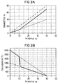
- Figure 3b shows that until the switch point xt is reached the values of the stroke transmitter are those of the direct drive correspond and quickly after reaching the switching point xt drop to the values of the pure lever drive.
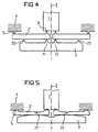
- Figure 4 shows a sectional side view Another embodiment of a stroke transmitter in the starting position.
- the at least two levers 2 lie on one inner force introduction point 71 on the drive element 3 on.
- the lifting element 1 rests on one Lift point 6 on the levers 2 and at a pivot point 5 on the Camp 4 on.
- the lever 2 becomes a mechanical one Non-positive connection between the drive element 3 and the lifting element 1 mediates.
- the drive element 3 is along the axis of rotation I shifted relative to the bearing 4. Because the length L1 of the power arm is equal to the effective length L1 + L2 of lever 2, lever 2 does not Leverage creates, but the primary stroke xp directly Transfer to the lifting element 1 without loss of stroke. At the same time are by the movement of the lifting element 3 relative to the Bear the levers 2 in the direction of the drive element 3 rotated, the inner force application point 71 as Pivotal effect.
- the length L1 of the force arm changes, which is now smaller than the length L1 + L2 of the load arm.
- FIG. 5 shows another embodiment in the starting position shown as a sectional view in side view.
- the surface can also be curved such that a neutral stroke transmission takes place when the drive element 3 is displaced.
- the surface can also be shaped such that the stroke factor ⁇ only changes continuously in sections, for example in that the surface is concave and convex in sections in the direction of the lifting element 1.
- the at least one lever 2 is also a curved, at least on one contact point 5,6,7,71, ..., 7n, 71 ', ..., 7n' has an overlying surface.
- lever bearings e.g. B. cutting edge bearings or roller and bending bearings and combinations thereof.
- An initial direct frictional connection between the drive element (3) and the lifting element (1) can also take place via cams passing laterally past the levers (2).
Landscapes
- Engineering & Computer Science (AREA)
- Chemical & Material Sciences (AREA)
- Combustion & Propulsion (AREA)
- Mechanical Engineering (AREA)
- General Engineering & Computer Science (AREA)
- Physics & Mathematics (AREA)
- Electromagnetism (AREA)
- Transmission Devices (AREA)
- Buildings Adapted To Withstand Abnormal External Influences (AREA)
Applications Claiming Priority (2)
| Application Number | Priority Date | Filing Date | Title |
|---|---|---|---|
| DE19858758A DE19858758C1 (de) | 1998-12-18 | 1998-12-18 | Vorrichtung und Verfahren zur Hubübertragung |
| DE19858758 | 1998-12-18 |
Publications (3)
| Publication Number | Publication Date |
|---|---|
| EP1010877A2 true EP1010877A2 (fr) | 2000-06-21 |
| EP1010877A3 EP1010877A3 (fr) | 2001-06-27 |
| EP1010877B1 EP1010877B1 (fr) | 2004-03-24 |
Family
ID=7891763
Family Applications (1)
| Application Number | Title | Priority Date | Filing Date |
|---|---|---|---|
| EP99125229A Expired - Lifetime EP1010877B1 (fr) | 1998-12-18 | 1999-12-17 | Transmission de course |
Country Status (3)
| Country | Link |
|---|---|
| US (1) | US6367350B1 (fr) |
| EP (1) | EP1010877B1 (fr) |
| DE (2) | DE19858758C1 (fr) |
Families Citing this family (2)
| Publication number | Priority date | Publication date | Assignee | Title |
|---|---|---|---|---|
| GB0217734D0 (en) * | 2002-07-31 | 2002-09-11 | Pbt Ip Ltd | Reversing linkage |
| DE502005010937D1 (de) * | 2005-09-06 | 2011-03-17 | Continental Automotive Gmbh | Kraftstoffeinspritzventil |
Family Cites Families (23)
| Publication number | Priority date | Publication date | Assignee | Title |
|---|---|---|---|---|
| US2649815A (en) * | 1947-12-12 | 1953-08-25 | Kaye & Macdonald Inc | Lever system for steam traps |
| FR988675A (fr) * | 1949-04-13 | 1951-08-30 | Cie Francaise Du Signum | Perfectionnements aux dispositifs de déclenchement mécanique |
| US3045500A (en) * | 1960-08-25 | 1962-07-24 | United Aircraft Corp | Rate device |
| DE2652029C3 (de) * | 1976-11-15 | 1979-10-31 | Bosch-Siemens Hausgeraete Gmbh, 7000 Stuttgart | Kochplatte mit Temperaturfühler und temperaturabhängiger Schalteinrichtung |
| DE2913506A1 (de) * | 1979-04-04 | 1980-10-16 | Amsted Siemag Kette Gmbh | Kraftverstaerker |
| WO1981001806A1 (fr) * | 1979-12-26 | 1981-07-09 | Caterpillar Tractor Co | Procede et dispositif d'assemblage d'une chaine de roulement |
| DE3342951C2 (de) * | 1983-11-26 | 1986-12-18 | Daimler-Benz Ag, 7000 Stuttgart | Betätigungseinrichtung für zwei abhängig voneinander betätigbare Ventile |
| US4609178A (en) * | 1984-02-02 | 1986-09-02 | Baumann Hans D | Diaphragm type control valve |
| FR2580069B1 (fr) * | 1985-04-03 | 1987-05-29 | Seb Sa | |
| US4791824A (en) * | 1987-01-28 | 1988-12-20 | Delphin Corporation | Hydraulic assisted machine |
| DE3800203C2 (de) * | 1988-01-07 | 1997-08-14 | Atlas Fahrzeugtechnik Gmbh | Kraftstoffeinspritzventil |
| DE3920931A1 (de) * | 1989-06-27 | 1991-01-03 | Fev Motorentech Gmbh & Co Kg | Elektromagnetisch arbeitende stelleinrichtung |
| FR2649540B1 (fr) * | 1989-07-06 | 1991-10-18 | Europ Agence Spatiale | Mecanisme de reglage fin de l'orientation et/ou de la position d'une charge utile |
| DE4129832A1 (de) * | 1991-09-07 | 1993-03-25 | Heidelberger Druckmasch Ag | Kraftverstaerkung |
| US5215286A (en) * | 1992-05-26 | 1993-06-01 | Nupro Company | High pressure diaphragm valve |
| US5251502A (en) * | 1992-06-09 | 1993-10-12 | Savair Inc. | Sequential pivot pin multiplier |
| DE4306072C2 (de) * | 1993-02-26 | 1994-12-08 | Siemens Ag | Vorrichtung zum Öffnen und Verschließen einer in einem Gehäuse vorhandenen Durchtrittsöffnung |
| JP3616855B2 (ja) * | 1995-03-13 | 2005-02-02 | 株式会社フジキン | 制御器 |
| DE19519191C2 (de) * | 1995-05-24 | 1997-04-10 | Siemens Ag | Einspritzventil |
| JP3525313B2 (ja) * | 1995-06-30 | 2004-05-10 | 太平洋セメント株式会社 | レバー変位拡大機構付位置決め装置 |
| DE19648730C2 (de) * | 1996-11-25 | 1998-11-19 | Fraunhofer Ges Forschung | Piezoelektrisch betätigtes Mikroventil |
| DE19710601C2 (de) * | 1997-03-14 | 1999-05-20 | Univ Magdeburg Tech | Bewegungsgenerator |
| US5996432A (en) * | 1997-10-31 | 1999-12-07 | Orbea; Cesar Raul Lopez | Torque variator device |
-
1998
- 1998-12-18 DE DE19858758A patent/DE19858758C1/de not_active Expired - Fee Related
-
1999
- 1999-12-17 DE DE59908945T patent/DE59908945D1/de not_active Expired - Lifetime
- 1999-12-17 EP EP99125229A patent/EP1010877B1/fr not_active Expired - Lifetime
- 1999-12-20 US US09/446,405 patent/US6367350B1/en not_active Expired - Lifetime
Also Published As
| Publication number | Publication date |
|---|---|
| US6367350B1 (en) | 2002-04-09 |
| DE59908945D1 (de) | 2004-04-29 |
| DE19858758C1 (de) | 2000-09-07 |
| EP1010877A3 (fr) | 2001-06-27 |
| EP1010877B1 (fr) | 2004-03-24 |
Similar Documents
| Publication | Publication Date | Title |
|---|---|---|
| EP1019628B1 (fr) | Dispositif pour transmettre un deplacement, injecteur comportant un tel dispositif et procede de production d'un tel element de transmission | |
| EP1252432B1 (fr) | Dispositif d'injection de carburant a commande directe pour un moteur a combustion interne a pistons | |
| AT404288B (de) | Motorbremse bei einer brennkraftmaschine für kraftfahrzeuge | |
| DE3707046C2 (fr) | ||
| DE19653555C2 (de) | Piezoelektrischer Aktor | |
| EP0530785A1 (fr) | Distributeur de fluides | |
| DE60115766T2 (de) | Selbstkompensierender piezoelektrischer Aktuator für ein Steuerventil | |
| EP1370763A1 (fr) | Soupape de commande de liquides | |
| DE29717649U1 (de) | Direktgesteuertes Einspritzventil, insbesondere Kraftstoffeinspritzventil | |
| AT519932B1 (de) | Ablassventil für hohe Drücke | |
| DE4442965A1 (de) | Ventiltrieb mit mechanischer Verriegelung | |
| EP1264968A2 (fr) | Appareil pour actionner une soupape à levé variable dans un moteur à combustion interne | |
| EP1010877B1 (fr) | Transmission de course | |
| EP1078157A1 (fr) | Soupape d'injection de carburant | |
| EP2440770A1 (fr) | Soupape d'injection dotée d'une unité de transmission | |
| WO1999017004A1 (fr) | Poussoir pour le mecanisme de distribution d'un moteur a combustion interne | |
| DE4334395C2 (de) | Nocken-Umschaltmechanismus für Motoren | |
| EP0298076B1 (fr) | Soupape injectrice de carburant a commande electrique | |
| CH692487A5 (de) | Hydraulische Spannvorrichtung für die lösbare Präzisionshalterung von Maschinenelementen. | |
| WO2003076770A1 (fr) | Procede de fabrication d'elements de mecanisme de distribution commutables dans un moteur a combustion interne et element de mecanisme de distribution commutable concerne | |
| WO2017207671A1 (fr) | Bielle à longueur variable, dispositif de réglage d'un rapport de compression et moteur à combustion interne | |
| DE19844837B4 (de) | Kraftstoffeinspritzventil für Brennkraftmaschinen | |
| EP4188616A1 (fr) | Valve pour milieux fluides | |
| EP1601869A1 (fr) | Soupape comportant un element ressort, con ue pour un injecteur de carburant | |
| DE19939478C1 (de) | Ventil zum Steuern von Flüssigkeiten |
Legal Events
| Date | Code | Title | Description |
|---|---|---|---|
| PUAI | Public reference made under article 153(3) epc to a published international application that has entered the european phase |
Free format text: ORIGINAL CODE: 0009012 |
|
| AK | Designated contracting states |
Kind code of ref document: A2 Designated state(s): DE FR IT |
|
| AX | Request for extension of the european patent |
Free format text: AL;LT;LV;MK;RO;SI |
|
| PUAL | Search report despatched |
Free format text: ORIGINAL CODE: 0009013 |
|
| AK | Designated contracting states |
Kind code of ref document: A3 Designated state(s): AT BE CH CY DE DK ES FI FR GB GR IE IT LI LU MC NL PT SE |
|
| AX | Request for extension of the european patent |
Free format text: AL;LT;LV;MK;RO;SI |
|
| 17P | Request for examination filed |
Effective date: 20011217 |
|
| AKX | Designation fees paid |
Free format text: DE FR IT |
|
| GRAP | Despatch of communication of intention to grant a patent |
Free format text: ORIGINAL CODE: EPIDOSNIGR1 |
|
| GRAS | Grant fee paid |
Free format text: ORIGINAL CODE: EPIDOSNIGR3 |
|
| GRAA | (expected) grant |
Free format text: ORIGINAL CODE: 0009210 |
|
| AK | Designated contracting states |
Kind code of ref document: B1 Designated state(s): DE FR IT |
|
| REF | Corresponds to: |
Ref document number: 59908945 Country of ref document: DE Date of ref document: 20040429 Kind code of ref document: P |
|
| ET | Fr: translation filed | ||
| PLBE | No opposition filed within time limit |
Free format text: ORIGINAL CODE: 0009261 |
|
| STAA | Information on the status of an ep patent application or granted ep patent |
Free format text: STATUS: NO OPPOSITION FILED WITHIN TIME LIMIT |
|
| 26N | No opposition filed |
Effective date: 20041228 |
|
| REG | Reference to a national code |
Ref country code: FR Ref legal event code: TP |
|
| REG | Reference to a national code |
Ref country code: FR Ref legal event code: PLFP Year of fee payment: 17 |
|
| REG | Reference to a national code |
Ref country code: FR Ref legal event code: PLFP Year of fee payment: 18 |
|
| REG | Reference to a national code |
Ref country code: FR Ref legal event code: PLFP Year of fee payment: 19 |
|
| PGFP | Annual fee paid to national office [announced via postgrant information from national office to epo] |
Ref country code: FR Payment date: 20181219 Year of fee payment: 20 |
|
| PGFP | Annual fee paid to national office [announced via postgrant information from national office to epo] |
Ref country code: DE Payment date: 20181231 Year of fee payment: 20 Ref country code: IT Payment date: 20181220 Year of fee payment: 20 |
|
| REG | Reference to a national code |
Ref country code: DE Ref legal event code: R071 Ref document number: 59908945 Country of ref document: DE |