EP1010917A1 - Amortisseur à haute puissance - Google Patents
Amortisseur à haute puissance Download PDFInfo
- Publication number
- EP1010917A1 EP1010917A1 EP99123288A EP99123288A EP1010917A1 EP 1010917 A1 EP1010917 A1 EP 1010917A1 EP 99123288 A EP99123288 A EP 99123288A EP 99123288 A EP99123288 A EP 99123288A EP 1010917 A1 EP1010917 A1 EP 1010917A1
- Authority
- EP
- European Patent Office
- Prior art keywords
- piston
- gap
- balls
- damping device
- squeeze film
- Prior art date
- Legal status (The legal status is an assumption and is not a legal conclusion. Google has not performed a legal analysis and makes no representation as to the accuracy of the status listed.)
- Granted
Links
- 238000013016 damping Methods 0.000 title claims abstract description 54
- 230000033001 locomotion Effects 0.000 claims abstract description 16
- 238000005096 rolling process Methods 0.000 claims abstract description 11
- 230000013011 mating Effects 0.000 claims description 9
- 239000012530 fluid Substances 0.000 claims description 5
- 230000000717 retained effect Effects 0.000 claims description 4
- 239000007788 liquid Substances 0.000 claims description 3
- 238000007789 sealing Methods 0.000 claims description 2
- 238000000926 separation method Methods 0.000 claims 6
- 230000009471 action Effects 0.000 abstract description 12
- 238000006073 displacement reaction Methods 0.000 description 6
- 229910000831 Steel Inorganic materials 0.000 description 5
- 238000010276 construction Methods 0.000 description 5
- 239000010959 steel Substances 0.000 description 5
- 230000008901 benefit Effects 0.000 description 3
- 230000000694 effects Effects 0.000 description 3
- 230000004048 modification Effects 0.000 description 3
- 238000012986 modification Methods 0.000 description 3
- 238000010521 absorption reaction Methods 0.000 description 2
- 230000006835 compression Effects 0.000 description 2
- 238000007906 compression Methods 0.000 description 2
- 229920001971 elastomer Polymers 0.000 description 2
- 239000000806 elastomer Substances 0.000 description 2
- 239000007787 solid Substances 0.000 description 2
- 210000001364 upper extremity Anatomy 0.000 description 2
- 230000005540 biological transmission Effects 0.000 description 1
- 230000008859 change Effects 0.000 description 1
- 230000001419 dependent effect Effects 0.000 description 1
- 230000003467 diminishing effect Effects 0.000 description 1
- 230000008030 elimination Effects 0.000 description 1
- 238000003379 elimination reaction Methods 0.000 description 1
- 238000005516 engineering process Methods 0.000 description 1
- 238000004519 manufacturing process Methods 0.000 description 1
- 239000000463 material Substances 0.000 description 1
- 230000007246 mechanism Effects 0.000 description 1
- 230000002093 peripheral effect Effects 0.000 description 1
- 230000021715 photosynthesis, light harvesting Effects 0.000 description 1
- 230000004044 response Effects 0.000 description 1
Images


Classifications
-
- F—MECHANICAL ENGINEERING; LIGHTING; HEATING; WEAPONS; BLASTING
- F16—ENGINEERING ELEMENTS AND UNITS; GENERAL MEASURES FOR PRODUCING AND MAINTAINING EFFECTIVE FUNCTIONING OF MACHINES OR INSTALLATIONS; THERMAL INSULATION IN GENERAL
- F16F—SPRINGS; SHOCK-ABSORBERS; MEANS FOR DAMPING VIBRATION
- F16F15/00—Suppression of vibrations in systems; Means or arrangements for avoiding or reducing out-of-balance forces, e.g. due to motion
- F16F15/02—Suppression of vibrations of non-rotating, e.g. reciprocating systems; Suppression of vibrations of rotating systems by use of members not moving with the rotating systems
- F16F15/023—Suppression of vibrations of non-rotating, e.g. reciprocating systems; Suppression of vibrations of rotating systems by use of members not moving with the rotating systems using fluid means
- F16F15/0237—Suppression of vibrations of non-rotating, e.g. reciprocating systems; Suppression of vibrations of rotating systems by use of members not moving with the rotating systems using fluid means involving squeeze-film damping
Definitions
- the present invention relates to vibration damping devices or pads which utilize squeeze film technology to provide energy dissipation.
- the configuration of prior art squeeze film damping pads as applied directly for vibration absorption in supporting machine tools is shown in Canadian Patent No. 1,236,812.
- the damping pad there disclosed employs as two mating damper elements a cylinder cup and piston arrangement in opposed position between the machine tool and a supporting surface for carrying the weight of the machine tool on support pins which serve as very stiff axial compression springs.
- the cylinder and piston damping elements are dimensioned such that when assembled, they define annular spaced walls which define a squeeze film gap with provisions made to fill the gap with a viscous oil.
- the vibrating load which is supported by the support pins applies horizontal vibration displacement by virtue of the support pins being located in oversized holes permitting the pins to deflect slightly and accommodate the squeeze film action in the oil between the walls of the squeeze film gap.
- the squeeze film gap need not be annular to accommodate mating structures which are not necessarily circular.
- the support pins arranged for carrying the load in their axial direction are relatively flexible in a lateral direction and mounted within the confines of clearance holes to permit translation of a small amount of horizontal deflection under the influence of machine vibrations. It is very costly to manufacture the support pins and their respective bored holes accurately enough so that all the pins share the load equally. Specific problems are encountered with different pin lengths and improper hole alignment between the top and bottom members. Misalignment is also a problem when the bolts were used instead of the pins. It is difficult to properly adjust the torque on the bolts so they are all carrying the same load. This is important so the squeeze film annular spacing is uniform throughout the entire circumference of the piston. Furthermore, it is very difficult to maintain squareness between the plane formed by the pin and bolt lengths with the annular squeeze surfaces. This difficulty greatly reduces the effective damping available from the damping device. In some cases actual mechanical binding can occur.
- the present invention provides various forms of squeeze film damping structures with precision spacing between the mating damper elements on which the machine tool, for example, is mounted which maintains the elevation support level of the machine tool while providing a limited degree of freedom between the two damper elements normal to the direction of the load.
- the horizontal deflection due to vibration provides for complimentary compression and expansion of the squeeze film gap defined between the damper elements as vibrations are transmitted to the device.
- the load bearing elements are dimensioned to provide the appropriate gap between the horizontal surfaces of the damper elements and thus provide a high tensile element for load support which is capable of maintaining the designated support level for the machine tool or other load supported by means of the damping device.
- the load bearing elements are free to roll a limited distance within the recesses in which they are contained in a direction substantially perpendicular to the squeeze film gap, thus transmitting lateral deflection to the squeeze film chamber which is uniform throughout the height of the squeeze film chamber.
- the steel balls avoid introduction of any tilting or other misalignment of the load vector supported by the damping device.
- the steel balls are far less expensive that either the pins or the bolts mentioned above and eliminate the load carrying problem as well as any misalignment problems.
- the balls and the ball track are self centering.
- the prior art according to the Canadian patent does not have this centering advantage. It relies on mechanical alignment for the original alignment but transverse loads can make the damping device inoperable by deflecting the position off center.
- the relationship between load and centering is very important in order to maintain the proper damping generated by the squeeze film action.
- the balls and the track maintain this relationship and keep the piston centered.
- the steel balls and their respective race produce a very rigid interface in the load bearing direction.
- the invention allows to support a machine more rigidly to maintain alignment better than the Canadian patent and will, at the same time, yield the same or better damping.
- rollers make the damping device directional. It can constrain a machine structure in such a way as to maximize the damping while eliminating any lateral movement in other directions.
- the self centering concept is maintained as well as all the other advantages mentioned above.
- FIG. 1 shows a squeeze film damping pad constructed in accordance with a first embodiment of the invention which employs an outer cup shaped element 11, having a flat lower support surface 12 for supporting the damping pad and the load that it is carrying.
- Element 11 has a inner cylindrical wall 13 which provides the outer wall of a first squeeze film chamber.
- Extending axially upward from the bottom of cup-shaped element 11 is a piston 14 having an outer cylindrical wall 15 which provides the inner wall of a second squeeze film chamber.
- Element 11 has lower horizontal inner surface 16 recessed at 17 to provide a lower bearing surface 18 which supports elements of an annular ball bearing assembly 19.
- the ball bearing assembly 19 provides a plurality of high tensile spherical balls 21 equidistantly spaced around a circumference by a cage 22 to run in a lower race 23 and an upper race 24.
- the lower and upper races 23, 24 are grooved at 25, 26.
- Each of these grooves may be a ring groove of circular arc shape in cross section with a slightly larger radius than the radius of balls 21. This construction provides for a very small rolling displacement in the radial direction corresponding to the squeeze film action.
- the diameter of the balls is chosen to provide a working clearance space 30 between the horizontal opposed surfaces 16 and 28 of elements 11 and 40 which maintains the elevation level of the supported load and permits damping fluid flow throughout the damping pad.
- element 11 has a further recess 35' to receive a spring clip retaining ring 35, to hold the unloaded assembly together; four spaced slots 10 provide drainage.
- An upper or inner element of the damping pad is in the form of a mating cup shaped element 40 having an outer cylindrical surface 34 dimensioned to provide opposed to the inner cylindrical wall 13 of element 11 an outer squeeze film gap 27.
- An inner squeeze film gap 36 is defined between the outer cylindrical wall 15 of piston 14 and an the inner surface 37 of element 40.
- the upper extremity of the element 11 is recessed for an O-ring 31 which seals the outer squeeze film gap 27 defining the first squeeze film chamber for retaining the squeeze film liquid which may be applied through a threaded port 32 closed by a threaded plug 33.
- a second O-ring 31' seals the inner squeeze film gap 36 providing the second squeeze film chamber.
- the lower horizontal surface 28 of element 40 is recessed at 29 to accept the upper bearing race 24.
- the upper horizontal surface 41 of element 40 receives the load of the machine supported by the damping pad and transmits the load through the high tensile balls of the ball bearing assembly 19 to the horizontal support surface 12 of element 11.
- the high tensile balls of the ball bearing assembly 19 are free to roll horizontally or radially to a limited extent in response to a transverse vibration motion from the supported machine tool or the like supported on surface 41.
- This translational motion permits squeeze film damping action along the entire vertical surfaces that form squeeze film gaps 27 and 36 while at the same time supporting the load at a uniform vertical height by virtue of carrying the force of the load uniformly through the high tensile balls 21 to the support surface 12.
- the elements described with respect to FIG. 1 can be identified as including the ball bearing assembly 19 which maintains the high tensile balls 21 in equidistant spaced relation, the slots 10, and the spring clip retaining ring 35.
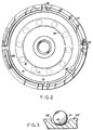
- FIG. 3 a partial showing of a modification of the high tensile ball and race which provides for limited rolling horizontal (radial) action is shown.
- FIG. 1 was described as having the high tensile balls roll in a groove of the bearing race which has a circular or circular arc shape in cross section of a somewhat larger radius than the radius of the high tensile balls to permit transverse or horizontal limited motion.
- FIG. 3 shows a modification in which the sectional shape of the groove for the balls is a portion of an ellipse.
- a bearing race 23' has therein a groove 25' that extends beyond the high tensile ball 21.
- FIG. 4 a single squeeze film chamber damping pad is shown which, in almost all respects, is similar to the outer damping chamber construction of FIG. 1.
- the changes involve an element 40' analogous to element 40 in FIG. 1, except that it is not cup shaped, but is rather a solid block that fits within the cavity of a cup shaped element 11', (which in this instance is not formed with a centrally projecting piston 14).
- the inner element 40' of FIG. 4 is recessed at the bottom to receive a ball bearing assembly 19, which is also retained in a recess 17 in the surface 16.
- the single squeeze film gap disclosed in FIG. 4 is formed and operates like the outer squeeze film gap in FIG. 1 and is achieved by eliminating the upwardly projecting piston 14 of FIG. 1 and instead substituting a solid block element 40' which is machined in just the way element 40 was in FIG. 1 at the bottom to receive the ball bearing assembly 19.
- the inner element 40' has a load bearing upper surface 41' and in each of the damping pads in FIG. 1 and FIG. 4, an axial bolt hole 50 provides for use of bolts or other fastening means to secure the damping pad when mounted for supported machinery.
- a modified damping pad is shown of simplified construction in accordance with the invention. It is shown constructed as a single squeeze film chamber cup and piston unit modified, however, by construction which permits utilizing the ball bearing assembly held in the recesses formed in the inner and outer damper elements as part of the squeeze film area.
- a cup shaped outer element 51 is dimensioned to receive a generally cylindrical piston shaped inner element 52 dimensioned to provide, when centered in the cavity of element 51 the parallel walls which form a circular squeeze film gap 53 defining the single squeeze film chamber.
- a ball bearing assembly 19 of the type described in FIG. 1 has lower and upper races 23 and 24 with especially enlarged grooves 25 and 26, as previously described.
- the difference in action of the FIG. 5 embodiment derives essentially from a manner in which the bearing assembly 19 is recessed into the retaining spaces in the outer element 51 and inner element 52. Referring to the right end portion of the bearing shown in FIG. 5 the subtle difference in mounting the bearing assembly and the effect of the change will be described.
- elements 51 and 52 are dimensioned to provide a squeeze film gap 53 between their inner and outer surfaces, respectively.
- This relationship holds true to and including the end face 56 of the upper race 24 which is opposed to the inner wall of outer element 51.
- This condition is achieved by forming the recesses to receive the bearing assembly in the inner element 52 at the periphery which forms the outer surface and, hence, end face 56 is part of the squeeze film gap walls.
- the recess in the lower corner of inner element 52 is rectangular to receive upper race 24 and reaches to the peripheral wall of the squeeze film gap.
- the upper race 24 is so positioned by virtue of a projecting shoulder 54 at the inner end of the recess which projects the race 24 in line with the inner surface of the squeeze film gap.
- the recess for the lower race 23 is formed solely by a shoulder 55 projecting from the inner wall of the outer element 51.
- the width of the projecting shoulders 54 and 55 is the same as that of the squeeze film gap 53, which positions the outer face of race 24 in gap forming relation to the inner wall of element 51, the outer face of race 24 being designated 56.
- the face 57 of lower race 23 forms a gap relation to the recess face 58 of element 52. Since the respective ends of races 23 and 24 are now positioned to continue the vibration absorbing gap whether positioned relative to the inner surface of element 51 or the outer surface (recessed) of element 52, the presence of the ball bearing assembly does not significantly reduce the area of active squeeze film gap.
- FIG. 5 Two screw plugs 61 and 62 may be provided for filling the squeeze film gap and exhausting air when squeeze film liquid is applied to fill the gap. Another feature is the elimination of the O-rings with the upper end of the squeeze film gap being sealed by elastomer material 63. Screw plugs 61 and 62 can be eliminated by filling the gap with oil from the top before sealing with elastomer 63.
- threaded bore hole 64 capable of receiving mating threaded bolts for securing the machine tool through the upper surface 65 to provide the load supporting contact with the inner element 52.
- known self leveling intermediate contact elements 66, 67, or other expedients may be used to properly position the load on the damping pad.
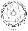
- FIG. 6 the general arrangement of the cup and piston elements, respectively, are shown similar to FIG. 1.
- the cup element 71 has a bottom wall that is adapted to receive high tensile roller bearing cylindrical rollers 73, which, as shown in FIG. 7, are constrained by grooves to roll in a single direction.
- the rollers 73 are distributed for uniform weight bearing as shown in circular plan view in FIG. 7.
- the squeeze film action is between the inner wall of cup element 71 and the outer wall of cylindrical piston element 72. Since the vibratory motion would be confined in the direction of rolling of the rollers 73 (which is shown vertical in Fig.
- the effective squeeze film action would occur primarily at the top and bottom positions (12 o'clock and 6 o'clock positions) of the annular squeeze film gap shown in FIG. 7 with squeeze film activity along the annular squeeze film gap diminishing approximately according to the cosine of the angle counted in clockwise or counterclockwise direction from the 12 o'clock position as the 0° position.
Landscapes
- Engineering & Computer Science (AREA)
- General Engineering & Computer Science (AREA)
- Physics & Mathematics (AREA)
- Acoustics & Sound (AREA)
- Aviation & Aerospace Engineering (AREA)
- Mechanical Engineering (AREA)
- Support Of The Bearing (AREA)
- Transition And Organic Metals Composition Catalysts For Addition Polymerization (AREA)
- Rolling Contact Bearings (AREA)
- Fluid-Damping Devices (AREA)
- Vibration Prevention Devices (AREA)
Applications Claiming Priority (2)
| Application Number | Priority Date | Filing Date | Title |
|---|---|---|---|
| US21177398A | 1998-12-15 | 1998-12-15 | |
| US211773 | 1998-12-15 |
Publications (2)
| Publication Number | Publication Date |
|---|---|
| EP1010917A1 true EP1010917A1 (fr) | 2000-06-21 |
| EP1010917B1 EP1010917B1 (fr) | 2001-11-21 |
Family
ID=22788310
Family Applications (1)
| Application Number | Title | Priority Date | Filing Date |
|---|---|---|---|
| EP99123288A Expired - Lifetime EP1010917B1 (fr) | 1998-12-15 | 1999-11-30 | Amortisseur à haute puissance |
Country Status (4)
| Country | Link |
|---|---|
| EP (1) | EP1010917B1 (fr) |
| AT (1) | ATE209305T1 (fr) |
| DE (1) | DE69900712T2 (fr) |
| ES (1) | ES2168832T3 (fr) |
Cited By (1)
| Publication number | Priority date | Publication date | Assignee | Title |
|---|---|---|---|---|
| EP1548319A2 (fr) | 2003-12-23 | 2005-06-29 | Suspensiones Elasticas Del Norte, S.L. | Isolateur amortisseur de vibrations |
Families Citing this family (1)
| Publication number | Priority date | Publication date | Assignee | Title |
|---|---|---|---|---|
| US10161264B2 (en) | 2017-04-24 | 2018-12-25 | United Technologies Corporation | Helically actuated variable bearing damper |
Citations (4)
| Publication number | Priority date | Publication date | Assignee | Title |
|---|---|---|---|---|
| GB726791A (en) * | 1951-09-26 | 1955-03-23 | Houdaille Hershey Corp | Improvements in or relating to vibration dampers |
| DE2248439A1 (de) * | 1972-10-03 | 1974-04-25 | Motoren Turbinen Union | Vorrichtung zur weichen und elastischen lagerung hochtourig umlaufender wellen |
| EP0157352A2 (fr) * | 1984-03-29 | 1985-10-09 | Cincinnati Milacron Inc. | Amortisseur de machine |
| DE4223256A1 (de) * | 1992-07-15 | 1994-01-20 | Schaeffler Waelzlager Kg | Schwingungdämpfende Lagerstellmutter |
-
1999
- 1999-11-30 AT AT99123288T patent/ATE209305T1/de not_active IP Right Cessation
- 1999-11-30 EP EP99123288A patent/EP1010917B1/fr not_active Expired - Lifetime
- 1999-11-30 DE DE69900712T patent/DE69900712T2/de not_active Expired - Fee Related
- 1999-11-30 ES ES99123288T patent/ES2168832T3/es not_active Expired - Lifetime
Patent Citations (5)
| Publication number | Priority date | Publication date | Assignee | Title |
|---|---|---|---|---|
| GB726791A (en) * | 1951-09-26 | 1955-03-23 | Houdaille Hershey Corp | Improvements in or relating to vibration dampers |
| DE2248439A1 (de) * | 1972-10-03 | 1974-04-25 | Motoren Turbinen Union | Vorrichtung zur weichen und elastischen lagerung hochtourig umlaufender wellen |
| EP0157352A2 (fr) * | 1984-03-29 | 1985-10-09 | Cincinnati Milacron Inc. | Amortisseur de machine |
| CA1236812A (fr) * | 1984-03-29 | 1988-05-17 | John R. Hasz | Appui amortisseur et de mise de niveau pour machine |
| DE4223256A1 (de) * | 1992-07-15 | 1994-01-20 | Schaeffler Waelzlager Kg | Schwingungdämpfende Lagerstellmutter |
Cited By (1)
| Publication number | Priority date | Publication date | Assignee | Title |
|---|---|---|---|---|
| EP1548319A2 (fr) | 2003-12-23 | 2005-06-29 | Suspensiones Elasticas Del Norte, S.L. | Isolateur amortisseur de vibrations |
Also Published As
| Publication number | Publication date |
|---|---|
| ATE209305T1 (de) | 2001-12-15 |
| EP1010917B1 (fr) | 2001-11-21 |
| DE69900712T2 (de) | 2002-08-22 |
| ES2168832T3 (es) | 2002-06-16 |
| DE69900712D1 (de) | 2002-02-21 |
Similar Documents
| Publication | Publication Date | Title |
|---|---|---|
| US7625121B2 (en) | Bearing assembly and centering support structure therefor | |
| US5613781A (en) | Hanging spring supported squeeze film damping system for shaft bearing | |
| US5102237A (en) | Self positioning beam mounted bearing and bearing and shaft assembly including the same | |
| CN1143408A (zh) | 滚珠在锥形区中的隔震支承 | |
| JP4121947B2 (ja) | ジャーナル軸受装置 | |
| US5125754A (en) | Multi-deflection pad hydrodynamic thrust and journal bearings having a modular construction | |
| US3549220A (en) | Low-stress ball bearings | |
| WO2001057408A1 (fr) | Mécanisme de palier à patins oscillants | |
| KR20210087530A (ko) | 구조물의 감쇠 진동용 매스 댐퍼, 이러한 매스 댐퍼를 갖는 구조물, 및 매스 댐퍼의 고유 진동수를 조정하는 방법 | |
| US3073654A (en) | Bearing assembly | |
| US3554619A (en) | Bearing support | |
| US6955467B2 (en) | Seismic isolation bearing assembly with a frame unit for supporting a machine body thereon | |
| EP0495074A1 (fr) | Paliers hydrodynamiques ayant des patins montes sur support et ensembles palier hermetiques comprenant lesdits paliers. | |
| EP1010917B1 (fr) | Amortisseur à haute puissance | |
| US3427080A (en) | Reciprocating bearing assembly having roller-bearing wheels on a bearing rod | |
| GB2085102A (en) | Isolating or Damping Load or Vibration | |
| US4161237A (en) | Vibration absorber for rotating body | |
| US8256966B2 (en) | Roller bearing arrangement | |
| JPH034145Y2 (fr) | ||
| EP2622236B1 (fr) | Palier flexible | |
| JPS62151638A (ja) | 粘性せん断抵抗を利用した回転式振動減衰装置 | |
| KR200208779Y1 (ko) | 탄성받침용 가이드 구조 | |
| RU2016278C1 (ru) | Подшипник качения | |
| SU1548544A1 (ru) | Упругодемпферный сегментный подшипник скольжени | |
| JP2850986B2 (ja) | スパイラルグルーブ式スラスト軸受の自動調芯機構 |
Legal Events
| Date | Code | Title | Description |
|---|---|---|---|
| PUAI | Public reference made under article 153(3) epc to a published international application that has entered the european phase |
Free format text: ORIGINAL CODE: 0009012 |
|
| 17P | Request for examination filed |
Effective date: 20000414 |
|
| AK | Designated contracting states |
Kind code of ref document: A1 Designated state(s): AT BE CH CY DE DK ES FI FR GB GR IE IT LI LU MC NL PT SE |
|
| AX | Request for extension of the european patent |
Free format text: AL;LT;LV;MK;RO;SI |
|
| AKX | Designation fees paid |
Free format text: AT BE CH CY DE DK ES FI FR GB GR IE IT LI LU MC NL PT SE |
|
| GRAG | Despatch of communication of intention to grant |
Free format text: ORIGINAL CODE: EPIDOS AGRA |
|
| 17Q | First examination report despatched |
Effective date: 20010726 |
|
| GRAG | Despatch of communication of intention to grant |
Free format text: ORIGINAL CODE: EPIDOS AGRA |
|
| GRAH | Despatch of communication of intention to grant a patent |
Free format text: ORIGINAL CODE: EPIDOS IGRA |
|
| GRAH | Despatch of communication of intention to grant a patent |
Free format text: ORIGINAL CODE: EPIDOS IGRA |
|
| GRAA | (expected) grant |
Free format text: ORIGINAL CODE: 0009210 |
|
| AK | Designated contracting states |
Kind code of ref document: B1 Designated state(s): AT BE CH CY DE DK ES FI FR GB GR IE IT LI LU MC NL PT SE |
|
| PG25 | Lapsed in a contracting state [announced via postgrant information from national office to epo] |
Ref country code: NL Free format text: LAPSE BECAUSE OF FAILURE TO SUBMIT A TRANSLATION OF THE DESCRIPTION OR TO PAY THE FEE WITHIN THE PRESCRIBED TIME-LIMIT Effective date: 20011121 Ref country code: GR Free format text: LAPSE BECAUSE OF FAILURE TO SUBMIT A TRANSLATION OF THE DESCRIPTION OR TO PAY THE FEE WITHIN THE PRESCRIBED TIME-LIMIT Effective date: 20011121 Ref country code: FI Free format text: LAPSE BECAUSE OF FAILURE TO SUBMIT A TRANSLATION OF THE DESCRIPTION OR TO PAY THE FEE WITHIN THE PRESCRIBED TIME-LIMIT Effective date: 20011121 Ref country code: CY Free format text: LAPSE BECAUSE OF NON-PAYMENT OF DUE FEES Effective date: 20011121 |
|
| REF | Corresponds to: |
Ref document number: 209305 Country of ref document: AT Date of ref document: 20011215 Kind code of ref document: T |
|
| PG25 | Lapsed in a contracting state [announced via postgrant information from national office to epo] |
Ref country code: MC Free format text: LAPSE BECAUSE OF NON-PAYMENT OF DUE FEES Effective date: 20011130 Ref country code: LU Free format text: LAPSE BECAUSE OF NON-PAYMENT OF DUE FEES Effective date: 20011130 Ref country code: IE Free format text: LAPSE BECAUSE OF FAILURE TO SUBMIT A TRANSLATION OF THE DESCRIPTION OR TO PAY THE FEE WITHIN THE PRESCRIBED TIME-LIMIT Effective date: 20011130 |
|
| REG | Reference to a national code |
Ref country code: CH Ref legal event code: EP |
|
| REG | Reference to a national code |
Ref country code: IE Ref legal event code: FG4D |
|
| REG | Reference to a national code |
Ref country code: GB Ref legal event code: IF02 |
|
| PGFP | Annual fee paid to national office [announced via postgrant information from national office to epo] |
Ref country code: SE Payment date: 20020108 Year of fee payment: 3 |
|
| PGFP | Annual fee paid to national office [announced via postgrant information from national office to epo] |
Ref country code: BE Payment date: 20020109 Year of fee payment: 3 |
|
| PGFP | Annual fee paid to national office [announced via postgrant information from national office to epo] |
Ref country code: FR Payment date: 20020110 Year of fee payment: 3 |
|
| ET | Fr: translation filed | ||
| PGFP | Annual fee paid to national office [announced via postgrant information from national office to epo] |
Ref country code: ES Payment date: 20020125 Year of fee payment: 3 |
|
| PGFP | Annual fee paid to national office [announced via postgrant information from national office to epo] |
Ref country code: DE Payment date: 20020128 Year of fee payment: 3 |
|
| PG25 | Lapsed in a contracting state [announced via postgrant information from national office to epo] |
Ref country code: PT Free format text: LAPSE BECAUSE OF FAILURE TO SUBMIT A TRANSLATION OF THE DESCRIPTION OR TO PAY THE FEE WITHIN THE PRESCRIBED TIME-LIMIT Effective date: 20020221 Ref country code: DK Free format text: LAPSE BECAUSE OF FAILURE TO SUBMIT A TRANSLATION OF THE DESCRIPTION OR TO PAY THE FEE WITHIN THE PRESCRIBED TIME-LIMIT Effective date: 20020221 |
|
| REF | Corresponds to: |
Ref document number: 69900712 Country of ref document: DE Date of ref document: 20020221 |
|
| REG | Reference to a national code |
Ref country code: CH Ref legal event code: NV Representative=s name: E. BLUM & CO. PATENTANWAELTE |
|
| NLV1 | Nl: lapsed or annulled due to failure to fulfill the requirements of art. 29p and 29m of the patents act | ||
| REG | Reference to a national code |
Ref country code: ES Ref legal event code: FG2A Ref document number: 2168832 Country of ref document: ES Kind code of ref document: T3 |
|
| REG | Reference to a national code |
Ref country code: IE Ref legal event code: MM4A |
|
| PLBE | No opposition filed within time limit |
Free format text: ORIGINAL CODE: 0009261 |
|
| STAA | Information on the status of an ep patent application or granted ep patent |
Free format text: STATUS: NO OPPOSITION FILED WITHIN TIME LIMIT |
|
| 26N | No opposition filed | ||
| PG25 | Lapsed in a contracting state [announced via postgrant information from national office to epo] |
Ref country code: BE Free format text: LAPSE BECAUSE OF NON-PAYMENT OF DUE FEES Effective date: 20021130 Ref country code: AT Free format text: LAPSE BECAUSE OF NON-PAYMENT OF DUE FEES Effective date: 20021130 |
|
| PG25 | Lapsed in a contracting state [announced via postgrant information from national office to epo] |
Ref country code: SE Free format text: LAPSE BECAUSE OF NON-PAYMENT OF DUE FEES Effective date: 20021201 Ref country code: ES Free format text: LAPSE BECAUSE OF NON-PAYMENT OF DUE FEES Effective date: 20021201 |
|
| BERE | Be: lapsed |
Owner name: *AIR LOC SCHREPFER A.G. Effective date: 20021130 |
|
| PG25 | Lapsed in a contracting state [announced via postgrant information from national office to epo] |
Ref country code: DE Free format text: LAPSE BECAUSE OF NON-PAYMENT OF DUE FEES Effective date: 20030603 |
|
| EUG | Se: european patent has lapsed | ||
| PG25 | Lapsed in a contracting state [announced via postgrant information from national office to epo] |
Ref country code: FR Free format text: LAPSE BECAUSE OF NON-PAYMENT OF DUE FEES Effective date: 20030731 |
|
| REG | Reference to a national code |
Ref country code: FR Ref legal event code: ST |
|
| PG25 | Lapsed in a contracting state [announced via postgrant information from national office to epo] |
Ref country code: LI Free format text: LAPSE BECAUSE OF NON-PAYMENT OF DUE FEES Effective date: 20031130 Ref country code: GB Free format text: LAPSE BECAUSE OF NON-PAYMENT OF DUE FEES Effective date: 20031130 Ref country code: CH Free format text: LAPSE BECAUSE OF NON-PAYMENT OF DUE FEES Effective date: 20031130 |
|
| REG | Reference to a national code |
Ref country code: ES Ref legal event code: FD2A Effective date: 20031213 |
|
| REG | Reference to a national code |
Ref country code: CH Ref legal event code: PL |
|
| GBPC | Gb: european patent ceased through non-payment of renewal fee |
Effective date: 20031130 |
|
| PG25 | Lapsed in a contracting state [announced via postgrant information from national office to epo] |
Ref country code: IT Free format text: LAPSE BECAUSE OF NON-PAYMENT OF DUE FEES Effective date: 20051130 |