EP1010920A2 - Dispositif et procédé de commande du rapport d'engrenage pour une transmission continue - Google Patents
Dispositif et procédé de commande du rapport d'engrenage pour une transmission continue Download PDFInfo
- Publication number
- EP1010920A2 EP1010920A2 EP99124764A EP99124764A EP1010920A2 EP 1010920 A2 EP1010920 A2 EP 1010920A2 EP 99124764 A EP99124764 A EP 99124764A EP 99124764 A EP99124764 A EP 99124764A EP 1010920 A2 EP1010920 A2 EP 1010920A2
- Authority
- EP
- European Patent Office
- Prior art keywords
- speed ratio
- continuously variable
- variable transmission
- torque
- toroidal continuously
- Prior art date
- Legal status (The legal status is an assumption and is not a legal conclusion. Google has not performed a legal analysis and makes no representation as to the accuracy of the status listed.)
- Withdrawn
Links
- 230000005540 biological transmission Effects 0.000 title claims abstract description 128
- 238000000034 method Methods 0.000 title claims description 9
- 238000006073 displacement reaction Methods 0.000 claims abstract description 37
- 230000007935 neutral effect Effects 0.000 claims description 39
- 230000003247 decreasing effect Effects 0.000 claims description 3
- 230000007423 decrease Effects 0.000 description 28
- 230000008859 change Effects 0.000 description 18
- 238000010586 diagram Methods 0.000 description 10
- 239000000446 fuel Substances 0.000 description 9
- 238000002347 injection Methods 0.000 description 9
- 239000007924 injection Substances 0.000 description 9
- 230000009467 reduction Effects 0.000 description 8
- 230000000994 depressogenic effect Effects 0.000 description 5
- 238000010276 construction Methods 0.000 description 2
- ATJFFYVFTNAWJD-UHFFFAOYSA-N Tin Chemical compound [Sn] ATJFFYVFTNAWJD-UHFFFAOYSA-N 0.000 description 1
- 238000013459 approach Methods 0.000 description 1
- 230000000694 effects Effects 0.000 description 1
- 230000005489 elastic deformation Effects 0.000 description 1
- 230000006870 function Effects 0.000 description 1
- 238000012986 modification Methods 0.000 description 1
- 230000004048 modification Effects 0.000 description 1
- 238000012545 processing Methods 0.000 description 1
- 230000004044 response Effects 0.000 description 1
- 238000012546 transfer Methods 0.000 description 1
Images









Classifications
-
- F—MECHANICAL ENGINEERING; LIGHTING; HEATING; WEAPONS; BLASTING
- F16—ENGINEERING ELEMENTS AND UNITS; GENERAL MEASURES FOR PRODUCING AND MAINTAINING EFFECTIVE FUNCTIONING OF MACHINES OR INSTALLATIONS; THERMAL INSULATION IN GENERAL
- F16H—GEARING
- F16H61/00—Control functions within control units of change-speed- or reversing-gearings for conveying rotary motion ; Control of exclusively fluid gearing, friction gearing, gearings with endless flexible members or other particular types of gearing
- F16H61/66—Control functions within control units of change-speed- or reversing-gearings for conveying rotary motion ; Control of exclusively fluid gearing, friction gearing, gearings with endless flexible members or other particular types of gearing specially adapted for continuously variable gearings
- F16H61/664—Friction gearings
- F16H61/6648—Friction gearings controlling of shifting being influenced by a signal derived from the engine and the main coupling
-
- F—MECHANICAL ENGINEERING; LIGHTING; HEATING; WEAPONS; BLASTING
- F16—ENGINEERING ELEMENTS AND UNITS; GENERAL MEASURES FOR PRODUCING AND MAINTAINING EFFECTIVE FUNCTIONING OF MACHINES OR INSTALLATIONS; THERMAL INSULATION IN GENERAL
- F16H—GEARING
- F16H37/00—Combinations of mechanical gearings, not provided for in groups F16H1/00 - F16H35/00
- F16H37/02—Combinations of mechanical gearings, not provided for in groups F16H1/00 - F16H35/00 comprising essentially only toothed or friction gearings
- F16H37/06—Combinations of mechanical gearings, not provided for in groups F16H1/00 - F16H35/00 comprising essentially only toothed or friction gearings with a plurality of driving or driven shafts; with arrangements for dividing torque between two or more intermediate shafts
- F16H37/08—Combinations of mechanical gearings, not provided for in groups F16H1/00 - F16H35/00 comprising essentially only toothed or friction gearings with a plurality of driving or driven shafts; with arrangements for dividing torque between two or more intermediate shafts with differential gearing
- F16H37/0833—Combinations of mechanical gearings, not provided for in groups F16H1/00 - F16H35/00 comprising essentially only toothed or friction gearings with a plurality of driving or driven shafts; with arrangements for dividing torque between two or more intermediate shafts with differential gearing with arrangements for dividing torque between two or more intermediate shafts, i.e. with two or more internal power paths
- F16H37/084—Combinations of mechanical gearings, not provided for in groups F16H1/00 - F16H35/00 comprising essentially only toothed or friction gearings with a plurality of driving or driven shafts; with arrangements for dividing torque between two or more intermediate shafts with differential gearing with arrangements for dividing torque between two or more intermediate shafts, i.e. with two or more internal power paths at least one power path being a continuously variable transmission, i.e. CVT
- F16H2037/088—Power-split transmissions with summing differentials, with the input of the CVT connected or connectable to the input shaft
-
- F—MECHANICAL ENGINEERING; LIGHTING; HEATING; WEAPONS; BLASTING
- F16—ENGINEERING ELEMENTS AND UNITS; GENERAL MEASURES FOR PRODUCING AND MAINTAINING EFFECTIVE FUNCTIONING OF MACHINES OR INSTALLATIONS; THERMAL INSULATION IN GENERAL
- F16H—GEARING
- F16H61/00—Control functions within control units of change-speed- or reversing-gearings for conveying rotary motion ; Control of exclusively fluid gearing, friction gearing, gearings with endless flexible members or other particular types of gearing
- F16H61/66—Control functions within control units of change-speed- or reversing-gearings for conveying rotary motion ; Control of exclusively fluid gearing, friction gearing, gearings with endless flexible members or other particular types of gearing specially adapted for continuously variable gearings
- F16H2061/6604—Special control features generally applicable to continuously variable gearings
- F16H2061/6614—Control of ratio during dual or multiple pass shifting for enlarged ratio coverage
-
- F—MECHANICAL ENGINEERING; LIGHTING; HEATING; WEAPONS; BLASTING
- F16—ENGINEERING ELEMENTS AND UNITS; GENERAL MEASURES FOR PRODUCING AND MAINTAINING EFFECTIVE FUNCTIONING OF MACHINES OR INSTALLATIONS; THERMAL INSULATION IN GENERAL
- F16H—GEARING
- F16H37/00—Combinations of mechanical gearings, not provided for in groups F16H1/00 - F16H35/00
- F16H37/02—Combinations of mechanical gearings, not provided for in groups F16H1/00 - F16H35/00 comprising essentially only toothed or friction gearings
- F16H37/06—Combinations of mechanical gearings, not provided for in groups F16H1/00 - F16H35/00 comprising essentially only toothed or friction gearings with a plurality of driving or driven shafts; with arrangements for dividing torque between two or more intermediate shafts
- F16H37/08—Combinations of mechanical gearings, not provided for in groups F16H1/00 - F16H35/00 comprising essentially only toothed or friction gearings with a plurality of driving or driven shafts; with arrangements for dividing torque between two or more intermediate shafts with differential gearing
- F16H37/0833—Combinations of mechanical gearings, not provided for in groups F16H1/00 - F16H35/00 comprising essentially only toothed or friction gearings with a plurality of driving or driven shafts; with arrangements for dividing torque between two or more intermediate shafts with differential gearing with arrangements for dividing torque between two or more intermediate shafts, i.e. with two or more internal power paths
- F16H37/084—Combinations of mechanical gearings, not provided for in groups F16H1/00 - F16H35/00 comprising essentially only toothed or friction gearings with a plurality of driving or driven shafts; with arrangements for dividing torque between two or more intermediate shafts with differential gearing with arrangements for dividing torque between two or more intermediate shafts, i.e. with two or more internal power paths at least one power path being a continuously variable transmission, i.e. CVT
- F16H37/086—CVT using two coaxial friction members cooperating with at least one intermediate friction member
-
- F—MECHANICAL ENGINEERING; LIGHTING; HEATING; WEAPONS; BLASTING
- F16—ENGINEERING ELEMENTS AND UNITS; GENERAL MEASURES FOR PRODUCING AND MAINTAINING EFFECTIVE FUNCTIONING OF MACHINES OR INSTALLATIONS; THERMAL INSULATION IN GENERAL
- F16H—GEARING
- F16H61/00—Control functions within control units of change-speed- or reversing-gearings for conveying rotary motion ; Control of exclusively fluid gearing, friction gearing, gearings with endless flexible members or other particular types of gearing
- F16H61/66—Control functions within control units of change-speed- or reversing-gearings for conveying rotary motion ; Control of exclusively fluid gearing, friction gearing, gearings with endless flexible members or other particular types of gearing specially adapted for continuously variable gearings
- F16H61/664—Friction gearings
Definitions
- This invention relates to control of a non-finite speed ratio transmission device for vehicles using a toroidal continuously variable transmission.
- USP5,935,039 discloses a non-finite speed ratio transmission device which combines a toroidal continuously variable transmission, a fixed speed ratio transmission and a planetary gear unit in order to obtain a speed ratio range larger than the toroidal continuously variable transmission.
- Tokkai Hei 10-267117 published by the Japanese Patent Office in 1997 discloses a controller which controls the creep torque applied to a drive wheel at low vehicle speed according to the operating state of the brake in such an non-finite speed ratio transmission device.
- This controller assigns a step number obtained by subtracting or adding a fixed amount from a step number corresponding to a geared neutral position GNP to a step motor, and increases or decreases a difference of oil pressure acting on a trunnion from two directions using a relief valve.
- the geared neutral position GNP is a rotating position of the step motor at which the output rotation speed of the non-finite speed ratio transmission device becomes zero.
- the response characteristics of oil pressure control generally decline when the temperature of the oil transmitting the oil pressure decreases.
- this invention provides a speed ratio controller for use with a non-finite speed ratio transmission device of a vehicle.
- the transmission device comprises a toroidal continuously variable transmission which causes a speed ratio to vary according to a gyration angle variation of a power roller gripped between an input disk and output disk.
- the power roller vares the gyration angle according to a displacement of a supporting member which supports the power roller.
- the transmission device further comprises a fixed speed ratio transmission which varies a rotation speed of the input disk with a fixed speed ratio, and a planetary gear unit which varies a rotation direction of a final output shaft according to a relation between a rotation output speed of the toroidal continuously variable transmission and a rotation output speed of the fixed speed ratio transmission.
- the speed ratio controller comprises a hydraulic cylinder which displaces the supporting member according to a supplied hydraulic pressure, a control valve which supplies a hydraulic pressure to the hydraulic cylinder according to a displacement position thereof, an actuator which displaces the control valve according to a command signal, a feedback member which connects the supporting member and control valve and feeds back the displacement of the supporting member to the control valve by causing the control valve to displace in the reverse direction to the displacement direction due to the actuator, a sensor which detects a running state of the vehicle, a sensor which detects the speed ratio of the toroidal continuously variable transmission, and a microprocessor.
- the microprocessor is programmed to determine whether or not the vehicle running state corresponds to a predetermined state, calculate a new command signal based on a predetermined creep torque and the speed ratio of the toroidal continuously variable transmission when the vehicle running state corresponds to the predetermined state, and output the new command signal to the actuator.
- This invention also provides a method for controlling a speed ratio of a non-finite speed ratio transmission device of a vehicle.
- the transmission device comprises a toroidal continuously variable transmission which causes a speed ratio to vary according to a gyration angle variation of a power roller gripped between an input disk and output disk, the power roller varying the gyration angle according to a displacement of a supporting member which supports the power roller, a hydraulic cylinder which displaces the supporting member according to a supplied hydraulic pressure, a control valve which supplies a hydraulic pressure to the hydraulic cylinder according to a displacement position thereof, an actuator which displaces the control valve according to a command signal, a feedback member which connects the supporting member and control valve and feeds back the displacement of the supporting member to the control valve by causing the control valve to displace in the reverse direction to the displacement direction due to the actuator, a fixed speed ratio transmission which varies a rotation speed of the input disk with a fixed speed ratio, and a planetary gear unit which varies a rotation direction of a final
- the method comprises detecting a running state of the vehicle, detecting the speed ratio of the toroidal continuously variable transmission, determining whether or not the vehicle running state corresponds to a predetermined state, calculating a new command signal based on a predetermined creep torque and the speed ratio of the toroidal continuously variable transmission when the vehicle running state corresponds to the predetermined state, and outputting the new command signal to the actuator.
- a non-finite speed ratio transmission device for a vehicle comprises an input shaft 1, toroidal continuously variable transmission (abbreviated hereafter as CVT) 2, reduction gear unit 3 as a fixed speed ratio transmission, planetary gear unit 5 and final output shaft 6.
- CVT continuously variable transmission
- reduction gear unit 3 as a fixed speed ratio transmission
- planetary gear unit 5 final output shaft 6.
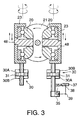
- the CVT 2 is provided with two toroidal units. Each toroidal unit comprises an input disk 21, an output disk 22 and a pair of power rollers 20 gripped therebetween.
- the input disks 1 are joined to the input shaft 1, and the input shaft 1 is joined to the output shaft of an engine of the vehicle, not shown.
- the rotation of the output disks 22 is transmitted to a CVT output shaft 4 via a sprocket 2A, chain 40 and sprocket 4A.
- the power roller 20 is supported by a trunnion 23.
- the trunnion 23 is driven in the up / down direction of the figure by a hydraulic cylinder 30.
- the hydraulic cylinder 30 comprises a piston 31 fixed to the trunnion 23, and oil chambers 30A, 30B formed above and below the piston 31.
- the trunnion 23 displaces in an axial direction according to the differential pressure of the oil chambers 30A, 30B, and varies the contact position between the power roller 20, input disk 21 and output disk 22. This changes the balance of forces around the axis of the trunnion 23 exerted by these disks on the power roller 20, and the power roller 20 performs a rotational displacement together with the trunnion 23 around the axis of the trunnion 23. This is referred to as gyration angle variation of the power roller 20.
- the oil chamber 30A of one of the trunnions 23 is disposed above the piston 31, and the oil chamber 30A of the other trunnion 23 is provided underneath the piston 31.
- the oil chamber 30B of one of the trunnions 23 is disposed above the piston 31, and the oil chamber 30B of the other trunnion 23 is provided underneath the piston 31.
- the same oil pressure is supplied to both of the oil chambers 30A, and the same oil pressure is supplied to both of the oil chambers 30B. Due to this arrangement of the oil chambers 30A, 30B, the two trunnions 23 are driven in mutually opposite directions.
- the CVT 2 altogether comprises four of the trunnions 23, but as shown in
- a precess cam 35 is attached to one of them.
- the oil pressure of the oil chambers 30A, 30B is supplied from a shift control valve 46 shown in
- the precess cam 35 feeds back the rotation angle of the trunnion 23, i.e., a gyration angle ⁇ of the power roller 20 and the axial displacement of the trunnion 23 to the control valve.
- a cam groove 35A inclined in a circumferential direction is formed on the outer circumference of the precess cam 35, and one end of an L-shaped feedback link 38 engages with the cam groove 35A.
- the feedback link 38 is supported free to pivot on a pivot shaft 39, one end being engaged with the cam groove 35A and the other end being connected with one end of a speed change link 37.
- a speed change link 37 is connected to the edge of a spool 46S of the shift control valve 46, and the other end of the speed change link 37 located on the opposite side of the connecting part with the feedback link 38 is connected to a step motor 36. Due to this arrangement, the speed change link 37 displaces the spool 46S in an axial direction according to the drive of the step motor 36.
- the displacement of the spool 46S causes the rotational displacement and the axial displacement of the trunnion 23.
- the precess cam 35, feedback link 38 and speed change link 37 feed back these displacements to the spool 46S by displacing the spool 46S in the opposite direction.
- the spool 46S is maintained in a position wherein the displacement of the step motor 36 and the precess cam 35 are balanced.
- the precess cam 35, speed change link 37 and feedback link 38 are arranged to return the spool 46S to a neutral position when the CVT 2 reaches a speed ratio corresponding to the step number of the step motor 36.
- the meaning of neutral position in this context is a position wherein inflow and outflow of oil to and from the oil chambers 30A and 30B is blocked.
- the precess cam 35, feedback link 38 and speed change link 37 are referred to as mechanical feedback members.
- the CVT output shaft 4 is joined to a sun gear 5A of the planetary gear unit 5. It is also joined to the final output shaft 6 via a direct mode clutch 10.
- the reduction gear unit 3 comprises a gear 3A, gear 3B and gear output shaft 3C which rotate together with the input shaft 1.
- the gear 3A is meshed with the gear 3B, and the gear 3B is joined to the gear output shaft 3C via a power circulation mode clutch 9.
- the gear output shaft 3C is joined to a planet carder 5B which holds planet gears of the planetary gear unit 5.
- a ring gear 5C of the planetary gear unit 5 is joined to the final output shaft 6. The rotation of the final output shaft 6 is transmitted to the drive wheels 11A, 11B of the vehicle via a transmission output gear 7, final gear 12 and differential gear unit 8.
- the drive of the drive wheels 11A, 11B is performed in two kinds of power transfer mode, i.e., a power circulation mode wherein the power circulation mode clutch 9 is engaged and the direct mode clutch 10 is released, or a direct mode wherein the power circulation mode clutch 9 is released and the direct mode clutch 10 is engaged.
- the rotation speed of the planet carrier 5B is equal to a value obtained by dividing the engine rotation speed by the reduction ratio of the reduction gear unit 3.
- the reduction ratio of the reduction gear unit 3 is a fixed value.
- the rotation speed of the sun gear 5A is equal to a value obtained by dividing the engine rotation speed by the speed ratio ic of the continuously variable transmission 2.
- the rotation direction of the sun gear 5A and planet carrier 5B is always fixed.
- the rotation direction of the ring gear 5C which is joined to the final output shaft 6 varies according to the ratio of the rotation speed of the planet carrier 5B, and the rotation speed of the sun gear 5C. In other words, it varies according to the ratio of the engine rotation speed and the rotation speed of the CVT output shaft 4, i.e., according to the speed ratio ic of the continuously variable transmission 2.
- the point at which the rotation direction changes corresponds to a geared neutral position GNP shown in Fig. 9.
- the ring gear 5C i.e., the final output shaft 6, does not rotate, and the vehicle stops.
- the input disk 21 and output disk 22 of the CVT 2 are rotating relative to each other, but torque is not transmitted between the output disk 22 and final output shaft 6, so torque is not transmitted between the input disk 21 and output disk 22 either.
- the ring gear 5C rotates in the forward travel direction of the vehicle and if the speed ratio ic decreases to less than the GNP, the ring gear 5C rotates in the reverse direction. That is, in the power circulation mode, vehicle forward and reverse are changed over by controlling the speed ratio ic .
- the final speed ratio ii of the non-finite speed ratio continuously variable transmission decreases.
- the inverse 1/ ii of the final speed ratio ii increases, as shown in Fig. 9.
- the power circulation mode shifts to the direct mode.
- the direct mode the rotation of the CVT output shaft 4 is directly transmitted to the final output shaft 6, so as the speed ratio ic of the continuously variable transmission 2 decreases, the final speed ratio ii of the non-finite speed ratio transmission device also decreases.
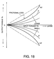
- the speed ratio ic decreases, the inverse 1/ ii increases as shown in Fig. 18.
- the final speed ratio ii of the non-finite speed ratio continuously variable transmission is largest when the vehicle starts. After the vehicle starts, it decreases as the vehicle speed increases.
- the speed ratio ic of the continuously variable transmission at this time first begins to increase up to a revolution synchronization point RSP, and after the power circulation mode changes over to the direct mode at the revolution synchronization point RSP, it begins to decrease.
- the speed ratio ic of the continuously variable transmission 2 varies in an opposite direction to when the vehicle is accelerating.
- the speed ratio ic becomes smaller than that of the geared neutral position GNP, and as the speed ratio ic decreases, the absolute value of 1/ ii increases in the negative direction. That is, the final speed ratio ii approaches 0.
- the speed ratio ic corresponding to the geared neutral position GNP will be referred to as ic0
- the gyration angle ⁇ of the power roller 20 at that time will be referred to as ⁇ 0 .
- the microprocessor 80 comprises a central processing unit (CPU), read-only memory (ROM), random access memory (RAM), and an input/output interface (I/O interface).
- CPU central processing unit
- ROM read-only memory
- RAM random access memory
- I/O interface input/output interface
- signals from an input shaft rotation speed sensor 81 which detects a rotation speed Ni of the input shaft 1, CVT output shaft rotation speed sensor 82 which detects a rotation speed Nco of the CVT output shaft 4, vehicle speed sensor 83 which detects the vehicle speed VSP from the rotation speed of the final output shaft 6, a depression amount signal from an accelerator pedal depression sensor 86 and a brake signal showing if a vehicle brake pedal is depressed as detected by a brake switch 87, are respectively input into the microprocessor 80.
- the rotation speed Ni of the input shaft 1 is equal to the rotation speed Ne of the engine.
- the oil pressure device comprises a pressure regulator 100 which converts an oil pressure supplied from an oil pump 120, to a predetermined line pressure PL .
- the pressure regulator 100 performs this pressure adjustment according to a signal pressure produced by a solenoid valve 90, and supplies the line pressure PL to a line pressure circuit 101.
- a shift control valve 46 which controls the supply direction and amount of oil to the hydraulic cylinders 30 which drive the trunnions 23, is connected to the line pressure circuit 101.
- the shift control valve 46 is provided with a supply port 46P connected to the line pressure circuit 101, speed ratio increase port 46L connected to the oil chambers 30A of the hydraulic cylinders 30, speed ratio decrease port 46H connected to the oil chambers 30B of the hydraulic cylinders 30, and two drain ports 46D.
- the line pressure PL is supplied from the supply port 46P to the speed ratio increase port 46L or the speed ratio decrease port 46H according to the position of the spool 46S in the axial direction, the other of the ports 46L and 46H being connected to the drain port 46D.
- step motor 36 drives the speed change link 37 from the neutral position towards the upper part of Fig. 4 so as to obtain a given target speed ratio
- the spool 46S which is displaced in the same direction connects the supply port 46P to the speed ratio increase port 46L, and connects the speed ratio decrease port 46H to the drain port 46D.
- the contact positions of the power rollers 20, and input disk 21 and output disk 22 shift, and the power rollers 20 and trunnion 23 are caused to rotate around the axis of the trunnion 23 due to a component force in the horizontal direction of the figure exerted by the input disk 21 and output disk 22 on the power rollers 20.
- This rotational displacement causes a variation of the gyration angle ⁇ in a direction tending to increase the speed ratio ic .
- the speed ratio ic is a value obtained by dividing the rotation speed Ni of the input shaft 1 by the rotation speed Nco of the CVT output shaft 4.
- the spool 46S reaches the neutral position when the gyration angle ⁇ of the power rollers 20 coincides with the target speed ratio, and the hydraulic cylinders 30 stop driving the pistons 31.
- step motor 36 drives the spool 46S towards the lower part of Fig. 4 from the neutral position, the spool 46S connects the supply port 46P to the speed ratio reduction port 46H, and connects the speed ratio increase port 46L to the drain port 46D.
- the spool 46S which had moved down, displaces upwards toward the neutral position.
- the spool 46S reaches the neutral position and the hydraulic cylinders 30 stop driving the pistons 31.
- the microprocessor 80 calculates the step number STEP of the step motor 36 based on the target value of the speed ratio ic of the continuously variable transmission 2.
- the target value of the speed ratio ic is calculated as follows.
- the final speed ratio ii of the non -finite speed ratio transmission device is first determined based on the accelerator pedal depression amount and vehicle speed VSP by the same technique as in the calculation of target speed ratio of a continuously variable transmission disclosed by Tokkai Sho 61-105347 published in 1986 by the Japanese Patent Office.
- the microprocessor 80 looks up the corresponding target speed ratio of the continuously variable transmission 2 from the map of Fig. 9, and calculates the step number STEP corresponding to target speed change ratio.
- This map is stored beforehand by the microprocessor 80. In this map, the minimum value of the step number STEP corresponds to the maximum speed ratio of the continuously variable transmission 2, and the gyration angle ⁇ of the power roller 20 is a minimum.
- the maximum value of the step number STEP corresponds to the minimum speed ratio of the continuously variable transmission 2, and the gyration angle ⁇ of the power roller 20 is a maximum.
- the target value of the differential pressure of the oil chambers 30A and 30B may also be calculated instead of the speed ratio ic , and the step number STEP determined according to this target value.
- the microprocessor 80 controls the speed ratio ic of the continuously variable transmission 2.
- a solenoid valve 91 which engages and releases the direct mode clutch 10 and a solenoid valve 92 which engages and releases the power circulation mode clutch 9, are connected to the line pressure circuit 101.
- the solenoid valve 91 produces a signal pressure which increases or decreases the line pressure PL of the line pressure circuit 101 according to a signal from the microprocessor 80, and supplies it to a control valve 93.
- the control valve 93 supplies the line pressure PL to the direct mode clutch 10 via a manual valve 60 according to the increase of signal pressure and engages the direct mode clutch 10.
- the solenoid valve 92 produces a signal pressure by decreasing the line pressure PL of the line pressure circuit 101 according to a signal from the microprocessor 80, and supplies it to a control valve 94.
- the control valve 94 supplies the line pressure PL to the power circulation mode clutch 9 according to the increase of signal pressure via a manual valve 60 and a shuttle valve 121, and engages the power circulation mode clutch 9. On the other hand, when the signal pressure from the solenoid valve 92 decreases, the control valve 94 releases the power circulation mode clutch 9 by connecting it to a drain.
- the change-over of drive force transmission modes and control of the speed ratio ic of the continuously variable transmission 2 are performed as described above.
- the microprocessor 80 also performs control of the transmitted torque of the continuously variable transmission 2 so that a desirable creep torque is obtained in the vicinity of the neutral position GNP of the power circulation mode.
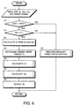
- This routine is performed at an interval of,for example. 10 milliseconds.
- step S1 the vehicle speed VSP detected by the vehicle speed sensor 83, the rotation spee d Ni of the input shaft 1 detected by the input shaft rotation speed sensor 81, the rotation speed Nco of the CVT output shaft 4 detected by the CVT output shaft rotation speed sensor 82, the accelerator pedal depression amount Acc detected by the accelerator pedal depression sensor 86 and a brake signal generated by the brake switch 87 are read.
- step S2 it is determined whether or not the vehicle speed VSP is less than a predetermined speed VSP0 .
- the predetermined speed VSP0 is a value near zero, so if the vehicle speed VSP is less than the predetermined speed VSP0 , it means that the speed ratio ic of the continuously variable transmission 2 is near the geared neutral position GNP of the power circulation mode.
- the routine proceeds to a step S3, and it is determined if the accelerator pedal depression amount Acc is zero. When Acc is zero, the routine performs creep torque control in a step
- VSP is not less than VSP0 in the step S2 or the accelerator pedal depression Acc is not zero in the step S3, after performing the usual control of the speed ratio ic in a step S9, the routine is terminated.
- the present real speed ratio ic is calculated from the rotation speed Ni of the input shaft 1 and the rotation speed Nco of the CVT output shaft 4 by the following equation (1).
- the final speed ratio ii of the non-finite speed ratio transmission device can also be used instead of the speed ratio ic of the CVT 2.
- the geared neutral position GNP as the rotation speed of the final output shaft 6 is 0, it is difficult to grasp the exact final speed ratio ii .
- both the input shaft 1 and the CVT output shaft 4 are rotating even at the geared neutral position GNP as long as the engine is running, a slight fluctuation of the speed ratio ic can be grasped accurately.
- a target creep torque Tc is set.
- the target creep torque Tc is set to different values respectively for when the vehicle is moving forward and when it is reversing. Forward and reverse motion of the vehicle can be distinguished from a selector lever attached to the non-finite speed ratio transmission device.
- the vehicle when the selector lever selects the ordinary forward running range (D) or forward sports running range (Ds), the vehicle is moving or about to move forward, and when the selector lever selects the reverse range (R), the vehicle is reversing or about to reverse.
- D ordinary forward running range
- Ds forward sports running range
- R reverse range
- different values of the target creep torque Tc are set depending on whether or not the brake pedal of the vehicle is depressed. For example, when the vehicle is moving forward and the brake is not depressed, a large creep torque T3 is read. When the brake is depressed, a small creep torque T1 is read. Also when the vehicle is reversing, the different creep torques - T3 and - T1 are read in the same way depending on the operating state of the brake.
- a target step number of the step motor 36 required to generate the target creep torque Tc is computed by referring to a map of creep torque To shown in Fig. 7 prestored by the microprocessor 80.
- the thick solid line is a line on which the creep torque To of the final output shaft 6 is 0, i.e., a state where drive force does not act on the vehicle.
- a point B in Fig. 7 denotes the target step number when the brake pedal is depressed and the vehicle is not moving while the selector lever is in a forward travel range.
- the target step number to obtain the target creep torque varies, because the speed ratio of the CVT 2 is no longer equal to ic0 .
- the required output torque To of the final output shaft 6 is set to a different value. Therefore, in the map of Fig. 7, the target step number St is determined based on the present real speed ratio ic and the required output torque To of the final output shaft 6.
- step S7 the difference of the target step number St and the present step number S0 is calculated as a command step number Sx .
- the present step number S0 is equal to the step number output to the step motor 36 on the immediately preceding occasion when me routine was performed.
- step S8 the command step number Sx is output to the step motor 36, and the routine is terminated.
- the target creep torque Tc is set to the creep torque T1 for forward motion
- step number of the step motor 36 will decrease. Due to the decrease of step number, the step motor 36 displaces the spool 46S of the shift control valve 46 in the direction which increases the speed ratio ic of the CVT 2. Consequently, the oil chambers 30A rise to higher pressure than the oil chambers 30B and the pistons 31 exert a drive force on the trunnions 23 in the direction of the solid line of Fig. 3.
- the speed ratio ic of the continuously variable transmission 2 is forcibly held at the speed ratio ic0 which corresponds to the geared neutral position GNP. That is, even if the pistons 31 exert a force on the trunnions 23 in the direction of the solid line of Fig. 3, the gyration angle of the power roller 20 does not vary.
- the power roller 20 which tends to vary the gyration angle ⁇ in a direction which would increase the speed ratio, causes a torque to act on the output disk 22 in the direction of deceleration.
- the vehicle starts moving forward when the speed ratio of the continuously variable transmission 2 increases, as can be seen from Fig. 9.
- the deceleration torque which acts on the output disk 22 is therefore a torque tending to rotate the final output shaft 6 in the forward travel direction, i.e., it acts as a creep torque in the forward travel direction.
- an arbitrary creep torque To can be generated by driving the step motor 36 with a step number STEP according to the target creep torque Tc .
- a phenomenon known as a torque shift occurs according to the fluctuation of input torque, as disclosed in Tokkai Hei 8-338492 published in 1996 by the Japanese Patent Office.
- a deviation occurs in the correspondence relation between the real gyration angle ⁇ of the power roller 20, and the step number STEP output to the step motor 36.
- a torque shift during normal running occurs due to the fluctuation of an input torque, but in a non-finite speed ratio transmission, when the speed ratio ic of the CVT 2 is forcibly held at a fixed value as mentioned above, a torque shift also occurs when it is attempted to displace the trunnion 23 in the axial direction.
- a deviation of the speed ratio ic in the decreasing direction increases creep torque in the forward travel direction of the vehicle
- a deviation of the speed ratio ic in the increase direction increases the creep torque in the reverse direction
- the spool 46S of the shift control valve 46 returns to the center position, and even if the target speed ratio corresponding to the step number STEP of the step motor 36 is apparently obtained, the real speed ratio does not reach the target speed change ratio. Hence, a torque corresponding to this deviation acts on the output disk 22.
- the oil pressures of the oil chambers 30A, 30B are maintained as they are.
- creep torque can continue to be generated by maintaining the shift control valve 46 in the neutral state.
- Creep torque can still be generated by an oil pressure according to the target creep torque Tc even when the oil pressure applied to the piston is fed back electronically when the continuously variable transmission does not comprise mechanical feedback members using a precess cam, as in the speed ratio continuously variable transmission disclosed in USP5,935,039 of the aforesaid prior art.
- it is difficult to ensure precise control of the creep torque when oil temperature is low.
- the non-finite speed ratio transmission provided with a mechanical feedback member can perform feedback control of creep torque by a mechanical system without performing electronic feedback, the precision of controlling creep torque does not decline even at low oil temperature. Moreover, by considering the effect of the above-mentioned torque shift beforehand and determining the step number STEP according to the target creep torque Tc , the creep torque can be controlled with high precision.
- step number STEP of the step motor 36 and the speed ratio ic of the continuously variable transmission 2 will be described in the state where the driver depresses the brake and prevents rotation of the final output shaft 6 near the geared neutral position GNP of the power circulation mode of this non-finite speed ratio transmission device.
- Fig. 8A if the step number STEP of the step motor 36 decreases from S0 to Sf , the pressure of the oil chamber 30A rises above that of the oil chamber 30B, and the trunnion 23 displaces in the axial direction to the upper part of Fig. 3.
- the rotation speed of the final output shaft 6 is limited to 0 due to the braking of the driver, and the gyration angle ⁇ of the power roller 20 corresponding to geared neutral position GNP cannot vary from ⁇ 0 , so the speed ratio ic is still ic0.
- step number STEP shifts from point A to point Af of Fig. 8A, so the output torque To of the final output shaft 6 increases from 0 to + Tb .
- the output torque To of the final output shaft 6 can be increased to + Tb and creep torque can be generated while maintaining the speed ratio ic at ic0 corresponding to the geared neutral position GNP.
- step number STEP of the step motor 36 reaches Sf , provided that the stop state of the vehicle is maintained, the gyration angle ⁇ of the power roller 20 is still ⁇ 0 , so the mechanical feedback members comprising the precess cam 35 of the continuously variable transmission 2 only transmit the axial displacement of the trunnion 23 to the spool 46F.
- the vehicle will stop at a point C at which the output torque coincides with the running resistance. This is due to idle rotation speed control of the engine, not shown.
- the creep torque To increases from the point A to the point Af in the figure, the engine load increases, and the fuel injection amount of the engine increases.
- the engine load also decreases as the creep torque To decreases, and the fuel injection amount of the engine decreases until the drive resistance and engine output of the vehicle are balanced. Consequently, the forward motion of the vehicle stops.
- an arbitrary creep torque To can be generated in a range from the point A to a point Ar at which the braking torque - Tb is balanced by varying the step number STEP of the step motor 35 in the range from S0 to Sr , as in the case where the step number STEP is made to vary from S0 to Sf .
- the target creep torque Tc can be obtained easily and surely regardless of oil temperature by driving the step motor 36 to the step number STEP which corresponds to the target creep torque Tc .
- this non-finite speed ratio transmission device also always performs precise speed ratio control regardless of oil temperature during normal running where the speed ratio ic of the CVT 2 varies largely.
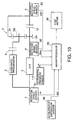
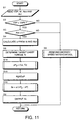
- the non-finite speed ratio transmission device comprises a differential pressure sensor 110 shown in Fig. 10 which detects a differential pressure ⁇ P of the oil chambers 30A and 30B of the cylinder 30.
- the microprocessor 80 performs electronic feedback control so that the target creep torque Tc according to the differential pressure ⁇ P may be realized.
- steps S14 - S16 are provided instead of the steps S6 and S7.
- a target differential pressure ⁇ P 0 is computed from the required output torque To of the final output shaft 6 and the present speed ratio ic by looking up a map shown in Fig. 12.
- the required output torque To is equal to the target creep torque Tc .
- the target differential pressure ⁇ P 0 is given by the following equation (2), where the oil pressure of the oil chamber 30A is Plo and the oil pressure of the oil chamber 30B is Phi .
- ⁇ P 0 Phi - Plo
- the solid line gives a target differential pressure ⁇ P 0 corresponding to the output torque
- the target differential pressure ⁇ P 0 is found using the line ic ⁇ ic0 shown by the dotted line.
- the target differential pressure ⁇ P 0 is found using the line ic > ic0 shown by another dotted line.
- plural lines are actually used depending on the speed ratio ic for finding the target differential pressure ⁇ P 0 , both for the case ic ⁇ ic0 and the case ic > ic0 .
- a step S15 the present differential pressure ⁇ P detected by the differential pressure sensor 110 is read.
- the command step number St of the step motor 36 is calculated by the following equation (3) based on the deviation of between the target differential pressure ⁇ P 0 and the present differential pressure ⁇ P .
- Sx ⁇ ( ⁇ P 0 - ⁇ P )
- the command step number Sx may also be found by using the map shown in Fig. 13 instead of using the above-mentioned function.
- This map specifies the relation of the step number STEP of the step motor 36 to the differential pressure ⁇ P near the geared neutral position GNP.
- the differential pressure ⁇ P increases in the positive direction in the figure
- the corresponding step number STEP increases, and conversely, if the differential pressure ⁇ P increases in the negative direction, the step number STEP also increases in the negative direction.
- the increase of differential pressure ⁇ P in the positive direction corresponds to the increase of the oil pressure Phi of the oil chamber 30B
- increase of the differential pressure in the negative direction corresponds to the increase of the oil pressure Plo of oil chamber 30A.
- the command step number Sx is found according to the deviation between the present differential pressure ⁇ P and target differential pressure ⁇ P 0 . In the last step S8, the command step number Sx is output and the routine is terminated.
- the step motor 36 in the vicinity of the geared neutral position GNP of the power circulation mode, the step motor 36 is run so as to achieve the differential pressure ⁇ P 0 according to the target creep torque Tc while the present speed ratio ic is maintained.
- the mechanical feedback members control the creep torque generated by the CVT 2 to the target creep torque Tc for the command step number Sx with high precision regardless of the oil temperature, as in the aforesaid first embodiment.
- the creep torque is controlled based on a torque ratio t of the non-finite speed ratio transmission device instead of using the map of Fig. 7 as in the aforesaid first embodiment.
- the microprocessor 80 controls the non -finite speed ratio transmission device in association with an engine controller 85, as shown in Fig. 14.
- the target creep torque Tc is equal to the required output torque To of the final output shaft 6, the target creep torque Tc can be realized by controlling the torque ratio t of the non-finite speed ratio transmission device relative to the input torque Ti .
- the input torque Ti of the input shaft 1 is equal to the output torque Te of the engine, not shown.
- Various methods have been proposed to detect or estimate the output torque Te of the engine. For example, a method is known whereby the engine torque Te is found from the fuel injection amount Tp read from the engine control controller 85, and the fuel injection amount Tp is taken as the engine torque Te.
- the fuel injection amount Tp is considered to have the same significance the engine torque Te .
- the engine control controller 85 performs idle rotation speed control of the engine so that the engine rotation speed Ne is a predetermined idle rotation speed when the vehicle is in the stop state. If the creep torque To is altered, the load of the engine also varies, so the fuel injection amount Tp is also varied to maintain the predetermined idle rotation speed.
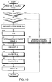
- the flowchart of Fig. 15 corresponds to the flowchart of Fig. 6 of the aforesaid first embodiment, and shows the routine for controlling the creep torque performed by the microprocessor 80.
- step S20 the vehicle speed VSP, rotation speed Ni of the input shaft 1, rotation speed Nco of the CVT output shaft 4 and fuel injection amount input from the engine control controller 85, are read.
- the fuel injection amount Tp is set equal to the input torque Ti of the speed change ratio non-finite transmission device.
- step 5 the target creep torque Tc is read as in the aforesaid first embodiment.
- a target speed ratio icr is found which corresponds to the target torque ratio tr by referring to a map of Fig. 16.
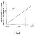
- step S27 the step number STEP of the step motor 36 corresponding to the target speed ratio icr is calculated as the command step number Sx from the map of usual speed ratio control of the first embodiment shown in Fig. 5.
- command step number Sx is output to the step motor 36 in the step S8, and the routine is terminated.
- the step motor 36 is run so as to obtain the target torque ratio tr according to the target speed ratio ic while maintaining the present creep torque. Further, the mechanical feedback members control the creep torque generated by the CVT 2 to the target creep torque Tc relative to the command step number Sx to a high precision regardless of the oil temperature, as in the aforesaid first embodiment.
- the fuel injection amount Tp of the engine was used as the input torque Ti of the non-finite speed ratio transmission device, so the engine load is correctly reflected in the control of the creep torque, and the precision of creep torque control is improved.
- Fig. 17 shows a fourth embodiment of this invention.
- This embodiment replaces the map of Fig. 16 of the aforesaid third embodiment by a map specifying the relation between the output torque To of the final output shaft 6 and the speed ratio ic with the input torque Ti of the input shaft 1 as a parameter.
- the remaining features of the construction are the same as those of the aforesaid third embodiment.
- the calculation of the target torque ratio tr of the step S25 of the flowchart of Fig. 15 is omitted, the target creep torque Tc which was read in the step S5 is taken as the output torque To of the final output shaft 6, and this is applied to the map of Fig. 17 together with the input torque Ti found in the step S23.
- the number of steps of the control routine is reduced, so the computing load of the microprocessor 80 is less.
- Fig. 18 shows a fifth embodiment of this invention.
- This embodiment gives an alternative to the map of Fig. 17 of the aforesaid fourth embodiment.
- the power circulation mode clutch 9 is disposed between the gear output shaft 3B and the carrier 5B, but it can be disposed in any position between the input shaft 1 and transmission output gear 7 of the final output shaft 6.
- it may be provided between the ring gear 5C and final output shaft 6, between the input shaft 1 and the gear 3A of the reduction gear unit 3, or midway along the CVT output shaft 4 connected to the sun gear 5A.
- the speed change link 37 was connected to the spool 46S, step motor 36 and feedback link 38, but instead of the speed change link 37, the spool 46S may be connected directly to the step motor 36, and a sleeve which displaces relative to the spool 46S may be interposed between the spool 46S and the ports, and connected to the feedback link 38.
- the spool 46S and sleeve connect the speed ratio increase port 46L and speed ratio decrease port 46H to the supply port 46P and drain port 46D according to the relative displacement position of the spool 46S and sleeve.
- the target creep torque Tc was set to a value which changes with the operating state of the brake, but the target creep torque Tc may also be made to vary according to the road gradient or the running state of the vehicle.
Landscapes
- Engineering & Computer Science (AREA)
- General Engineering & Computer Science (AREA)
- Mechanical Engineering (AREA)
- Control Of Transmission Device (AREA)
- Friction Gearing (AREA)
Applications Claiming Priority (2)
| Application Number | Priority Date | Filing Date | Title |
|---|---|---|---|
| JP35627798 | 1998-12-15 | ||
| JP35627798 | 1998-12-15 |
Publications (2)
| Publication Number | Publication Date |
|---|---|
| EP1010920A2 true EP1010920A2 (fr) | 2000-06-21 |
| EP1010920A3 EP1010920A3 (fr) | 2001-09-12 |
Family
ID=18448229
Family Applications (1)
| Application Number | Title | Priority Date | Filing Date |
|---|---|---|---|
| EP99124764A Withdrawn EP1010920A3 (fr) | 1998-12-15 | 1999-12-13 | Dispositif et procédé de commande du rapport d'engrenage pour une transmission continue |
Country Status (2)
| Country | Link |
|---|---|
| US (1) | US6312357B1 (fr) |
| EP (1) | EP1010920A3 (fr) |
Cited By (3)
| Publication number | Priority date | Publication date | Assignee | Title |
|---|---|---|---|---|
| WO2001021981A3 (fr) * | 1999-09-20 | 2002-02-14 | Transmission Technologies Corp | Commande double mode pour transmission a changement de vitesse continu du type a entrainement toroidal |
| CN104565258A (zh) * | 2015-01-19 | 2015-04-29 | 山东交通学院 | 一种滚轮式复合汽车变速器 |
| US9821658B1 (en) | 2016-09-12 | 2017-11-21 | Hyundai Motor Company | Method for controlling vehicle creep driving |
Families Citing this family (13)
| Publication number | Priority date | Publication date | Assignee | Title |
|---|---|---|---|---|
| JP3458830B2 (ja) * | 2000-07-21 | 2003-10-20 | 日産自動車株式会社 | 変速比無限大無段変速機の制御装置 |
| JP4101450B2 (ja) * | 2000-09-27 | 2008-06-18 | ジヤトコ株式会社 | 無段変速機の発進時変速制御装置 |
| JP3680746B2 (ja) * | 2001-03-09 | 2005-08-10 | 日産自動車株式会社 | 変速比無限大無段変速機の制御装置 |
| JP3794295B2 (ja) * | 2001-07-25 | 2006-07-05 | 日産自動車株式会社 | トロイダル型無段変速機の変速制御装置 |
| JP3980352B2 (ja) * | 2001-12-28 | 2007-09-26 | ジヤトコ株式会社 | トロイダル型無段変速機のトルクシフト補償装置 |
| US7035727B2 (en) | 2002-05-29 | 2006-04-25 | Visteon Global Technologies, Inc. | Apparatus and method of controlling vehicle creep control under braking |
| US6931316B2 (en) * | 2002-06-05 | 2005-08-16 | Nissan Motor Co., Ltd. | Toroidal continuously variable transmission control apparatus |
| JP4378991B2 (ja) * | 2003-04-10 | 2009-12-09 | 日本精工株式会社 | 無段変速装置 |
| JP3665060B2 (ja) * | 2003-07-04 | 2005-06-29 | 本田技研工業株式会社 | ハイブリッド車両の制御装置 |
| DE102005057809A1 (de) * | 2005-12-03 | 2007-06-06 | Zf Friedrichshafen Ag | Verfahren zur Schaltsteuerung eines automatisierten Kraftfahrzeug-Schaltgetriebes |
| JP5253786B2 (ja) * | 2007-03-20 | 2013-07-31 | ヤマハ発動機株式会社 | 変速装置、それを備えたパワーユニット、車両、変速装置の制御装置および変速装置の制御方法 |
| JP5273121B2 (ja) * | 2010-10-19 | 2013-08-28 | 株式会社デンソー | 発進支援装置 |
| KR102496636B1 (ko) * | 2016-11-25 | 2023-02-07 | 현대자동차주식회사 | 하이브리드 차량의 타행주행 제어 장치 및 그 방법 |
Family Cites Families (19)
| Publication number | Priority date | Publication date | Assignee | Title |
|---|---|---|---|---|
| JPS61105351A (ja) * | 1984-10-30 | 1986-05-23 | Nissan Motor Co Ltd | 変速機の制御装置 |
| JPS61105347A (ja) | 1984-10-30 | 1986-05-23 | Nissan Motor Co Ltd | 無段変速機の油圧制御装置 |
| JPH0678781B2 (ja) * | 1987-02-18 | 1994-10-05 | ダイハツ工業株式会社 | トロイダル形無段変速機のクリ−プ制御装置 |
| JP2687576B2 (ja) * | 1989-05-02 | 1997-12-08 | 日産自動車株式会社 | 無段変速機の変速制御装置 |
| JP3376763B2 (ja) | 1995-06-15 | 2003-02-10 | 日産自動車株式会社 | トロイダル型無段変速機の制御装置 |
| JP3446413B2 (ja) * | 1995-08-03 | 2003-09-16 | 日産自動車株式会社 | 変速比無限大無段変速機のトルク伝達力制御装置 |
| DE19631281C2 (de) * | 1995-08-23 | 2003-01-02 | Luk Gs Verwaltungs Kg | Verfahren zum Steuern des Anhaltvorgangs eines mit einem automatischen Getriebe mit stufenlos veränderbarer Übersetzung ausgerüsteten Kraftfahrzeugs |
| JP3579981B2 (ja) | 1995-09-20 | 2004-10-20 | 日産自動車株式会社 | 変速比無限大無段変速機 |
| US6146308A (en) * | 1996-10-03 | 2000-11-14 | Aisin Aw Co., Ltd. | Creep torque control of infinitely variable transmission |
| JP3475678B2 (ja) * | 1996-10-09 | 2003-12-08 | アイシン・エィ・ダブリュ株式会社 | 無段変速機 |
| US5888160A (en) * | 1996-11-13 | 1999-03-30 | Nsk Ltd. | Continuously variable transmission |
| DE19703544A1 (de) * | 1997-01-31 | 1998-08-06 | Zahnradfabrik Friedrichshafen | Reibradgetriebe |
| JPH10252875A (ja) * | 1997-03-10 | 1998-09-22 | Nissan Motor Co Ltd | 変速比無限大無段変速機の油圧制御装置 |
| JP3724175B2 (ja) * | 1997-03-22 | 2005-12-07 | マツダ株式会社 | トロイダル式無段変速機の制御装置 |
| JPH10267117A (ja) | 1997-03-24 | 1998-10-09 | Mazda Motor Corp | トロイダル式無段変速機の制御装置 |
| DE19836558C2 (de) * | 1997-08-12 | 2003-03-13 | Nsk Ltd | Stufenlos verstellbares Toroidgetriebesystem |
| JP3855536B2 (ja) * | 1998-06-15 | 2006-12-13 | 日産自動車株式会社 | 無段変速機の変速制御装置 |
| US6168547B1 (en) * | 1998-07-24 | 2001-01-02 | Nissan Motor Co., Ltd. | Line pressure control device for automatic transmission |
| JP2000046135A (ja) * | 1998-07-28 | 2000-02-18 | Nissan Motor Co Ltd | トロイダル型無段変速機の変速制御装置 |
-
1999
- 1999-12-13 EP EP99124764A patent/EP1010920A3/fr not_active Withdrawn
- 1999-12-14 US US09/460,503 patent/US6312357B1/en not_active Expired - Fee Related
Cited By (5)
| Publication number | Priority date | Publication date | Assignee | Title |
|---|---|---|---|---|
| WO2001021981A3 (fr) * | 1999-09-20 | 2002-02-14 | Transmission Technologies Corp | Commande double mode pour transmission a changement de vitesse continu du type a entrainement toroidal |
| US6663532B1 (en) | 1999-09-20 | 2003-12-16 | Transmisiones Tsp, S. A., De, C.V. | Dual strategy control for a toroidal drive type continuously variable transmission |
| CN104565258A (zh) * | 2015-01-19 | 2015-04-29 | 山东交通学院 | 一种滚轮式复合汽车变速器 |
| CN104565258B (zh) * | 2015-01-19 | 2017-01-25 | 山东交通学院 | 一种滚轮式复合汽车变速器 |
| US9821658B1 (en) | 2016-09-12 | 2017-11-21 | Hyundai Motor Company | Method for controlling vehicle creep driving |
Also Published As
| Publication number | Publication date |
|---|---|
| US6312357B1 (en) | 2001-11-06 |
| EP1010920A3 (fr) | 2001-09-12 |
Similar Documents
| Publication | Publication Date | Title |
|---|---|---|
| US6312357B1 (en) | Speed ratio controller and control method of non-finite speed ratio transmission device | |
| US6569052B2 (en) | Control of infinitely variable transmission | |
| US6659901B2 (en) | Infinite speed ratio continuously variable transmission | |
| EP1134110A2 (fr) | Dispositif de commande de la force motrice d'un véhicule avec transmission à variation continue | |
| US4867732A (en) | Control device for belt-and-pulley type continuously variable transmission for a vehicle | |
| US7517299B2 (en) | Transmission control system | |
| US6436001B1 (en) | Speed change controller for infinite speed ratio transmission | |
| US6829528B1 (en) | Control system and control method for automatic transmission | |
| US6287232B1 (en) | Non-finite speed ratio continuously variable transmission device | |
| US7192372B2 (en) | Hydraulic pressure sensor failure control system for belt-type continuously variable transmission | |
| US5368530A (en) | Apparatus for controlling change ratio of stepless transmission | |
| US6317672B1 (en) | Controller for infinite speed ratio transmission | |
| US6409625B1 (en) | Controller of toroidal continuously variable transmission | |
| EP1089022B1 (fr) | Commande de la pression de ligne pour un variateur continu de vitesse | |
| US6168547B1 (en) | Line pressure control device for automatic transmission | |
| US6505139B1 (en) | Speed ratio control device for vehicle | |
| JP3991528B2 (ja) | 無段変速機のための発進クラッチ制御装置 | |
| US6370468B1 (en) | Speed ratio control device for vehicle | |
| US6398691B1 (en) | Speed ratio control device | |
| US20070197323A1 (en) | Hydraulic pressure control device for vehicle continuously variable transmission | |
| JP3275709B2 (ja) | 無段変速機の変速制御装置 | |
| US6347270B1 (en) | Speed ratio control device | |
| JP4304745B2 (ja) | パワートレインの制御装置 | |
| JP2000179674A (ja) | パワートレインの制御装置 | |
| JP4253891B2 (ja) | パワートレインの制御装置 |
Legal Events
| Date | Code | Title | Description |
|---|---|---|---|
| PUAI | Public reference made under article 153(3) epc to a published international application that has entered the european phase |
Free format text: ORIGINAL CODE: 0009012 |
|
| 17P | Request for examination filed |
Effective date: 19991213 |
|
| AK | Designated contracting states |
Kind code of ref document: A2 Designated state(s): AT BE CH CY DE DK ES FI FR GB GR IE IT LI LU MC NL PT SE Kind code of ref document: A2 Designated state(s): DE FR GB |
|
| AX | Request for extension of the european patent |
Free format text: AL;LT;LV;MK;RO;SI |
|
| PUAL | Search report despatched |
Free format text: ORIGINAL CODE: 0009013 |
|
| AK | Designated contracting states |
Kind code of ref document: A3 Designated state(s): AT BE CH CY DE DK ES FI FR GB GR IE IT LI LU MC NL PT SE |
|
| AX | Request for extension of the european patent |
Free format text: AL;LT;LV;MK;RO;SI |
|
| AKX | Designation fees paid |
Free format text: DE FR GB |
|
| 17Q | First examination report despatched |
Effective date: 20021212 |
|
| STAA | Information on the status of an ep patent application or granted ep patent |
Free format text: STATUS: THE APPLICATION IS DEEMED TO BE WITHDRAWN |
|
| 18D | Application deemed to be withdrawn |
Effective date: 20031107 |