EP1010925B1 - Système de commande à vérins pour la section auxiliare d'une boíte de vitesses composite - Google Patents
Système de commande à vérins pour la section auxiliare d'une boíte de vitesses composite Download PDFInfo
- Publication number
- EP1010925B1 EP1010925B1 EP99124369A EP99124369A EP1010925B1 EP 1010925 B1 EP1010925 B1 EP 1010925B1 EP 99124369 A EP99124369 A EP 99124369A EP 99124369 A EP99124369 A EP 99124369A EP 1010925 B1 EP1010925 B1 EP 1010925B1
- Authority
- EP
- European Patent Office
- Prior art keywords
- valve
- bore
- piston
- range
- splitter
- Prior art date
- Legal status (The legal status is an assumption and is not a legal conclusion. Google has not performed a legal analysis and makes no representation as to the accuracy of the status listed.)
- Expired - Lifetime
Links
- 230000005540 biological transmission Effects 0.000 title claims description 43
- 150000001875 compounds Chemical class 0.000 title claims description 17
- 238000007789 sealing Methods 0.000 claims description 33
- 239000012530 fluid Substances 0.000 claims description 28
- 230000009347 mechanical transmission Effects 0.000 claims description 8
- 230000001276 controlling effect Effects 0.000 claims description 6
- 230000001105 regulatory effect Effects 0.000 claims description 6
- 238000005260 corrosion Methods 0.000 claims description 5
- 230000007797 corrosion Effects 0.000 claims description 5
- 230000008878 coupling Effects 0.000 claims description 4
- 238000010168 coupling process Methods 0.000 claims description 4
- 238000005859 coupling reaction Methods 0.000 claims description 4
- 230000004044 response Effects 0.000 claims description 3
- XAGFODPZIPBFFR-UHFFFAOYSA-N aluminium Chemical compound [Al] XAGFODPZIPBFFR-UHFFFAOYSA-N 0.000 claims description 2
- 229910052782 aluminium Inorganic materials 0.000 claims description 2
- 238000001914 filtration Methods 0.000 claims description 2
- 239000000463 material Substances 0.000 claims description 2
- 230000007246 mechanism Effects 0.000 description 11
- 230000008859 change Effects 0.000 description 5
- 230000000712 assembly Effects 0.000 description 4
- 238000000429 assembly Methods 0.000 description 4
- 230000007935 neutral effect Effects 0.000 description 4
- 239000000356 contaminant Substances 0.000 description 3
- 229910001018 Cast iron Inorganic materials 0.000 description 2
- 230000000694 effects Effects 0.000 description 2
- 229910001369 Brass Inorganic materials 0.000 description 1
- 239000010951 brass Substances 0.000 description 1
- 238000011109 contamination Methods 0.000 description 1
- 230000008676 import Effects 0.000 description 1
- 239000000314 lubricant Substances 0.000 description 1
- 230000009467 reduction Effects 0.000 description 1
Images




Classifications
-
- F—MECHANICAL ENGINEERING; LIGHTING; HEATING; WEAPONS; BLASTING
- F16—ENGINEERING ELEMENTS AND UNITS; GENERAL MEASURES FOR PRODUCING AND MAINTAINING EFFECTIVE FUNCTIONING OF MACHINES OR INSTALLATIONS; THERMAL INSULATION IN GENERAL
- F16H—GEARING
- F16H61/00—Control functions within control units of change-speed- or reversing-gearings for conveying rotary motion ; Control of exclusively fluid gearing, friction gearing, gearings with endless flexible members or other particular types of gearing
- F16H61/70—Control functions within control units of change-speed- or reversing-gearings for conveying rotary motion ; Control of exclusively fluid gearing, friction gearing, gearings with endless flexible members or other particular types of gearing specially adapted for change-speed gearing in group arrangement, i.e. with separate change-speed gear trains arranged in series, e.g. range or overdrive-type gearing arrangements
- F16H61/705—Control functions within control units of change-speed- or reversing-gearings for conveying rotary motion ; Control of exclusively fluid gearing, friction gearing, gearings with endless flexible members or other particular types of gearing specially adapted for change-speed gearing in group arrangement, i.e. with separate change-speed gear trains arranged in series, e.g. range or overdrive-type gearing arrangements using hydraulic and mechanical control means
-
- F—MECHANICAL ENGINEERING; LIGHTING; HEATING; WEAPONS; BLASTING
- F16—ENGINEERING ELEMENTS AND UNITS; GENERAL MEASURES FOR PRODUCING AND MAINTAINING EFFECTIVE FUNCTIONING OF MACHINES OR INSTALLATIONS; THERMAL INSULATION IN GENERAL
- F16H—GEARING
- F16H61/00—Control functions within control units of change-speed- or reversing-gearings for conveying rotary motion ; Control of exclusively fluid gearing, friction gearing, gearings with endless flexible members or other particular types of gearing
- F16H61/02—Control functions within control units of change-speed- or reversing-gearings for conveying rotary motion ; Control of exclusively fluid gearing, friction gearing, gearings with endless flexible members or other particular types of gearing characterised by the signals used
- F16H61/0262—Control functions within control units of change-speed- or reversing-gearings for conveying rotary motion ; Control of exclusively fluid gearing, friction gearing, gearings with endless flexible members or other particular types of gearing characterised by the signals used the signals being hydraulic
- F16H61/0276—Elements specially adapted for hydraulic control units, e.g. valves
-
- F—MECHANICAL ENGINEERING; LIGHTING; HEATING; WEAPONS; BLASTING
- F16—ENGINEERING ELEMENTS AND UNITS; GENERAL MEASURES FOR PRODUCING AND MAINTAINING EFFECTIVE FUNCTIONING OF MACHINES OR INSTALLATIONS; THERMAL INSULATION IN GENERAL
- F16H—GEARING
- F16H61/00—Control functions within control units of change-speed- or reversing-gearings for conveying rotary motion ; Control of exclusively fluid gearing, friction gearing, gearings with endless flexible members or other particular types of gearing
- F16H61/26—Generation or transmission of movements for final actuating mechanisms
- F16H61/28—Generation or transmission of movements for final actuating mechanisms with at least one movement of the final actuating mechanism being caused by a non-mechanical force, e.g. power-assisted
- F16H61/30—Hydraulic or pneumatic motors or related fluid control means therefor
-
- F—MECHANICAL ENGINEERING; LIGHTING; HEATING; WEAPONS; BLASTING
- F16—ENGINEERING ELEMENTS AND UNITS; GENERAL MEASURES FOR PRODUCING AND MAINTAINING EFFECTIVE FUNCTIONING OF MACHINES OR INSTALLATIONS; THERMAL INSULATION IN GENERAL
- F16H—GEARING
- F16H61/00—Control functions within control units of change-speed- or reversing-gearings for conveying rotary motion ; Control of exclusively fluid gearing, friction gearing, gearings with endless flexible members or other particular types of gearing
- F16H61/02—Control functions within control units of change-speed- or reversing-gearings for conveying rotary motion ; Control of exclusively fluid gearing, friction gearing, gearings with endless flexible members or other particular types of gearing characterised by the signals used
- F16H61/0202—Control functions within control units of change-speed- or reversing-gearings for conveying rotary motion ; Control of exclusively fluid gearing, friction gearing, gearings with endless flexible members or other particular types of gearing characterised by the signals used the signals being electric
- F16H61/0251—Elements specially adapted for electric control units, e.g. valves for converting electrical signals to fluid signals
- F16H2061/0253—Details of electro hydraulic valves, e.g. lands, ports, spools or springs
-
- F—MECHANICAL ENGINEERING; LIGHTING; HEATING; WEAPONS; BLASTING
- F16—ENGINEERING ELEMENTS AND UNITS; GENERAL MEASURES FOR PRODUCING AND MAINTAINING EFFECTIVE FUNCTIONING OF MACHINES OR INSTALLATIONS; THERMAL INSULATION IN GENERAL
- F16H—GEARING
- F16H61/00—Control functions within control units of change-speed- or reversing-gearings for conveying rotary motion ; Control of exclusively fluid gearing, friction gearing, gearings with endless flexible members or other particular types of gearing
- F16H61/26—Generation or transmission of movements for final actuating mechanisms
- F16H61/28—Generation or transmission of movements for final actuating mechanisms with at least one movement of the final actuating mechanism being caused by a non-mechanical force, e.g. power-assisted
- F16H61/30—Hydraulic or pneumatic motors or related fluid control means therefor
- F16H2061/308—Modular hydraulic shift units, i.e. preassembled actuator units for select and shift movements adapted for being mounted on transmission casing
-
- F—MECHANICAL ENGINEERING; LIGHTING; HEATING; WEAPONS; BLASTING
- F16—ENGINEERING ELEMENTS AND UNITS; GENERAL MEASURES FOR PRODUCING AND MAINTAINING EFFECTIVE FUNCTIONING OF MACHINES OR INSTALLATIONS; THERMAL INSULATION IN GENERAL
- F16H—GEARING
- F16H2306/00—Shifting
- F16H2306/20—Timing of gear shifts
-
- Y—GENERAL TAGGING OF NEW TECHNOLOGICAL DEVELOPMENTS; GENERAL TAGGING OF CROSS-SECTIONAL TECHNOLOGIES SPANNING OVER SEVERAL SECTIONS OF THE IPC; TECHNICAL SUBJECTS COVERED BY FORMER USPC CROSS-REFERENCE ART COLLECTIONS [XRACs] AND DIGESTS
- Y10—TECHNICAL SUBJECTS COVERED BY FORMER USPC
- Y10T—TECHNICAL SUBJECTS COVERED BY FORMER US CLASSIFICATION
- Y10T137/00—Fluid handling
- Y10T137/8593—Systems
- Y10T137/86493—Multi-way valve unit
- Y10T137/86574—Supply and exhaust
- Y10T137/8667—Reciprocating valve
- Y10T137/86694—Piston valve
- Y10T137/8671—With annular passage [e.g., spool]
-
- Y—GENERAL TAGGING OF NEW TECHNOLOGICAL DEVELOPMENTS; GENERAL TAGGING OF CROSS-SECTIONAL TECHNOLOGIES SPANNING OVER SEVERAL SECTIONS OF THE IPC; TECHNICAL SUBJECTS COVERED BY FORMER USPC CROSS-REFERENCE ART COLLECTIONS [XRACs] AND DIGESTS
- Y10—TECHNICAL SUBJECTS COVERED BY FORMER USPC
- Y10T—TECHNICAL SUBJECTS COVERED BY FORMER US CLASSIFICATION
- Y10T74/00—Machine element or mechanism
- Y10T74/19—Gearing
- Y10T74/19219—Interchangeably locked
- Y10T74/19293—Longitudinally slidable
- Y10T74/19298—Multiple spur gears
- Y10T74/19326—Fluid operated
Definitions
- the present invention relates to a system for controlling the range and/or splitter shifts of an automated or semi-automated mechanical transmission.
- Compound change gear transmissions of the type having one or more auxiliary sections connected in series with a main transmission section are very well known in the prior art. Such transmissions are typically associated with heavy duty vehicles such as large trucks, tractor semi-trailers, and the like.
- main and auxiliary transmission sections connected in series the total number of available transmission ratios is generally equal to the product of the main and auxiliary section ratios.
- Auxiliary transmission sections may generally be characterized as range type, splitter type, or combined range and splitter type.
- range section ratio step or steps are greater than the total ratio coverage of the main transmission section and the main section is shifted progressively through its ratios in each range.
- the assignee's well known RT/RTO ROADRANGER transmissions include a "(5) ⁇ (2)" ten speed heavy duty range type transmission.
- the ratio steps of the splitter auxiliary section are less than the ratio steps of the main transmission section and each main section ratio is split, or subdivided, by the splitter section.
- both range and splitter type ratios are provided allowing the main section to be progressively shifted through its ratios in at least two ranges and also allowing the main section ratios to be split in at least one range.
- Assignee's well known RT/RTO 11613 and RT/RTO 14718 "Eaton Roadranger" transmissions are examples of a "(4 + 1) ⁇ (3)" thirteen-speed and a "(4 + 1) ⁇ (4)" eighteen-speed combined range/splitter type transmission.
- main and auxiliary sections are relative and that if the designations of the main and auxiliary sections are reversed, the type of auxiliary section (either range or splitter) will also be reversed. In other words, given what is conventionally considered a four-speed main section with two-speed range type auxiliary section, if the normally designated auxiliary is considered the main section, the normally designated main section would be considered a four-speed splitter type auxiliary section.
- the main transmission section of a compound transmission is that section which contains the largest (or at least no less) number of forward speed ratios, which allows selection of a neutral position, which contains the reverse ratio(s) and/or which is shifted (in manual or semiautomatic transmissions) by manipulation of a shift bar or shift rail or shift shaft/shift finger assembly as opposed to master/slave valve/cylinder arrangements or the like.
- EP 526 127 A discloses a range and splitter actuator control system according to the preamble of claim 1 comprising a control valve placed in the cover.
- EP 134 667 A discloses a shift valve with a flat sliding surface and a transverse bore.
- the main transmission section is typically shifted using a shift bar housing assembly, or a single shift shaft assembly, controlled by a manually operated shift lever.
- the auxiliary range section is generally shifted using a button or a switch which controls a remote slave valve/actuator mechanism.
- the range is shifted in response to switches which sense the position of the shift lever.
- the actuator mechanism typically includes a cylinder cover/valve assembly which directs pressurized fluid (air) to one side of the appropriate cylinder/piston while exhausting the opposite side.
- the pressurized fluid is supplied through a hose from a filter/regulator which reduces and regulates the fluid pressure while also filtering particulates.
- Prior actuator mechanisms employed a cast iron cylinder with a cast iron cylinder cover and a brass poppet valve inside the cover. This sometimes led to sticking of the valve resulting from galvanic corrosion of the spool and/or cylinder cover. Because the poppet valve travel was limited to reduce the time required to change states from open to closed, these valves were also vulnerable to sticking caused by contamination or particulates in the pressurized fluid.
- An object of the present invention is to provide a control system for an auxiliary section range and/or splitter shift which reduces or eliminates valve sticking caused by corrosion.
- Another object of the present invention is to provide a control system for an auxiliary section range and/or splitter shift which utilizes a direct ported supply to eliminate connection hoses between the filter/regulator and the actuating cylinder.
- a further object of the present invention is to provide a cylinder cover assembly having a housing and spool valve made of similar or compatible materials to reduce or eliminate any metallurgical incompatibilities which may result in valve sticking.
- Another object of the present invention is to provide a cylinder cover assembly which utilizes interchangeable components for the splitter and range cylinder cover assemblies.
- An additional object of the present invention is to provide a control system for an auxiliary section range and/or splitter shift which replaces two three-way valves with one four-way valve.
- Another object of the present invention is to provide a cylinder cover valve assembly which may be retrofitted to currently installed cylinders.
- a control system for controlling shifting of an auxiliary section of a compound mechanical transmission includes a cylinder cover adapted for engagement with the range or splitter cylinder, the cylinder cover having a seal plate bore and a valve bore, the valve bore oriented generally transverse to the seal plate bore, and a spool valve disposed within the valve bore and axially translatable between a first position connecting a supply of pressurized fluid to a first side of the piston to translate the piston in a first direction within the cylinder to engage a first one of a plurality of gears, and a second position connecting the supply of pressurized fluid to a second side of the piston to translate the piston to a second direction within the cylinder to engage a second one of the plurality of gears.
- the spool valve has first, second, and third diameters with the first diameter being smaller than the second and third diameters to bias the spool valve toward the first direction when substantially equal pressure is applied to the first and third diameters.
- the first diameter portion of the spool valve has an axial bore extending therethrough and intersecting a transverse bore extending through the second diameter and exiting the spool valve in a flatted region.
- the assembly also includes a first sealing member or slipper seal having an annular portion extending within the transverse bore of the second diameter of the spool valve with a flange contacting the flatted portion.
- a second sealing member, or balance seal is diametrically opposed the first sealing member and partially disposed within the transverse bore and extending radially outward to contact the valve bore.
- a spring disposed between the first and second sealing members urges the first and second sealing members radially outward to center the spool valve within the valve bore.
- the present invention reduces the likelihood of control valves sticking due to contaminants or corrosion within the cylinder cover assembly.
- the present invention reduces the total number of different parts required by using a common spool for range and splitter cylinder cover assemblies.
- the diametrically opposed slipper seal and balance seal used in conjunction with u-shaped cup seals provides a self-wiping design less susceptible to sticking due to contaminants.
- the direct porting design of the present invention eliminates connecting hoses between the filter/regulator and the cylinder assemblies which reduces overall cost and improves reliability by reducing the number of connections.
- Compound transmission is used to designate a change speed or change gear transmission having a main transmission section with multiple forward speeds and an auxiliary transmission section connected in series with the main transmission section where the selected gear ratio in the main transmission section may be compounded by a selected gear reduction in the auxiliary transmission section.
- high-range and high-split refer to a lower ratio of transmission input speed to output speed relative to the terms low-range and low-split.
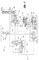
- Control system 20 represents a typical pneumatic or hydraulic control system which uses a pressurized fluid to control shifting of an auxiliary section range or splitter in a compound mechanical transmission.
- the pressurized fluid preferably air
- the pressurized fluid is delivered via a supply line 22 through a filter 24 at approximately 7,6 Bars (110 psi.).
- a filter/regulator 26 reduces the pressure to approximately 4,1 Bars (60 psi) while also providing a secondary filter to remove particulates or contaminants.
- a light lubricant or oil is introduced into the air system to lubricate the various components while also resisting corrosion.
- Regulated and filtered air is supplied to a master valve assembly, preferably located on the shift knob or shift lever.
- the vehicle operator manipulates the master valve via a switch or knob to control the splitter shift by selectively supplying or removing a pressurized fluid control signal via pilot line 30 connected to splitter valve 32.
- pilot line 30 connected to splitter valve 32.
- master valve 28 When master valve 28 is in the position illustrated in FIGURE 1, pressurized air from filter regulator 26 is blocked by master valve 28 such that splitter valve 32 is in the high-split or overdrive split position. This directs the supply air to both sides of splitter cylinder 34.
- a differential area piston 36 has a larger surface area on the rightward or direct-drive side relative to the leftward or overdrive side causing piston 36 and rod or shaft 38 to move in the direction illustrated.
- the range shift is performed based on the position of the shift lever rather than the position of a range button or knob.
- the range shift is commanded automatically based on the relative lateral position of the shift lever in selecting low-range or high-range gear ratios.
- this configuration is referred to as an autorange configuration which uses an actuating cam system, represented generally by reference numeral 42, to control a range valve 44 coupled thereto.
- pressurized air is directed from filter/regulator 26 through range valve 44 to the range cylinder cover assembly 46 which includes first and second two-way, two-position valves 48 and 50.
- Pressurized air travels from range valve 44 through pilot 52 to first valve 48 causing valve 48 to move to the right which connects the right side of range cylinder 54 and piston 56 to exhaust 58.
- Pressurized supply air travels from filter/regulator 26 through second valve 50 to fill the left side of range cylinder 54 causing range piston 56 to move toward the right or low-range position.
- cam 42 rotates causing range valve 44 to shift so that pressurized air in pilot 52 is exhausted.
- range valve 48 to shift to the left connecting pressurized air through line 58 to range cylinder 54, while second valve 50 also moves to the left connecting the left side of range cylinder 54 and piston 56 to exhaust.
- range piston 56 travels toward the left or high-range position.
- Control system 70 receives pressurized fluid, preferably air, via supply line 72.
- the supply air is filtered by filter 74 and supplied to the range cylinder cover assembly 76 which includes a filter/regulator 78 mounted to the range cylinder cover body or housing 80 such that supply air is directly ported to the range cylinder cover housing 80 to eliminate hoses connecting filter/regulator 78.
- Control system 70 replaces first and second two-position, three-way valves with a single four-way, two-position valve 82.
- the range cylinder cover assembly 76 may preferably be retrofitted to existing range cylinders.
- cam 86 rotates and operates range valve 86 via an appropriate linkage 88.
- supply air from filter/regulator 78 is blocked or dead-headed by range valve 86, and pilot 90 is exhausted.
- pilot 90 is exhausted.
- splitter shift is completed in a similar manner, although it is initiated by the operator via a shift knob or button connected to master valve 100.
- master valve 100 blocks supply air and exhausts pilot 102 such that splitter valve 104 within splitter cylinder cover assembly 106 is shifted toward the right.
- This directs the pressurized supply air to both sides of splitter cylinder 108 which includes a differential area piston 110 having a larger surface area on right side 112 relative to left side 114. This causes piston 110 to move to the left or the overdrive, high-split position.
- master valve 100 When the operator moves the splitter switch, master valve 100 is shifted downward connecting the pressurized supply air to pilot 102 causing splitter valve 104 to move to the left. This connects the right side 112 of splitter cylinder 108 and piston 110 to exhaust causing piston 110 to move to the right or direct drive, low-split position.
- Control system 120 is preferably utilized on a 13-speed transmission.
- the vehicle air supply delivers pressurized air via line 122 between filter 124 and filter/regulator 126.
- the filtered and regulated air is provided to a four-way, two-position range valve 128, a two-way, two-position splitter valve 130 and the left side 132 of splitter cylinder 134 and piston 136.
- a shift knob master valve 138 includes a master splitter valve 140 and a master range valve 142.
- Valves 140 and 142 are interlocked via an appropriate mechanism, represented generally by reference numeral 144. Valves 140 and 142 are manually operated by the vehicle operator to selectively perform a range and/or splitter shift. Interlock mechanism 144 allows a splitter shift to be performed only when valve 142 is in the high range.
- a range interlock mechanism prevents range valve 128 from being shifted when the main transmission section is in gear, i.e. a range shift may only be performed when the main transmission section is in neutral. However, the vehicle operator may preselect a range shift while the main transmission section is engaged. An appropriate interlock mechanism does not actually initiate the range shift until the operator shifts the main transmission section to neutral, as explained in greater detail below.
- the low range, overdrive split is selected.
- Supply air from filter/regulator 126 travels through splitter valve 130, located within the splitter cylinder cover 150, such that substantial equal pressure is applied to both sides of splitter piston 136.
- the differential area of the right side of piston 136 relative to the left side causes the piston to move toward the left or overdrive position.
- Supply air also travels from filter/regulator 126 to range valve 128 within range cylinder cover 152 and is directed to the left side 154 of range cylinder 156 and piston 158.
- the right side 160 of range cylinder 156 and piston 158 is exhausted through range valve 152. This causes range piston 158 to travel to the right or low-range position.
- master range valve 142 When the vehicle operator selects high range via master valve 144, master range valve 142 is shifted to the upper position which connects pilot 162 to exhaust.
- the interlock mechanism 146 allows range valve 128 to shift toward the left such that the left side 154 of range cylinder 156 of piston 158 is exhausted and pressurized fluid from filter/regulator 126 is supplied to the right side 160 of range cylinder 156 and piston 158. This causes range piston 158 to travel toward the left or high-range position.
- interlock mechanism 144 allows movement of splitter valve 140 to perform a splitter shift between the direct or low-split position and the overdrive or high-split position.
- the vehicle operator actuates the master splitter valve 140 within the shift knob master valve 138 moving it rightward to connect pilot line 164 to pilot line 166 which is exhausted through range valve 128.
- the present invention may also be used in a control system to control an 18-speed transmission.
- splitter shifts may be performed in both the low and high ranges.
- an interlock mechanism such as mechanism 144 is not required. This provides the additional five gear ratios or speeds.
- Range cylinder cover assembly 180 includes a housing or valve body 182 preferably made of anodized aluminum. Housing 182 includes four holes 184 for mounting to the range cylinder. Appropriate mounting holes 186 are provided to secure a filter/regulator (not shown) directly to a flat surface 188 of housing 182. The filter/regulator supplies pressurized fluid through supply bore 190 which is preferably counterbored to receive an O-ring. Counterbore 192 is dead-headed and supplied only for compatibility with standard filter/regulators.
- a breather 194 is used to connect the valve bore (best illustrated in FIGURE 5) to exhaust.
- a pilot cap 196 is preferably threaded into the valve bore and includes a bore to receive a standard pipe fitting for connection of the pilot air hose.
- Housing 182 includes a valve bore 200 which is oriented generally transverse to a seal plate bore 202. Although referred to as a seal plate bore 202, housing 182 serves as a positive stop for the range piston (not shown).
- a spool valve 204 is disposed within valve bore 200 and is axially translatable between the first position connecting supply bore 190 to a first side of the piston (not shown) to translate the piston in a first direction within the cylinder (not shown), and a second position connecting air from supply bore 190 to a second side of the piston.
- the spool valve 204 includes a first 206, second 208, and third 210 diameter.
- First diameter 206 is smaller than second diameter 208 and third diameter 210 to bias spool valve 204 toward the first direction (left) when equal pressure is applied to the first 206 and third 210 diameters.
- First diameter 206 has an axial bore 212 extending through the first diameter 206 and partially into the second diameter 208 and intersecting a transverse bore 214 extending through a flatted region of second diameter 208.
- a first sealing member 216 (also referred to as the slipper seal) has an annular portion extending within transverse bore 214 with a flange.
- a second sealing member 218 (also referred to as the balance seal) is positioned diametrically opposite the first sealing member 216 partially disposed within transverse bore 214 and extending radially outward to contact valve bore 200.
- a spring 220 is disposed between the sealing members 216, 218 to urge the sealing members radially outward and center the spool 204 within valve bore 200.
- An O-ring 222 is provided between the first sealing member 216 and spring 220 and also on the second sealing member 218.
- a seal plate 230 is disposed between seal plate bore 202 and valve bore 200.
- Seal plate 230 includes a first channel 232 for selectively fluidly coupling valve bore 200 to the first side of the piston (not shown) and a second channel 234, in communication with channel 238 and supply channel 236, for selectively fluidly coupling valve bore 200 to the second side of the piston (not shown).
- Bore 238 is provided for manufacturability and is sealed by a ball 240 held by a press or interference fit.
- Seal plate 230 is held within seal plate bore 202 by a snap ring 242 and includes O-rings 244, 246 such that air leakage for both positions of spool valve 204 preferably does not exceed five SCCM from 0-60 psig over the operating temperature range.
- O-ring grooves are provided on the face 246 of housing 182 to seal seal plate bore 202 and supply channel 236.
- seal plate 230 includes a first channel 232 having a threaded portion 250 for ease of disassembly.
- a dowel 252 cooperates with a corresponding slot or groove and seal plate 230 so that the first and second channels are properly aligned with the first sealing member 216. Dowel 252 prevents seal plate 230 from rotating within seal plate bore 202.
- pressurized fluid is supplied via supply bore 190 and acts on first 206 and second 208 diameters of spool 204 to provide a force which urges spool 204 rightward.
- pilot air supplied through pilot cap 196 is exhausted which allows spool 204 to travel to the right until the flange of slipper seal 216 contacts pilot cap 196.
- pilot cap 196 provides a positive stop which- limits axial travel of spool 204 in one direction.
- the second diameter 208 cooperates with valve bore 200 to provide a positive stop in the opposite direction.
- Pressurized supply air travels through bore 212 of spool 204 and through the annular slipper seal 216 into first channel 232 and seal plate bore 202. Air from the opposite side of the piston (not shown) travels through supply channel 236, second channel 234, and into region 260 which is exhausted through breather 194 (FIGURE 4).
- pressurized pilot air is provided through pilot cap 196.
- the pressurized air acts on the third diameter 210 of spool 204. Because the third diameter has a greater area relative to the first and second diameters, spool valve 204 is urged to the left by substantially equal pressure on both sides.
- pressurized supply air travels through supply bore 190, into valve bore 200, through bore 212 of spool 204, through slipper seal 216 and into second channel 234 which is connected to channels 236 and 238 to supply pressurized air to the opposite side of the piston (not shown).
- the proximate side of the piston is connected through first channel 232 to exhaust breather 194 (FIGURE 4).
- the various regions of valve bore 200 which include a supply region, an exhaust region, and a pilot region, are isolated or separated by the various sealing members which preferably include self-wiping, U-shaped cup seals 262 and 264.
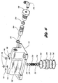
- FIGURE 6 a three-dimensional assembly drawing of the range cylinder cover assembly 180 illustrated in FIGURES 4 and 5 is shown.
- O-rings 268 are used to seal the supply bore 190 and dead-headed bore 192 between housing 182 and the direct-mounted filter/regulator (not shown).
- Splitter cylinder cover assembly 300 includes a housing 302. Pilot cap 304 is threadingly engaged with housing 302. Pilot cap 304 includes a hex head for ease in assembly and disassembly.
- a center bore 306 includes standard pipe threads to accommodate an appropriate fitting and hose to provide a pressurized fluid control signal, preferably air.
- An exhaust breather 308 is threadingly engaged to an exhaust bore.
- Housing 302 includes a valve bore, indicated generally by reference numeral 310, a seal plate bore, indicated generally by reference numeral 312, and a supply bore, indicated generally by reference numeral 314.
- valve bore 310 extends through housing 302 in a first direction while seal plate bore 312 is generally transverse to, and intersects valve bore 310.
- Supply bore 314 intersects a first portion 316 of valve bore 310.
- An exhaust bore (not specifically illustrated) intersects a second portion 318 of valve bore 310.
- a supply channel 320 extends from first portion 316 of valve bore 310 and/or supply bore 314 generally parallel to seal plate bore 312 to supply pressurized fluid to a distal side of the splitter piston (now shown).
- a spool 322 is disposed within valve bore 310 for selectively directing the pressurized supply fluid from supply bore 314 to either the supply channel 320 or the seal plate bore 312 based on whether the high-split or low-split has been commanded.
- Spool 322 includes an axial bore 324 extending from a first portion 326 having a first diameter, to a second portion 328 having a second diameter with a flatted portion 330.
- Second portion 328 of spool 322 includes a transverse bore for receiving a first sealing member (also referred to as a balance seal) 332 positioned in the transverse bore and partially extending therefrom to engage valve bore 310.
- a second sealing member (also referred to as a slipper seal) 334 is positioned diametrically opposite first sealing member 332 and extends partially within the transverse bore through spool 322.
- a spring 336 disposed within the transverse bore of spool 322 exerts a force directed radially outward relative to center of spool 322 such that first sealing member 332 and second sealing member 334 contact valve bore 310 and a third sealing member (also referred to as a seal plate) 338, respectively.
- Spring 336 assists in centering and sealing spool 322 within valve bore 310.
- a third sealing member or seal plate 338 is generally-cylindrically shaped with a flange to provide a positive stop for seal plate 338 which is positioned between valve bore 310 and seal plate bore 312. Seal plate 338 cooperates with the flange of second sealing member 334 to selectively provide pressurized supply fluid to a proximate side of the splitter piston (not shown).
- seal plate 338 includes threads for engagement with housing 302 with an appropriate seal 340, such as an O-ring.
- Pilot cap 304 is generally cylindrically shaped with a flange and positioned such that the cylindrical portion extends within valve bore 310 and cooperates with spool 322 to limit travel of spool 322 in one direction. Pilot cap 304 includes a through bore 306 for selectively supplying a pressurized fluid control signal to shift spool 322 to the high-split position. Spool 322 includes a large U-shaped (in cross-section) cup seal 342 which cooperates with the inside diameter of pilot cap 304. A small, U-shaped cup seal 344 cooperates with first portion 316 of valve bore 310 to guide spool 322 while also sealing and separating first portion 316 from second portion 318.
- regulated and filtered supply air enters housing 302 through supply bore 314 and is preferably about 60 psig.
- supply air urges spool 322 toward the left such that the through bore is aligned with the bore through seal plate 338.
- Pressurized supplied fluid is directed through seal plate 338 and supply channel 320 to provide pressurized fluid to both sides of the splitter piston (not shown). Because the splitter piston has a differential area, a substantially equal pressure on both sides will result in an unequal force such that the piston translates within the splitter cylinder in a first direction.
- pressurized pilot air preferably at 60 psig, is supplied through bore 306.
- the differential areas of spool 322 cause spool 322 to travel toward the right with substantially equal pressure on both sides. This results in supply air coming from supply bore 314 and traveling through bore 324 and spool 322 to be blocked by seal plate 338. At the same time, the bore through seal plate 338 connects the seal plate bore 312 to exhaust. As such, pressurized air is supplied to the distal side of the splitter piston through supply channel 320 while the proximate side of the splitter piston is exhausted. This allows the splitter piston to travel up into housing 302 to effect the splitter shift.
- FIGURE 9 an alternative embodiment of a splitter cylinder cover assembly according to the present invention is shown. Those components having similar structure and function as components illustrated and described with reference to FIGURE 8 are not described in detail here.
- the embodiment illustrated in FIGURE 9 includes a normally closed pilot cap 350 which extends within valve bore 352 a distance less than the normally open pilot cap 304 (FIGURE 8).
- spool assembly 356 in the absence of a pilot signal through pilot bore 354, spool assembly 356 is biased toward the left by pressurized supply air entering through supply bore 358. In this position, supply air travels through spool assembly 356 and the transverse bore, but is blocked by seal plate 360. Bore 362 through seal plate 360 couples seal plate bore 364 to exhaust.
- pilot air is supplied, spool assembly 356 translates toward the right aligning the transverse bore of the slipper seal with bore 362.
- seal plate 360 includes an orifice 366 having a size which limits the fill rate of the proximate end of the splitter piston (not shown) to control duration of the splitter shift. This may be desirable in applications having large ratio steps.
- a plug 368 disposed within the supply channel 370 includes an orifice sized to limit a fill rate of the distal end of the splitter piston to control duration of the splitter shift.
- the normally closed configuration may be utilized with or without the fill-rate limiting orifices depending upon the particular application.
- the normally open configuration illustrated in FIGURE 8 may be used with appropriate orifice sizes to limit the fill rate of the cylinder to control duration of the shift.
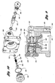
- FIGURE 10 a three-dimensional assembly drawing illustrating a splitter cylinder cover assembly according to the present invention is shown.
- FIGURE 10 is generally applicable to the assemblies illustrated in FIGURES 8 and 9 as well as the various combinations of normally open, normally closed, limited-rate, and non-orificed configurations.
Landscapes
- Engineering & Computer Science (AREA)
- General Engineering & Computer Science (AREA)
- Mechanical Engineering (AREA)
- Gear-Shifting Mechanisms (AREA)
- Fluid-Pressure Circuits (AREA)
Claims (17)
- Système de commande (70, 120) pour commander le changement de vitesse d'une section auxiliaire d'une boíte de vitesses mécanique composite, la section auxiliaire comprenant une pluralité d'engrenages avec un cylindre associé (99, 108 ; 156, 136), un piston (98, 110 ; 158, 136) et un arbre de changement de vitesse couplé à une fourchette de boíte pour engrener de manière sélective un engrenage d'une pluralité d'engrenages sur un arbre rotatif, pour modifier un rapport de vitesse d'une vitesse d'entrée de section auxiliaire à une vitesse de sortie, le système comprenant :caractérisé en ce queune culasse de cylindre (150 ; 180 ; 300) adaptée pour s'engrener avec le cylindre, la culasse de cylindre comportant un alésage de plaque de joint (202 ; 312 ; 364) et un alésage de soupape (200 ; 310 ; 352), l'alésage de soupape étant orienté généralement de manière transversale par rapport à l'alésage de plaque de joint ;une soupape à tiroir cylindrique (204) disposée à l'intérieur de l'alésage de soupape (200 ; 310 ; 352) et translatable axialement entre une première position, raccordant une alimentation de fluide sous pression à un premier côté du piston pour translater le piston dans une première direction à l'intérieur du cylindre afin d'engrener un premier engrenage de la pluralité d'engrenages et une seconde position, raccordant l'alimentation de fluide sous pression à un second côté du piston pour translater le piston dans une seconde direction à l'intérieur du cylindre afin d'engrener un second engrenage de la pluralité d'engrenages, la soupape à tiroir cylindrique ayant un premier, un deuxième et un troisième diamètres, le premier diamètre étant plus petit que le deuxième et le troisième diamètre, pour solliciter la soupape à tiroir cylindrique vers la première direction lorsqu'une pression égale est appliquée aux premier et troisième diamètres, le premier diamètre comportant un alésage axial qui s'étend à travers et intersecte un alésage transversal, qui lui-même s'étend à travers le deuxième diamètre et fait sortir la soupape à tiroir cylindrique dans une région aplatie ;un premier élément d'étanchéité (216 ; 332) comprenant une partie annulaire qui s'étend à travers l'alésage transversal du deuxième diamètre de la soupape à tiroir cylindrique, avec un rebord contactant la partie aplatie ;un deuxième élément d'étanchéité (218 ; 334) diamétralement opposé au premier élément d'étanchéité, le deuxième élément d'étanchéité étant disposé partiellement à l'intérieur de l'alésage transversal et s'étendant radialement vers l'extérieur pour contacter l'alésage de soupape ;un ressort (220 ; 336) disposé entre le premier et le deuxième éléments d'étanchéité, le ressort poussant le premier et le deuxième éléments d'étanchéité radialement vers l'extérieur pour centrer la soupape à tiroir cylindrique à l'intérieur de l'alésage de soupape ;une plaque de joint (230) disposée entre l'alésage de plaque de joint et l'alésage de soupape, la plaque de joint comprenant un premier canal pour coupler sélectivement et fluidiquement l'alésage de soupape au premier côté du piston et un second canal pour coupler sélectivement et fluidiquement l'alésage de soupape au second côté du piston ;
la plaque de joint (230) comporte une encoche pour recevoir un goujon (252) afin d'orienter la plaque de joint de manière angulaire, de sorte que les premier et second canaux soient alignés avec le premier élément d'étanchéité lorsque la soupape à tiroir cylindrique est dans la première et seconde positions, respectivement. - Système selon la revendication 1, dans lequel la plaque de joint (230) comporte une partie plate qui dépasse à l'intérieur de l'alésage de soupape et contacte le rayon du premier élément d'étanchéité.
- Système selon la revendication 1, dans lequel la plaque de joint (230) et la culasse de cylindre comportent des filets coopérant pour fixer la plaque de joint à l'intérieur de la culasse de cylindre.
- Système selon la revendication 1, dans lequel la culasse de cylindre (180) comprend une rainure et dans lequel la plaque de joint (230) est fixée à l'intérieur de la culasse du cylindre par une bague élastique (242) qui coopère avec la rainure.
- Système selon la revendication 1, comprenant, en outre :un chapeau (196 ; 304 ; 360) comportant une extrémité distale s'étendant à l'intérieur de l'alésage de soupape pour procurer une butée fixe, afin que la soupape à tiroir cylindrique définisse la première position.
- Système selon la revendication 1, comprenant, en outre :un régulateur à filtre (78 ; 126) monté sur la culasse de cylindre, le régulateur à filtre régulant la pression et filtrant le fluide sous pression, tout en délivrant le fluide sous pression filtré et régulé directement à l'alésage de soupape pour éliminer les tuyaux flexibles entre eux.
- Système selon la revendication 1, dans lequel le système commande un changement de rapport pour sélectionner soit un rapport de vitesse haute, soit un rapport de vitesse basse, pour la transmission.
- Système selon la revendication 1, dans lequel le système commande un changement de rapport de distributeur de la transmission.
- Système selon la revendication 1, dans lequel la soupape à tiroir cylindrique (204) et la culasse de cylindre (150 ; 180 ; 300) sont constituées du même matériau afin de réduire la corrosion galvanique qui peut entraíner le collage de la soupape à tiroir cylindrique à l'intérieur de l'alésage de soupape.
- Système selon la revendication 1, dans lequel la soupape à tiroir cylindrique et la culasse de cylindre sont constituées d'aluminium anodisé.
- Système selon la revendication 1, dans lequel la culasse de cylindre (150 ; 180 ; 300) comporte un orifice d'échappement qui intersecte l'alésage de soupape et dans lequel la première position de la soupape à tiroir cylindrique couple fluidiquement le second côté du piston à l'orifice d'échappement.
- Système selon la revendication 1, dans lequel la culasse de cylindre (150 ; 180 ; 300) comporte un orifice d'échappement qui intersecte l'alésage de soupape et dans lequel la seconde position de la soupape à tiroir cylindrique couple fluidiquement le premier côté du piston à l'orifice d'échappement.
- Système selon la revendication 1 pour l'utilisation dans la commande d'un changement de rapport de distributeur dans une section auxiliaire d'une transmission composite mécanique comportant un cylindre de distributeur avec un piston de distributeur raccordé à l'arbre de distributeur qui se déplace entre une position de distributeur de rapport de vitesse haute et une position de distributeur de rapport de vitesse basse, en réponse à un signal de commande de fluide sous pression, l'ensemble comportant :un chapeau de forme cylindrique (304) avec un rebord, le chapeau s'étendant à l'intérieur de l'alésage de soupape et coopérant avec le tiroir à cylindre pour limiter le déplacement du tiroir à cylindre dans une direction, le chapeau présentant un orifice pour fournir le signal de commande de fluide sous pression pour déplacer le tiroir cylindrique à la position de distributeur de rapport de vitesse haute.
- Système selon la revendication 13 comprenant, en outre :un bouchon (368) disposé à l'intérieur du canal d'alimentation pour limiter les vitesses de remplissage de l'extrémité distale du piston de distributeur pour contrôler la durée du changement de rapport de distributeur.
- Système selon la revendication 14, dans lequel le troisième élément d'étanchéité (338) comporte un orifice présentant une taille appropriée pour limiter une vitesse de remplissage de l'extrémité proximale du piston de distributeur afin de contrôler la durée du changement de rapport de distributeur.
- Système selon la revendication 1, comprenant, en outre :un bouchon (338) disposé à l'intérieur du canal d'alimentation pour limiter une vitesse de remplissage de l'extrémité distale du piston de distributeur pour contrôler la durée du changement de rapport de distributeur.
- Système selon la revendication 1 pour une utilisation dans la commande d'un changement de rapport dans une section auxiliaire d'une transmission composite mécanique comportant un cylindre de rapport, avec un piston de rapport raccordé à un arbre de rapport, qui se déplace entre une position de rapport de vitesse haute et une position de rapport de vitesse basse, en réponse à un signal de commande de fluide sous pression, l'ensemble comprenant :un régulateur de pression (126) monté sur un logement et délivrant un fluide d'alimentation filtré et régulé directement à l'alésage d'alimentation.
Applications Claiming Priority (2)
| Application Number | Priority Date | Filing Date | Title |
|---|---|---|---|
| US208122 | 1998-12-09 | ||
| US09/208,122 US6019011A (en) | 1998-12-09 | 1998-12-09 | System for control of auxiliary section of compound transmissions |
Publications (2)
| Publication Number | Publication Date |
|---|---|
| EP1010925A1 EP1010925A1 (fr) | 2000-06-21 |
| EP1010925B1 true EP1010925B1 (fr) | 2004-02-25 |
Family
ID=22773267
Family Applications (1)
| Application Number | Title | Priority Date | Filing Date |
|---|---|---|---|
| EP99124369A Expired - Lifetime EP1010925B1 (fr) | 1998-12-09 | 1999-12-07 | Système de commande à vérins pour la section auxiliare d'une boíte de vitesses composite |
Country Status (7)
| Country | Link |
|---|---|
| US (1) | US6019011A (fr) |
| EP (1) | EP1010925B1 (fr) |
| JP (1) | JP2000179682A (fr) |
| CN (1) | CN1127413C (fr) |
| BR (1) | BR9905713A (fr) |
| DE (1) | DE69915017T2 (fr) |
| ES (1) | ES2213969T3 (fr) |
Families Citing this family (7)
| Publication number | Priority date | Publication date | Assignee | Title |
|---|---|---|---|---|
| EP1610122A1 (fr) * | 2004-06-01 | 2005-12-28 | Siemens Aktiengesellschaft | Procédé et dispositif pour la détermination des défauts des aubes de turbine par un transducteur acoustique à élements en phase |
| DE102010050325A1 (de) * | 2010-11-05 | 2012-05-10 | Parker Hannifin Gmbh | Hydraulisches Steuerventil mit einem in dessen hohl ausgebildeten Steuerschieber angeordneten vier Steuerkanten aufweisenden Vorsteuerkolben |
| US8726749B2 (en) | 2011-09-25 | 2014-05-20 | Eaton Corporation | Transmission overdrive yoke position sensor for range trigger |
| US8955533B2 (en) | 2013-06-07 | 2015-02-17 | Sonnax Industries, Inc. | Multiple pressure ratio valve assembly |
| US9447871B2 (en) | 2013-11-20 | 2016-09-20 | Sonnax Industries, Inc. | Multiple-ratio boost valve |
| US10856668B2 (en) | 2017-04-10 | 2020-12-08 | Hill-Rom Services, Inc. | Mattress overlay control system with rotary valves and graphical user interface for percussion and vibration, turn assist and microclimate management |
| US12297904B2 (en) * | 2023-02-22 | 2025-05-13 | Dana Italia S.R.L. | Stand-alone, self-purging, hollow-piston hydraulic actuator |
Family Cites Families (19)
| Publication number | Priority date | Publication date | Assignee | Title |
|---|---|---|---|---|
| US3215163A (en) * | 1964-06-23 | 1965-11-02 | Republic Mfg Company | Two-position, four-way pilot operated valve |
| US4083382A (en) * | 1976-06-03 | 1978-04-11 | J. I. Case Company | Regulating valve with hydraulic detent |
| US4450869A (en) * | 1981-07-24 | 1984-05-29 | Teledyne Republic Manufacturing | Pilot-operated valve |
| BR8403161A (pt) * | 1983-07-20 | 1985-06-11 | Eaton Corp | Dispositivo de travamento para valvula |
| DE3430697A1 (de) * | 1983-12-28 | 1985-07-11 | Teledyne Industries, Inc., Los Angeles, Calif. | Ferngesteuertes ventil mit integralem filterzusammenbau |
| US4754665A (en) * | 1986-02-05 | 1988-07-05 | Eaton Corporation | Auxiliary transmission section |
| US4722237A (en) * | 1986-12-12 | 1988-02-02 | Eaton Corporation | Fluid actuated shift bar housing assembly having a centering cylinder therein |
| US5092187A (en) * | 1990-11-08 | 1992-03-03 | Rockwell International Corporation | Auxiliary transmission shift control system |
| US5144863A (en) * | 1991-08-01 | 1992-09-08 | Eaton Corporation | Compound change gear transmission |
| US5207113A (en) * | 1991-09-30 | 1993-05-04 | Rockwell International Corporation | Sleeve for aligning two discrete structures having adjoining bores |
| US5224392A (en) * | 1992-01-23 | 1993-07-06 | Eaton Corporation | Variable pressure range section actuator piston |
| US5186066A (en) * | 1992-01-23 | 1993-02-16 | Eaton Corporation | Dual pressure pressure regulator |
| US5216931A (en) * | 1992-01-23 | 1993-06-08 | Eaton Corporation | Interlock mechanism for range section slave valve |
| US5193410A (en) * | 1992-01-23 | 1993-03-16 | Eaton Corporation | Range section protection valve assembly |
| US5199312A (en) * | 1992-01-23 | 1993-04-06 | Eaton Corporation | Range section actuator control system and method for preventing damage to range section synchronizers |
| US5199311A (en) * | 1992-01-23 | 1993-04-06 | Eaton Corporation | Variable pressure range section actuator assembly |
| US5222404A (en) * | 1992-01-23 | 1993-06-29 | Eaton Corporation | Auxiliary section actuator control system and method |
| US5231895A (en) * | 1992-01-23 | 1993-08-03 | Eaton Corporation | Auxiliary section actuator air control system |
| US5218878A (en) * | 1992-01-23 | 1993-06-15 | Eaton Corporation | Two-stage range piston-cylinder assembly |
-
1998
- 1998-12-09 US US09/208,122 patent/US6019011A/en not_active Expired - Fee Related
-
1999
- 1999-12-07 DE DE69915017T patent/DE69915017T2/de not_active Expired - Fee Related
- 1999-12-07 EP EP99124369A patent/EP1010925B1/fr not_active Expired - Lifetime
- 1999-12-07 ES ES99124369T patent/ES2213969T3/es not_active Expired - Lifetime
- 1999-12-08 BR BR9905713-1A patent/BR9905713A/pt not_active IP Right Cessation
- 1999-12-09 JP JP11350329A patent/JP2000179682A/ja active Pending
- 1999-12-09 CN CN99124770A patent/CN1127413C/zh not_active Expired - Fee Related
Also Published As
| Publication number | Publication date |
|---|---|
| EP1010925A1 (fr) | 2000-06-21 |
| DE69915017T2 (de) | 2004-10-21 |
| CN1127413C (zh) | 2003-11-12 |
| ES2213969T3 (es) | 2004-09-01 |
| CN1257019A (zh) | 2000-06-21 |
| JP2000179682A (ja) | 2000-06-27 |
| DE69915017D1 (de) | 2004-04-01 |
| BR9905713A (pt) | 2000-09-05 |
| US6019011A (en) | 2000-02-01 |
Similar Documents
| Publication | Publication Date | Title |
|---|---|---|
| US5038627A (en) | Vehicle transmission with manually shifted lower gears and automatically shifted upper gears | |
| US5676026A (en) | Hydraulic pressure control system | |
| US5450767A (en) | Vehicle transmission having manually shifted lower gears and automatically shifted higher gears | |
| CN101061335B (zh) | 一种用于多档变速器主箱的换档禁止装置及方法 | |
| US7861612B2 (en) | Transmission range shift control with neutral position lock | |
| AU671070B1 (en) | Dual pressurized fluid actuated shifting mechanism | |
| KR100246971B1 (ko) | 3위치 시프트 액츄에이터 | |
| CA1220648A (fr) | Systeme de verrouilllage reciproque sur rampe de changement de vitesses | |
| EP0694713B1 (fr) | Dispositif de commande pour transmission à commande hydraulique | |
| EP0713987B1 (fr) | Système de commande hydraulique pour transmission automatique à embrayages multiples | |
| KR920000036B1 (ko) | 보조변속기 기어변경 조정장치 | |
| EP1010925B1 (fr) | Système de commande à vérins pour la section auxiliare d'une boíte de vitesses composite | |
| CA2053682C (fr) | Systeme auxiliaire de selecteur de boite de vitesse | |
| JP3531117B2 (ja) | 機械式変速機用の流体作動式シフトアクチュエータ | |
| US4516669A (en) | Gear shifting device | |
| EP0802356B1 (fr) | Dispositif électrohydraulique pour commander les servo-actionneurs d'une boíte de vitesses | |
| KR0175156B1 (ko) | 작업차의 주행변속시스템 | |
| GB2057607A (en) | Arrangement for Blocking a Vehicle Clutch | |
| USRE34260E (en) | Dual pressure pressurized fluid actuated shifting mechanism | |
| US5279172A (en) | Four position fluid-actuated piston arrangement | |
| US4567791A (en) | Manual device for detecting malfunction of a solenoid valve | |
| US7069806B2 (en) | Transmission auxiliary box seal system | |
| EP0622571B1 (fr) | Système de commande hydraulique pour une transmission | |
| JP2897059B2 (ja) | 自動変速機のシフト制御装置 |
Legal Events
| Date | Code | Title | Description |
|---|---|---|---|
| PUAI | Public reference made under article 153(3) epc to a published international application that has entered the european phase |
Free format text: ORIGINAL CODE: 0009012 |
|
| 17P | Request for examination filed |
Effective date: 20000407 |
|
| AK | Designated contracting states |
Kind code of ref document: A1 Designated state(s): DE ES FR GB IT SE |
|
| AX | Request for extension of the european patent |
Free format text: AL;LT;LV;MK;RO;SI |
|
| AKX | Designation fees paid |
Free format text: DE ES FR GB IT SE |
|
| 17Q | First examination report despatched |
Effective date: 20020925 |
|
| GRAP | Despatch of communication of intention to grant a patent |
Free format text: ORIGINAL CODE: EPIDOSNIGR1 |
|
| GRAS | Grant fee paid |
Free format text: ORIGINAL CODE: EPIDOSNIGR3 |
|
| GRAA | (expected) grant |
Free format text: ORIGINAL CODE: 0009210 |
|
| AK | Designated contracting states |
Kind code of ref document: B1 Designated state(s): DE ES FR GB IT SE |
|
| REG | Reference to a national code |
Ref country code: GB Ref legal event code: FG4D |
|
| REF | Corresponds to: |
Ref document number: 69915017 Country of ref document: DE Date of ref document: 20040401 Kind code of ref document: P |
|
| REG | Reference to a national code |
Ref country code: SE Ref legal event code: TRGR |
|
| REG | Reference to a national code |
Ref country code: ES Ref legal event code: FG2A Ref document number: 2213969 Country of ref document: ES Kind code of ref document: T3 |
|
| ET | Fr: translation filed | ||
| PLBE | No opposition filed within time limit |
Free format text: ORIGINAL CODE: 0009261 |
|
| STAA | Information on the status of an ep patent application or granted ep patent |
Free format text: STATUS: NO OPPOSITION FILED WITHIN TIME LIMIT |
|
| 26N | No opposition filed |
Effective date: 20041126 |
|
| PGFP | Annual fee paid to national office [announced via postgrant information from national office to epo] |
Ref country code: GB Payment date: 20051104 Year of fee payment: 7 |
|
| PGFP | Annual fee paid to national office [announced via postgrant information from national office to epo] |
Ref country code: FR Payment date: 20051201 Year of fee payment: 7 |
|
| PGFP | Annual fee paid to national office [announced via postgrant information from national office to epo] |
Ref country code: SE Payment date: 20051202 Year of fee payment: 7 |
|
| PGFP | Annual fee paid to national office [announced via postgrant information from national office to epo] |
Ref country code: ES Payment date: 20051216 Year of fee payment: 7 |
|
| PGFP | Annual fee paid to national office [announced via postgrant information from national office to epo] |
Ref country code: DE Payment date: 20051230 Year of fee payment: 7 |
|
| PG25 | Lapsed in a contracting state [announced via postgrant information from national office to epo] |
Ref country code: SE Free format text: LAPSE BECAUSE OF NON-PAYMENT OF DUE FEES Effective date: 20061208 |
|
| PGFP | Annual fee paid to national office [announced via postgrant information from national office to epo] |
Ref country code: IT Payment date: 20061231 Year of fee payment: 8 |
|
| PG25 | Lapsed in a contracting state [announced via postgrant information from national office to epo] |
Ref country code: DE Free format text: LAPSE BECAUSE OF NON-PAYMENT OF DUE FEES Effective date: 20070703 |
|
| EUG | Se: european patent has lapsed | ||
| GBPC | Gb: european patent ceased through non-payment of renewal fee |
Effective date: 20061207 |
|
| REG | Reference to a national code |
Ref country code: FR Ref legal event code: ST Effective date: 20070831 |
|
| PG25 | Lapsed in a contracting state [announced via postgrant information from national office to epo] |
Ref country code: GB Free format text: LAPSE BECAUSE OF NON-PAYMENT OF DUE FEES Effective date: 20061207 |
|
| REG | Reference to a national code |
Ref country code: ES Ref legal event code: FD2A Effective date: 20061209 |
|
| PG25 | Lapsed in a contracting state [announced via postgrant information from national office to epo] |
Ref country code: FR Free format text: LAPSE BECAUSE OF NON-PAYMENT OF DUE FEES Effective date: 20070102 Ref country code: ES Free format text: LAPSE BECAUSE OF NON-PAYMENT OF DUE FEES Effective date: 20061209 |
|
| PG25 | Lapsed in a contracting state [announced via postgrant information from national office to epo] |
Ref country code: IT Free format text: LAPSE BECAUSE OF NON-PAYMENT OF DUE FEES Effective date: 20071207 |