EP1010927A2 - Schlauchquetschventil und Haltevorrichtung - Google Patents
Schlauchquetschventil und Haltevorrichtung Download PDFInfo
- Publication number
- EP1010927A2 EP1010927A2 EP99650117A EP99650117A EP1010927A2 EP 1010927 A2 EP1010927 A2 EP 1010927A2 EP 99650117 A EP99650117 A EP 99650117A EP 99650117 A EP99650117 A EP 99650117A EP 1010927 A2 EP1010927 A2 EP 1010927A2
- Authority
- EP
- European Patent Office
- Prior art keywords
- valve body
- valve
- bracket
- assembly
- base
- Prior art date
- Legal status (The legal status is an assumption and is not a legal conclusion. Google has not performed a legal analysis and makes no representation as to the accuracy of the status listed.)
- Withdrawn
Links
- 230000014759 maintenance of location Effects 0.000 claims abstract description 7
- 238000003780 insertion Methods 0.000 claims description 2
- 230000037431 insertion Effects 0.000 claims description 2
- 238000012986 modification Methods 0.000 description 3
- 230000004048 modification Effects 0.000 description 3
- 239000012530 fluid Substances 0.000 description 2
- 239000000463 material Substances 0.000 description 2
- 238000000034 method Methods 0.000 description 2
- 239000004677 Nylon Substances 0.000 description 1
- 230000000712 assembly Effects 0.000 description 1
- 238000000429 assembly Methods 0.000 description 1
- 229920001778 nylon Polymers 0.000 description 1
- 238000005192 partition Methods 0.000 description 1
- 229920006324 polyoxymethylene Polymers 0.000 description 1
Images

Classifications
-
- F—MECHANICAL ENGINEERING; LIGHTING; HEATING; WEAPONS; BLASTING
- F16—ENGINEERING ELEMENTS AND UNITS; GENERAL MEASURES FOR PRODUCING AND MAINTAINING EFFECTIVE FUNCTIONING OF MACHINES OR INSTALLATIONS; THERMAL INSULATION IN GENERAL
- F16K—VALVES; TAPS; COCKS; ACTUATING-FLOATS; DEVICES FOR VENTING OR AERATING
- F16K7/00—Diaphragm valves or cut-off apparatus, e.g. with a member deformed, but not moved bodily, to close the passage ; Pinch valves
- F16K7/02—Diaphragm valves or cut-off apparatus, e.g. with a member deformed, but not moved bodily, to close the passage ; Pinch valves with tubular diaphragm
- F16K7/04—Diaphragm valves or cut-off apparatus, e.g. with a member deformed, but not moved bodily, to close the passage ; Pinch valves with tubular diaphragm constrictable by external radial force
- F16K7/06—Diaphragm valves or cut-off apparatus, e.g. with a member deformed, but not moved bodily, to close the passage ; Pinch valves with tubular diaphragm constrictable by external radial force by means of a screw-spindle, cam, or other mechanical means
- F16K7/061—Screw clamps
-
- Y—GENERAL TAGGING OF NEW TECHNOLOGICAL DEVELOPMENTS; GENERAL TAGGING OF CROSS-SECTIONAL TECHNOLOGIES SPANNING OVER SEVERAL SECTIONS OF THE IPC; TECHNICAL SUBJECTS COVERED BY FORMER USPC CROSS-REFERENCE ART COLLECTIONS [XRACs] AND DIGESTS
- Y10—TECHNICAL SUBJECTS COVERED BY FORMER USPC
- Y10T—TECHNICAL SUBJECTS COVERED BY FORMER US CLASSIFICATION
- Y10T137/00—Fluid handling
- Y10T137/6851—With casing, support, protector or static constructional installations
- Y10T137/6966—Static constructional installations
- Y10T137/6969—Buildings
- Y10T137/698—Wall
Definitions
- the present invention relates generally to an appliance mounting device and, more particularly, to a tubing pinch valve and mounting bracket assembly.
- an assembly as specified in the claims is also directed to a method by which the described apparatus operates and including method steps for carrying out every function of the apparatus.
- the present invention is directed to a tubing pinch valve and mounting bracket assembly that meets the aforementioned needs.
- the assembly is very simple and inexpensive, yet it provides effective mounting of the pinch valve and versatility in the orientation of the valve and tubing relative to the panel or other support surface to which the assembly is mounted.
- the tubing pinch valve itself has a cylindrical valve body with a tube receiving bore.
- the mounting bracket has a flexible base adapted for mounting onto any suitable support and a pair of jaws having a size and configuration for engagement with the valve body.
- the valve body and each of the jaws are provided with complimentary retention members that engage to prevent axial or rotational movement of the valve.
- Another object of the invention is to provide versatility in the orientation of the valve and tubing relative to a mounting panel, thereby allowing the tubing to be positioned either in the front or rear of the mounting panel.
- Another object of the invention is to provide a convenient mounting assembly for a tubing pinch valve so that the valve may be operated using only one hand.
- Still another object of the present invention is to permit mounting of the pinch valve without the need for extensive redesign of the valve itself.
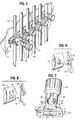
- the present invention pertains to a tubing pinch valve and mounting bracket assembly designated generally as 10.
- the assembly includes both a tubing pinch valve 12 and a mounting bracket 14 designed to cooperate for mounting to any suitable support, such as panel 16.
- any suitable support such as panel 16.
- the preferred valve is that described in United States Patent No. 5,197,708, the disclosure of which is incorporated herein by reference.
- valve 12 includes a cylindrical valve body 18 having a bore or through hole 20 for receipt of the tubing and an internally threaded slot 22.
- Valve body 18 also includes diametrically opposed, generally tangential recesses 24, each of the recesses having a radially protruding key 26.
- the key 26 is preferably formed as an axially extending partition across the width of recess 24. As illustrated, the recesses 24 may be positioned adjacent the end 25 of valve body 18, though that position may be changed to accommodate specific applications.
- the valve 12 also includes an integral knob and stem, 30 and 32 respectively. More particularly, the knob and stem are positioned concentrically, thereby forming an annular space 33.
- the valve stem 32 is provided with external threads that engage the internal threads on slot 22. As a result, by rotation of knob 30, the stem 32 is moved axially to adjust the cross-sectional flow area within flexible tubing 38 as illustrated in FIGURE 3. Further details of the structure and operation of the valve, itself, may be found in U.S. Patent No. 5,197,708.
- the embodiment illustrated includes a mounting bracket 14 comprised of a base 40 and a pair of upstanding jaws 42.
- the base 40 includes end panels 44 and 46 joined by flexible side rails 48 and 49, thereby defining a central aperture 50. End panels 44, 46 are provided with suitable mounting holes 52 and 54 to accommodate threaded fasteners 56 and 58 for firmly mounting the bracket to panel 16.
- Each of the jaws 42 includes an inner wall 60 and supporting strut walls 62, thereby rigidly joining the jaws to base 40.
- the jaws terminate with a pair of inwardly facing flanges 64, each having a keyway 66.
- the flanges 64 and keyways 66 are configured to engage the recesses 24 and keys 26 on valve body 12 when the jaws are parallel to one another. However, by flexing the base 40, as illustrated in FIGURES 2 and 7, the jaws are separated allowing disengagement of the flanges 64 and recesses 24. Of course, when the base 40 is locked down against its support surface, as illustrated in FIGURE 3, the jaws remain in parallel alignment and the flanges remain in fixed engagement with the valve body recesses. Thus, the valve 12 position is fixed relative to the panel 16.
- the jaws 42 need not employ the specific retention members illustrated in FIGURE 4.
- alternative retention members shown in FIGURES 8 and 9, may be found suitable.
- the valve body 18 is provided with a tangential recess 70, and the inner wall 60 of jaw 42 includes a complimentary flange 72.
- the valve body 18 is provided with a radially extending protuberance 76 and inner wall 60 of jaw 42 has a complimentary aperture.
- the retention member is capable of resisting both axial (pull out) and rotational (turning) forces typically applied to the valve in normal operation.
- the tubing 38 is disposed on one side of panel 16, whereas the valve actuation knob 30 is located on the opposite side of the panel.
- base aperture 50 must necessarily be sized to permit insertion of valve body 18.
- FIGURES 6 and 7 illustrate another arrangement, namely the base-mount arrangement, in which the valve 12, mounting bracket 14 and tubing 38 are all located on the same side of the support surface or panel 16.
- the present invention permits the same mounting bracket 14 to be used for both panel-mount and base-mount arrangements.
- the flanges 64 are located on the free end of inner walls 60 and spaced from base 40 a sufficient distance so that neither panel 16 nor base 40 interferes with tubing 38 disposed within bore 20.
- the mounting bracket 14 may be constructed from many different materials well known to those of skill in the art. Particularly preferred materials are nylon or acetal polymers.
Landscapes
- Engineering & Computer Science (AREA)
- General Engineering & Computer Science (AREA)
- Mechanical Engineering (AREA)
- Valve Housings (AREA)
- Supports For Pipes And Cables (AREA)
Applications Claiming Priority (2)
| Application Number | Priority Date | Filing Date | Title |
|---|---|---|---|
| US215609 | 1998-12-17 | ||
| US09/215,609 US6082702A (en) | 1998-12-17 | 1998-12-17 | Tubing pinch valve and mounting bracket assembly |
Publications (2)
| Publication Number | Publication Date |
|---|---|
| EP1010927A2 true EP1010927A2 (de) | 2000-06-21 |
| EP1010927A3 EP1010927A3 (de) | 2001-09-12 |
Family
ID=22803677
Family Applications (1)
| Application Number | Title | Priority Date | Filing Date |
|---|---|---|---|
| EP99650117A Withdrawn EP1010927A3 (de) | 1998-12-17 | 1999-12-16 | Schlauchquetschventil und Haltevorrichtung |
Country Status (5)
| Country | Link |
|---|---|
| US (1) | US6082702A (de) |
| EP (1) | EP1010927A3 (de) |
| JP (1) | JP2000179728A (de) |
| AU (1) | AU765113B2 (de) |
| ZA (1) | ZA996725B (de) |
Cited By (1)
| Publication number | Priority date | Publication date | Assignee | Title |
|---|---|---|---|---|
| US7798650B2 (en) | 2003-01-21 | 2010-09-21 | Miller Richard J | Image projection device and method |
Families Citing this family (10)
| Publication number | Priority date | Publication date | Assignee | Title |
|---|---|---|---|---|
| US7569028B2 (en) * | 2001-10-12 | 2009-08-04 | Flexcorp | Fluid flow adjustment mechanism |
| US7066441B2 (en) * | 2003-03-14 | 2006-06-27 | Saint-Gobain Performance Plastics Corporation | Flow restrictor |
| US7350537B2 (en) * | 2004-11-29 | 2008-04-01 | Cnh America Llc | Valve mounting bracket |
| CA2673099A1 (en) * | 2006-12-11 | 2008-06-19 | Ge Healthcare Bio-Sciences Ab | Pinch valve |
| US20140264125A1 (en) * | 2013-03-15 | 2014-09-18 | Del Fularon | Thermoplastic or elastomeric single use high purity full flow pinch valve for biotech applications |
| US9803754B2 (en) * | 2014-12-04 | 2017-10-31 | Resolution Air Ltd. | Pinch valve systems and methods |
| FR3053051B1 (fr) * | 2016-06-24 | 2022-11-11 | Cellprothera | Cassette et automate de culture cellulaire |
| CN106015746B (zh) * | 2016-07-18 | 2019-01-08 | 李敏峰 | 管道接头固定板及固定结构 |
| US11131398B2 (en) | 2018-08-14 | 2021-09-28 | Automatic Switch Company | Smart pinch valve |
| US11221078B2 (en) | 2018-08-14 | 2022-01-11 | Automatic Switch Company | Pinch valve guard |
Citations (1)
| Publication number | Priority date | Publication date | Assignee | Title |
|---|---|---|---|---|
| US5197708A (en) | 1992-08-11 | 1993-03-30 | Flow-Rite Controls, Ltd. | Tubing pinch valve device |
Family Cites Families (5)
| Publication number | Priority date | Publication date | Assignee | Title |
|---|---|---|---|---|
| FR1268397A (fr) * | 1960-09-29 | 1961-07-28 | Nuquip Ltd | Dispositif se montant sur un tuyau compressible en vue de son obturation temporaire |
| US4394097A (en) * | 1981-04-13 | 1983-07-19 | Honeywell, Inc. | Retaining apparatus |
| FR2542558A1 (fr) * | 1983-03-11 | 1984-09-14 | Thomson Brandt | Dispositif de fixation d'un objet, notamment un transformateur, a un fond |
| DE3928616A1 (de) * | 1989-08-30 | 1991-03-07 | Phoenix Ag | Huelse als grundkoerper eines rueckschlagventiles bzw. eines durchlassbegrenzers sowie als integriertes teil eines kfz-kruemmerschlauches, insbesondere einer kfz-formschlauchverzweigung |
| US5031658A (en) * | 1990-08-21 | 1991-07-16 | Moen Incorporated | Plaster ground with fastener-free mounting |
-
1998
- 1998-12-17 US US09/215,609 patent/US6082702A/en not_active Expired - Lifetime
-
1999
- 1999-10-26 ZA ZA9906725A patent/ZA996725B/xx unknown
- 1999-12-16 EP EP99650117A patent/EP1010927A3/de not_active Withdrawn
- 1999-12-16 JP JP11357071A patent/JP2000179728A/ja not_active Withdrawn
- 1999-12-16 AU AU65304/99A patent/AU765113B2/en not_active Ceased
Patent Citations (1)
| Publication number | Priority date | Publication date | Assignee | Title |
|---|---|---|---|---|
| US5197708A (en) | 1992-08-11 | 1993-03-30 | Flow-Rite Controls, Ltd. | Tubing pinch valve device |
Cited By (1)
| Publication number | Priority date | Publication date | Assignee | Title |
|---|---|---|---|---|
| US7798650B2 (en) | 2003-01-21 | 2010-09-21 | Miller Richard J | Image projection device and method |
Also Published As
| Publication number | Publication date |
|---|---|
| US6082702A (en) | 2000-07-04 |
| JP2000179728A (ja) | 2000-06-27 |
| AU6530499A (en) | 2000-06-22 |
| ZA996725B (en) | 2000-05-15 |
| EP1010927A3 (de) | 2001-09-12 |
| AU765113B2 (en) | 2003-09-11 |
Similar Documents
| Publication | Publication Date | Title |
|---|---|---|
| EP1010927A2 (de) | Schlauchquetschventil und Haltevorrichtung | |
| US7240716B2 (en) | System for coupling roller shade tubes | |
| US6868590B2 (en) | Quick-turn panel fastener | |
| US4872710A (en) | Releasable quick connect fitting | |
| US20030070223A1 (en) | Combined faucet and drain assembly | |
| US4480163A (en) | Vandal-resistant push button electrical switch assembly | |
| CA2602045A1 (en) | Recessed light fixture | |
| US5307596A (en) | Wall assembly support apparatus | |
| JPH03221383A (ja) | 螺旋状コイル挿入体の取付け工具 | |
| US3661356A (en) | Inlet valve assembly for pneumatic system | |
| US5560678A (en) | Device for joining together chairs in a row | |
| US5378124A (en) | Method and means for assembling a pump and motor | |
| US4949625A (en) | Air volume damper kit and assembly | |
| EP0117549B1 (de) | Auf einer Mauer montierbarer Rohrbelüfter | |
| US6030003A (en) | Gas supply device | |
| EP0566213A2 (de) | Schwenkbare Armlehne für Kraftfahrzeuge | |
| AU676935B2 (en) | A drive gear for a roller door operator | |
| US20190092419A1 (en) | System and method for detachable handlebars with tapered insert structure | |
| US12601367B2 (en) | Connecting member and arrangement | |
| JP2992494B2 (ja) | 吸排弁 | |
| JPH10274217A (ja) | 環状部材の固定構造 | |
| KR0120455Y1 (ko) | 자전거 프레임의 절첩장치 | |
| GB2209555A (en) | Externally accessible clutching adjustable latching mechanism | |
| US5803681A (en) | Handle retainer for milling machines | |
| NZ314437A (en) | Drive for roller door with recess in drive housing for locating over door axle |
Legal Events
| Date | Code | Title | Description |
|---|---|---|---|
| PUAI | Public reference made under article 153(3) epc to a published international application that has entered the european phase |
Free format text: ORIGINAL CODE: 0009012 |
|
| AK | Designated contracting states |
Kind code of ref document: A2 Designated state(s): AT BE CH CY DE DK ES FI FR GB GR IE IT LI LU MC NL PT SE |
|
| AX | Request for extension of the european patent |
Free format text: AL;LT;LV;MK;RO;SI |
|
| PUAL | Search report despatched |
Free format text: ORIGINAL CODE: 0009013 |
|
| AK | Designated contracting states |
Kind code of ref document: A3 Designated state(s): AT BE CH CY DE DK ES FI FR GB GR IE IT LI LU MC NL PT SE |
|
| AX | Request for extension of the european patent |
Free format text: AL;LT;LV;MK;RO;SI |
|
| RIC1 | Information provided on ipc code assigned before grant |
Free format text: 7F 16K 7/06 A, 7F 16B 9/02 B |
|
| 17P | Request for examination filed |
Effective date: 20020312 |
|
| AKX | Designation fees paid |
Free format text: AT BE CH CY DE DK ES FI FR GB GR IE IT LI LU MC NL PT SE |
|
| 17Q | First examination report despatched |
Effective date: 20031113 |
|
| GRAP | Despatch of communication of intention to grant a patent |
Free format text: ORIGINAL CODE: EPIDOSNIGR1 |
|
| STAA | Information on the status of an ep patent application or granted ep patent |
Free format text: STATUS: THE APPLICATION IS DEEMED TO BE WITHDRAWN |
|
| 18D | Application deemed to be withdrawn |
Effective date: 20050209 |