EP1010931A1 - Lösbare Verbindung von rotationssymmetrischen Bauteilen - Google Patents
Lösbare Verbindung von rotationssymmetrischen Bauteilen Download PDFInfo
- Publication number
- EP1010931A1 EP1010931A1 EP99124682A EP99124682A EP1010931A1 EP 1010931 A1 EP1010931 A1 EP 1010931A1 EP 99124682 A EP99124682 A EP 99124682A EP 99124682 A EP99124682 A EP 99124682A EP 1010931 A1 EP1010931 A1 EP 1010931A1
- Authority
- EP
- European Patent Office
- Prior art keywords
- sleeve
- component
- connection arrangement
- arrangement according
- ring
- Prior art date
- Legal status (The legal status is an assumption and is not a legal conclusion. Google has not performed a legal analysis and makes no representation as to the accuracy of the status listed.)
- Granted
Links
- 239000000463 material Substances 0.000 claims description 4
- 238000000034 method Methods 0.000 claims description 4
- 230000009471 action Effects 0.000 claims description 3
- 230000008569 process Effects 0.000 claims description 2
- 230000003068 static effect Effects 0.000 claims description 2
- 230000002093 peripheral effect Effects 0.000 abstract 1
- 238000004519 manufacturing process Methods 0.000 description 19
- 238000010276 construction Methods 0.000 description 4
- 230000009467 reduction Effects 0.000 description 4
- 150000001875 compounds Chemical class 0.000 description 2
- 238000005516 engineering process Methods 0.000 description 2
- 238000003801 milling Methods 0.000 description 2
- 229910000831 Steel Inorganic materials 0.000 description 1
- 238000010521 absorption reaction Methods 0.000 description 1
- 238000005520 cutting process Methods 0.000 description 1
- 230000007423 decrease Effects 0.000 description 1
- 230000006866 deterioration Effects 0.000 description 1
- 238000005553 drilling Methods 0.000 description 1
- 238000005242 forging Methods 0.000 description 1
- 238000000227 grinding Methods 0.000 description 1
- 230000006872 improvement Effects 0.000 description 1
- 238000009434 installation Methods 0.000 description 1
- 230000003993 interaction Effects 0.000 description 1
- 238000003754 machining Methods 0.000 description 1
- 238000005457 optimization Methods 0.000 description 1
- 239000010959 steel Substances 0.000 description 1
- 238000003860 storage Methods 0.000 description 1
- 238000007514 turning Methods 0.000 description 1
Images



Classifications
-
- F—MECHANICAL ENGINEERING; LIGHTING; HEATING; WEAPONS; BLASTING
- F16—ENGINEERING ELEMENTS AND UNITS; GENERAL MEASURES FOR PRODUCING AND MAINTAINING EFFECTIVE FUNCTIONING OF MACHINES OR INSTALLATIONS; THERMAL INSULATION IN GENERAL
- F16L—PIPES; JOINTS OR FITTINGS FOR PIPES; SUPPORTS FOR PIPES, CABLES OR PROTECTIVE TUBING; MEANS FOR THERMAL INSULATION IN GENERAL
- F16L23/00—Flanged joints
- F16L23/02—Flanged joints the flanges being connected by members tensioned axially
- F16L23/024—Flanged joints the flanges being connected by members tensioned axially characterised by how the flanges are joined to, or form an extension of, the pipes
- F16L23/028—Flanged joints the flanges being connected by members tensioned axially characterised by how the flanges are joined to, or form an extension of, the pipes the flanges being held against a shoulder
-
- F—MECHANICAL ENGINEERING; LIGHTING; HEATING; WEAPONS; BLASTING
- F16—ENGINEERING ELEMENTS AND UNITS; GENERAL MEASURES FOR PRODUCING AND MAINTAINING EFFECTIVE FUNCTIONING OF MACHINES OR INSTALLATIONS; THERMAL INSULATION IN GENERAL
- F16L—PIPES; JOINTS OR FITTINGS FOR PIPES; SUPPORTS FOR PIPES, CABLES OR PROTECTIVE TUBING; MEANS FOR THERMAL INSULATION IN GENERAL
- F16L23/00—Flanged joints
- F16L23/02—Flanged joints the flanges being connected by members tensioned axially
- F16L23/036—Flanged joints the flanges being connected by members tensioned axially characterised by the tensioning members, e.g. specially adapted bolts or C-clamps
-
- F—MECHANICAL ENGINEERING; LIGHTING; HEATING; WEAPONS; BLASTING
- F16—ENGINEERING ELEMENTS AND UNITS; GENERAL MEASURES FOR PRODUCING AND MAINTAINING EFFECTIVE FUNCTIONING OF MACHINES OR INSTALLATIONS; THERMAL INSULATION IN GENERAL
- F16L—PIPES; JOINTS OR FITTINGS FOR PIPES; SUPPORTS FOR PIPES, CABLES OR PROTECTIVE TUBING; MEANS FOR THERMAL INSULATION IN GENERAL
- F16L55/00—Devices or appurtenances for use in, or in connection with, pipes or pipe systems
- F16L55/10—Means for stopping flow in pipes or hoses
- F16L55/115—Caps
Definitions
- the invention relates to a releasable connection arrangement for force and positive connection of rotationally symmetrical, paired or unpaired components, for example for extremely stressed connections large diameter of pipe or cylinder ends with each other, also for connections of machine / valve housings or Pipe / cylinder ends with a curved, flat or the intended use correspondingly designed closure cover, for Lid locks on high pressure hydraulic cylinders and for connections of rotating components, e.g. Slewing bearings with their connecting structures according to the preamble of claims 1, 2 and 3.
- EP 0 775 863 B1 describes a detachable connection arrangement for non-positive and positive connection of rotationally symmetrical components known that compared to conventional compounds with smaller dimensions a significant improvement in terms of Resilience achieved and with flange connections the security against Leaks increased. At the same time, the vulnerability to Deterioration of the tension state reduced. In contrast to the conventional standard flanges, which are overhanging due to the geometry this connection represents a compact design and leads to Material savings. In almost all areas of technology arise in addition to economic advantages, especially in chemistry and in Production, transportation and processing of oil and gas immense ecological advantages. With connection arrangements with relatively large diameters lead to high manufacturing problems Processing and manufacturing costs.
- Components with projecting extensions or attached sockets may not always open Large boring machines are processed so that the use of portable Boring mills is required. In terms of performance, these are with large boring mills not comparable. Because the holes in the sleeve for receiving the clamping screws are not at a right angle to the horizontal or are arranged to the vertical axis direction of the boring mills Long spindles required. Because of vibrations the drilling capacity of the spindles is limited. It turns out long Processing times that lead to high processing costs.
- the object of the invention is to provide a connection arrangement of the specified Kind, especially for large and extremely loaded components to avoid to design individual or all of the disadvantages described above, that they are especially compared to the known arrangement EP 0 775 863 B1 is cheaper to produce, the entire Production costs in economic relation to those with the EP 0 775 863 B1.
- each of the recesses has a contact surface on, which are in the circumferential direction perpendicular to the central or bracing axes the clamping elements extends symmetrically on both sides.
- the clamping elements must be in place to achieve the positive and positive locking of this surface lie over the entire surface and have a high surface quality.
- the size of the Angle between the wedge surfaces of the clamping elements or the contact surfaces the sleeve and the respective bracing or center axes of the Clamping elements set. This is to be chosen so that after the Bracing a static friction and thus a self-locking of the clamped components or the connection arrangement is present. The then forces required to maintain the condition are low.
- the design of the sleeve according to the invention results additional advantages. Based on the size of the transferable loads and the dimensioning of the components gives the possibility that Number of recesses in the circumferential direction to the minimum number of to reduce required clamping elements.
- the aim should be that To arrange recesses in the sleeve at a distance from one another, so that a radial web remains between two of the recesses. While in an embodiment according to EP 0 775 863 B1 a volume for receiving the clamping elements through cutting work must be worked out of the sleeve over its full circumference, this now decreases according to the number of required Clamping elements.
- the slip and load behavior of the sleeve by the full remaining in the main loaded area Cross section increased so that the wall thickness while maintaining the required state of tension by means of an optimization can be reduced. This leads to further cost reductions.
- connection arrangement there is the possibility of using these to achieve the advantages to be achieved according to EP 0 775 863 B1 also to be used on the compounds which due to the necessity of a procedure at short intervals have to be opened and tightened again.
- Tensioning means relatively fast acting devices or units to be ordered. These can be mechanical lever or Eccentric tensions as well as hydraulic, pneumatic, electrical or correspondingly thermally acting aggregates, each of which individually or in combination with each other the required clamping force can generate. These are combined by industry as integrated Components, e.g. as an electric motor and oil hydraulic pump in a housing or as a pneumatic hydraulic feed unit offered. This tensioning means can be independent of the operating load to get voted.
- the position or the axis of action of the tensioning means, both with the tensioning elements and with the braced Component releasably or permanently connected as required to be arranged does not need the position of the bracing axis of the To have clamping elements.
- the tensioning means can e.g. on a ring construction on the Outside of a cover and / or on the sleeve together arranged with the clamping elements and together for clamping be positioned.
- the bracing process can thus be done in a relatively short time Perform time.
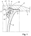
- FIG. 1 shows a detachable connection arrangement in a sectional view from a cylinder end (1) with a curved cover (2), which has an attached shoulder (8) on its outside.
- a recess (5) is incorporated in the sleeve (4) fixed to the open end of the cylinder (1) .
- the recess (5) are in Circumferential direction of several recesses (6), each with a contact surface (11) incorporated, against which the clamping elements (7) rest over the entire surface.
- tensioning means (9) between the shoulder (8) and a tension and the tensioning elements (7) during assembly Form fit between the sleeve, the clamping elements and the collar generated.
- Fig. 2 shows a perspective interior view of a section of the open end of a sleeve (4) with several in the recess (5) built-in recesses (6) for receiving the wedge-shaped
- Each clamping element has a contact surface (11).
- the incorporated Recesses (6) are arranged in the circumferential direction so that a web or the full sleeve wall thickness between each recess remains.
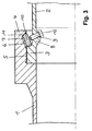
- Fig. 3 shows the longitudinal section of an unpaired connection with one the cylinder end (1) fixed sleeve (4) on the open End has a recess (5).
- the recess (5) points in the circumferential direction several recesses (6), each with a contact surface (11) for receiving and full-surface contact of the wedge-shaped clamping elements (7).
- Screws as tensioning means (9) during assembly Non-positive and positive locking between the sleeve (4), the clamping elements (7) and the federal government (3).
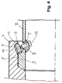
- FIG. 4 shows the longitudinal section of FIG. 3 as an exemplary embodiment connection shown with a consisting of individual segments Shoulder.
- the segments are in holes that are at right angles arranged to the cylinder wall and thus relatively easy to manufacture, inserted and welded.
- the end faces of the to be braced Components are arranged at an angle. This is e.g. to Absorption of high lateral forces or for central arrangement rotating components required.
- FIG. 5 shows in a longitudinal section a single-row, an inner ring (3 ') and outer ring (3 '') having a large roller bearing (to be braced Component) with its connection to the fixed (component 1) and rotatable connecting structure (component 2).
- a sleeve (4) is fixedly arranged at the open end Has recess (5).
- the recesses point in the circumferential direction several recesses (6), each with a contact surface (11) for receiving and full-surface contact of the wedge-shaped clamping elements (7).
- Screws as tensioning means (9) produce during assembly a positive and positive connection between the sleeve, the clamping elements (7), the bearing and the connecting structure.
- FIG. 6 shows a sectional illustration of an exemplary embodiment Detachable connection from a cylinder end (1) to a flat one Cap (2), on the outside of a shoulder (8).
- Sleeve (4) has a recess (5).
- In the turn (5) are recesses (6) in the circumferential direction, each with a contact surface (11) incorporated, against which the clamping elements (7) rest over the entire surface.
- Screws as bracing means (9) generate in the direction of the bracing axis (10) with the shoulder (8) of the closure cover (2), the tensioning elements (7) and the sleeve (4) a positive and positive connection between the clamped components.
- the interaction of all components enables the use of the radial rigidity of the flat cover, so that the rigidity of the entire connection increases becomes.
Landscapes
- Engineering & Computer Science (AREA)
- General Engineering & Computer Science (AREA)
- Mechanical Engineering (AREA)
- Mutual Connection Of Rods And Tubes (AREA)
- Clamps And Clips (AREA)
- Non-Disconnectible Joints And Screw-Threaded Joints (AREA)
- Joining Of Building Structures In Genera (AREA)
- Adornments (AREA)
- Quick-Acting Or Multi-Walled Pipe Joints (AREA)
- Mechanical Coupling Of Light Guides (AREA)
- Materials For Medical Uses (AREA)
- Diaphragms For Electromechanical Transducers (AREA)
Abstract
Description
- Fig.1
- eine Schnittdarstellung einer Verbindungsanordnung von einem Rohr- oder Zylinderende mit einem gewölbten Verschlußdeckel.
- Fig.2
- eine perspektivische Innenansicht eines Hülsenausschnittes.
- Fig.3
- einen Längsschnitt einer Verbindungsanordnung von zwei Rohr- oder Zylinderenden.
- Fig.4
- eine Verbindungsanordnung analog der Schnittdarstellung in Fig. 3, jedoch mit einer aus Einzelsegmenten ausgeführten Schulter.
- Fig.5
- ein mit den Anschlußkonstruktionen verspanntes Großwälzlager, dargestellt in einem Längsschnitt.
- Fig. 6
- eine Schnittdarstellung einer Verbindungsanordnung von einem Rohr- oder Zylinderende mit einem ebenen Verschlußdeckel.
- 1
- Rohr- / Zylinderenden oder zylindrische Anschlußkonstruktion
- 2
- zylindrische Anschlußkonstruktion oder dem Verwendungszweck entsprechend konstruktiv ausgebildeter Verschlußdeckel
- 3
- radial nach außen oder nach innen ausgebildeter Bund
- 4
- radial nach außen oder nach innen ausgebildete Hülse
- 5
- Ausdrehung in der Hülse zur axial übergreifenden Aufnahme eines Bundes
- 6
- in Umfangsrichung angeordnete Ausnehmungen in der Hülse zur Aufnahme der Spannelemente
- 7
- Spannelement
- 8
- angearbeitete oder aus mehreren Einzelsegmenten bestehende Schulter
- 9
- Mittel zum Erzeugen des Verspannungszustandes
- 10
- Verspannachse der Spannelemente
- 11
- Anlageflächen in den Ausnehmungen der Hülse zur vollflächigen Anlage der Spannelemente
- 12
- Anordnungs- und Wirkachse der Verspannmittel
Claims (11)
- Lösbare kraft- und formschlüssige Verbindungsanordnung für zwei an der Verbindungsstelle rotationssymmetrische, paarige oder unpaarige Bauteile,
bei einer paarigen Verbindungsanordnung mit einem radial nach außen oder innen vorspringenden Bund (3) oder Ring an dem einen Bauteil (1), mit einem radial nach außen oder innen vorspringenden Bund (3) oder Ring an dem anderen Bauteil (2), mit einer Hülse (4), die beide Bunde (3) oder Ringe axial übergreift und mit einer Anzahl von keilförmigen Spannelementen (7), die über dem Umfang verteilt jeweils zwischen einem der Bunde (3) oder Ringe und der Hülse (4) angeordnet sind, bei einer unpaarigen Verbindung mit einem radial nach außen oder innen vorspringenden Bund (3) oder Ring an dem einen Bauteil (2), mit einer an dem anderen Bauteil (1) ausgebildeten Hülse (4), die den Bund (3) oder Ring in einer an dem offenen Ende der Hülse (4) vorhandenen Ausdrehung (5) axial übergreift und mit einer Anzahl von keilförmigen Spannelementen (7), die über dem Umfang verteilt zwischen dem Bund (3) oder Ring und der Hülse (4) angeordnet sind,
dadurch gekennzeichnet,
daß das Bauteil (1) und/oder das Bauteil (2) eine Schulter (8) aufweist, daß die Schulter (8) aus ein- oder mehrteiligen, lösbar oder fest angeordneten Einzelsegmenten besteht, daß zwischen der Schulter (8) und den Spannelementen (7) über dem Umfang verteilt Mittel (9) angeordnet sind, die in Richtung ihrer Anordnungs- und Wirkachse (12) mit der Schulter (8) und den Spannelementen (7) derart zusammenwirken, daß sie diese in Richtung der Verspannachse (10) radial und axial zwischen dem Bund (3) oder Ring des jeweiligen Bauteils und der Hülse (4) verspannen. - Lösbare Verbindungsanordnung entsprechend dem Oberbegriff des Anspruchs 1
dadurch gekennzeichnet,
daß an jedem offenen Ende in der Hülse (4) über dem Umfang verteilt mehrere Ausnehmungen (6) angeordnet sind, daß jede dieser Ausnehmung (6) zur Aufnahme und Anlage eines keilförmigen Spannelementes (7) eine Anlagefläche (11) aufweist, daß der Winkel zwischen den Anlageflächen (11) bzw. der Keilflächen der anliegenden Spannelemente (7) und der jeweiligen Verspannachse (10) entsprechend den verwendeten Materialien eine Größe aufweist, der eine Haftreibung und somit eine Selbsthemmung der verspannten Bauteile nach dem Verspannvorgang sicherstellt und daß die Ausnehmungen (6) in Umfangsrichtung in einem Abstand zueinander oder direkt hintereinander angeordnet sind. - Lösbare Verbindungsanordnung entsprechend dem Oberbegriff des Anspruchs 1
dadurch gekennzeichnet,
daß die kennzeichnenden Merkmale des Anspruchs 1 gleichzeitig mit den kennzeichnenden Merkmalen des Anspruchs 2 zur Anwendung gelangen. - Verbindungsanordnung nach einem der Ansprüche 1 - 3, dadurch gekennzeichnet, daß die Mittel (9) Schrauben sind.
- Verbindungsanordnung nach Anspruch 4, dadurch gekennzeichnet, daß die Schrauben (Mittel 9) durch Bohrungen in den Spannelementen (7) in Richtung der Verspannachse (10) hindurchgehen und mit der Hülse (4) zusammenwirken.
- Verbindungsanordnung nach einem der Ansprüche 1 - 3, dadurch gekennzeichnet, daß die Mittel (9) hydraulisch, pneumatisch, elektrisch oder thermisch wirkende Aggregate oder weitere mechanisch wirkende Bauteile sind, die jeweils einzeln oder in Kombinationen zueinander angeordnet werden können.
- Verbindungsanordnung nach Anspruch 6, dadurch gekennzeichnet, daß die Mittel (9) lösbar oder fest miteinander, mit dem Bauteil (2) und/oder mit der Hülse (4) und/oder mit den Spannelementen (7) verbunden sind.
- Verbindungsanordnung nach einem der Ansprüche 1 - 7, dadurch gekennzeichnet, daß die an dem Bauteil (1) ausgebildete Hülse (4) lösbar mit dem Bauteil (1) verbunden ist.
- Verbindungsanordnung nach einem der Ansprüche 1 - 7, dadurch gekennzeichnet, daß die an dem Bauteil (1) ausgebildete Hülse (4) und der an dem Bauteil (2) angeordnete Bund (3) sowohl radial nach innen als auch radial nach außen ausgebildet sind.
- Verbindungsanordnung nach Anspruch 2, dadurch gekennzeichnet, daß das zu verspannende Bauteil jeweils der Innenring (3') oder der Außenring (3'') eines Großwälzlagers ist, wobei die Ausnehmungen (6) in der an dem Bauteil (1) ausgebildeten Hülse (4) radial nach außen und die Ausnehmungen (6) in der an dem Bauteil (2) ausgebildeten Hülse (4) radial nach innen angeordnet sind.
- Verbindungsanordnung nach einem oder mehreren der Ansprüche 1 - 10, dadurch gekennzeichnet, daß die Schulter (8) lösbar oder fest zusätzlich an der Hülse (4) oder nur an der Hülse (4) angeordnet ist.
Applications Claiming Priority (4)
| Application Number | Priority Date | Filing Date | Title |
|---|---|---|---|
| DE19858171 | 1998-12-16 | ||
| DE19858171 | 1998-12-16 | ||
| DE19958260 | 1999-12-03 | ||
| DE19958260A DE19958260A1 (de) | 1998-12-16 | 1999-12-03 | Lösbare Verbindung von rotationssymmetrischen Bauteilen |
Publications (2)
| Publication Number | Publication Date |
|---|---|
| EP1010931A1 true EP1010931A1 (de) | 2000-06-21 |
| EP1010931B1 EP1010931B1 (de) | 2001-10-24 |
Family
ID=26050801
Family Applications (1)
| Application Number | Title | Priority Date | Filing Date |
|---|---|---|---|
| EP99124682A Expired - Lifetime EP1010931B1 (de) | 1998-12-16 | 1999-12-11 | Lösbare Verbindung von rotationssymmetrischen Bauteilen |
Country Status (7)
| Country | Link |
|---|---|
| EP (1) | EP1010931B1 (de) |
| AT (1) | ATE207588T1 (de) |
| CA (1) | CA2292292A1 (de) |
| DE (1) | DE29921714U1 (de) |
| DK (1) | DK1010931T3 (de) |
| ES (1) | ES2166207T3 (de) |
| NO (1) | NO996222L (de) |
Cited By (6)
| Publication number | Priority date | Publication date | Assignee | Title |
|---|---|---|---|---|
| EP2050968A1 (de) * | 2007-10-19 | 2009-04-22 | Siemens Aktiengesellschaft | Druckbehälter mit einem Deckel |
| CN1670418B (zh) * | 2004-03-17 | 2010-09-08 | 霍尔特控制装置有限及两合公司 | 两个旋转对称件的连接装置和该连接装置的一组张紧件 |
| DE202012004119U1 (de) | 2012-04-12 | 2012-06-05 | Alfred Wilhelm Schlemenat | Lösbare Verbindung von rotationssymmetrischen Bauteilen |
| DE202018101223U1 (de) * | 2018-03-05 | 2019-06-06 | Evoguard Gmbh | Gehäuse für eine Kreiselpumpe, Kreiselpumpe mit Gehäuse und Abfüllanlage umfassend eine solche Kreiselpumpe |
| US10584816B2 (en) | 2015-05-26 | 2020-03-10 | MTU Aero Engines AG | Clamping device for joining flange pieces |
| CN114109841A (zh) * | 2020-08-31 | 2022-03-01 | 苏尔寿管理有限公司 | 用于输送流体的泵 |
Families Citing this family (7)
| Publication number | Priority date | Publication date | Assignee | Title |
|---|---|---|---|---|
| DE20015918U1 (de) * | 2000-09-13 | 2002-02-07 | Ing. Walter Hengst GmbH & Co. KG, 48147 Münster | Flanschverbindung zwischen einer Funktionseinheit einer Brennkraftmaschine und einem zugehörigen Montagesockel |
| DE202007013319U1 (de) | 2007-09-13 | 2007-12-20 | Schlemenat, Alfred W. | Lösbare kraft- und formschlüssige Verbindung einer Propellernabe und einem Verstellpropeller |
| DE102008055778A1 (de) | 2008-11-04 | 2010-05-06 | Schlemenat, Alfred W. | Offshore Gründung und Verfahren zur Montage |
| DE102010024294A1 (de) | 2010-06-18 | 2011-12-22 | Alfred W. Schlemenat | Lösbare kraft- und formschlüssige Verbindung von zwei zylindrischen Bauteilen, insbesondere Turm-/Monopile Verbindungen von Offshore-Windenergieanlagen |
| DE202010009860U1 (de) | 2010-07-05 | 2011-10-24 | Tec Artec Valves Gmbh & Co. Kg | Einspritzkühler |
| DE102010026116A1 (de) | 2010-07-05 | 2012-01-05 | Tec Artec Valves Gmbh & Co. Kg | Einspritzkühler |
| EP3940041A1 (de) | 2020-07-17 | 2022-01-19 | iGas energy GmbH | Reaktor zur überkritischen hydrothermalen vergasung von biomasse |
Citations (4)
| Publication number | Priority date | Publication date | Assignee | Title |
|---|---|---|---|---|
| DE1475860A1 (de) * | 1965-09-21 | 1969-03-27 | Stevens William Ernest | Rohrkupplung |
| DE1750069A1 (de) * | 1968-03-21 | 1971-01-14 | Sulzer Ag | Befestigungsvorrichtung fuer Elemente,insbesondere fuer Hochdruckpumpen |
| US3873138A (en) * | 1972-10-19 | 1975-03-25 | Caterpillar Tractor Co | Quick disconnect sealed coupling |
| EP0775863A1 (de) * | 1995-11-25 | 1997-05-28 | MAN Gutehoffnungshütte Aktiengesellschaft | Lösbare Verbindung von rotationssysmmetrischen Bauteilen |
-
1999
- 1999-12-03 DE DE29921714U patent/DE29921714U1/de not_active Expired - Lifetime
- 1999-12-11 AT AT99124682T patent/ATE207588T1/de active
- 1999-12-11 DK DK99124682T patent/DK1010931T3/da active
- 1999-12-11 ES ES99124682T patent/ES2166207T3/es not_active Expired - Lifetime
- 1999-12-11 EP EP99124682A patent/EP1010931B1/de not_active Expired - Lifetime
- 1999-12-15 NO NO19996222A patent/NO996222L/no not_active Application Discontinuation
- 1999-12-15 CA CA002292292A patent/CA2292292A1/en not_active Abandoned
Patent Citations (4)
| Publication number | Priority date | Publication date | Assignee | Title |
|---|---|---|---|---|
| DE1475860A1 (de) * | 1965-09-21 | 1969-03-27 | Stevens William Ernest | Rohrkupplung |
| DE1750069A1 (de) * | 1968-03-21 | 1971-01-14 | Sulzer Ag | Befestigungsvorrichtung fuer Elemente,insbesondere fuer Hochdruckpumpen |
| US3873138A (en) * | 1972-10-19 | 1975-03-25 | Caterpillar Tractor Co | Quick disconnect sealed coupling |
| EP0775863A1 (de) * | 1995-11-25 | 1997-05-28 | MAN Gutehoffnungshütte Aktiengesellschaft | Lösbare Verbindung von rotationssysmmetrischen Bauteilen |
Non-Patent Citations (1)
| Title |
|---|
| W.HAMPP: "WÄLZLAGERUNGEN, Berechnung und Gestaltung", 1971, SPRINGER-VERLAG, BERLIN(DE)/HEIDELBERG(DE)/NEW YORK(US), XP002133180 * |
Cited By (10)
| Publication number | Priority date | Publication date | Assignee | Title |
|---|---|---|---|---|
| CN1670418B (zh) * | 2004-03-17 | 2010-09-08 | 霍尔特控制装置有限及两合公司 | 两个旋转对称件的连接装置和该连接装置的一组张紧件 |
| EP2050968A1 (de) * | 2007-10-19 | 2009-04-22 | Siemens Aktiengesellschaft | Druckbehälter mit einem Deckel |
| WO2009053155A1 (de) * | 2007-10-19 | 2009-04-30 | Siemens Aktiengesellschaft | Druckbehälter mit einem deckel |
| US8425187B2 (en) | 2007-10-19 | 2013-04-23 | Siemens Aktiengesellschaft | Pressure vessel having a lid |
| DE202012004119U1 (de) | 2012-04-12 | 2012-06-05 | Alfred Wilhelm Schlemenat | Lösbare Verbindung von rotationssymmetrischen Bauteilen |
| DE102012007145A1 (de) | 2012-04-12 | 2013-10-17 | Alfred W. Schlemenat | Lösbare Verbindung von rotationssymmetrischen Bauteilen |
| US10584816B2 (en) | 2015-05-26 | 2020-03-10 | MTU Aero Engines AG | Clamping device for joining flange pieces |
| DE202018101223U1 (de) * | 2018-03-05 | 2019-06-06 | Evoguard Gmbh | Gehäuse für eine Kreiselpumpe, Kreiselpumpe mit Gehäuse und Abfüllanlage umfassend eine solche Kreiselpumpe |
| CN114109841A (zh) * | 2020-08-31 | 2022-03-01 | 苏尔寿管理有限公司 | 用于输送流体的泵 |
| EP3961039A1 (de) * | 2020-08-31 | 2022-03-02 | Sulzer Management AG | Pumpe zum fördern eines fluides |
Also Published As
| Publication number | Publication date |
|---|---|
| ES2166207T3 (es) | 2002-04-01 |
| ATE207588T1 (de) | 2001-11-15 |
| DK1010931T3 (da) | 2002-02-18 |
| NO996222L (no) | 2000-06-19 |
| EP1010931B1 (de) | 2001-10-24 |
| NO996222D0 (no) | 1999-12-15 |
| DE29921714U1 (de) | 2000-03-09 |
| CA2292292A1 (en) | 2000-06-16 |
Similar Documents
| Publication | Publication Date | Title |
|---|---|---|
| EP1010931B1 (de) | Lösbare Verbindung von rotationssymmetrischen Bauteilen | |
| DE3510926C2 (de) | Spannvorrichtung zum mechanischen Spannen von Befestigungselementen | |
| EP1194651B2 (de) | Baumaschine sowie fräswalze | |
| EP0775863B1 (de) | Lösbare Verbindung von rotationssysmmetrischen Bauteilen | |
| DE3345959C2 (de) | Zylinderkopfbefestigungskonstruktion | |
| DE102018108690A1 (de) | Mahlwalze und Walzenpresse | |
| DE2836395B1 (de) | Satzfraeser | |
| DE202012004119U1 (de) | Lösbare Verbindung von rotationssymmetrischen Bauteilen | |
| EP3017111A1 (de) | GROßZYLINDER-TROCKENWALZE SOWIE VERFAHREN ZUM HERSTELLEN EINER GROßZYLINDER-TROCKENWALZE | |
| DE102014209062A1 (de) | Radialgleitlager | |
| DE10112293C1 (de) | Großdrehlagerung | |
| DE19958260A1 (de) | Lösbare Verbindung von rotationssymmetrischen Bauteilen | |
| DE4326150A1 (de) | Vorrichtung zur axialen Festlegung von Bauteilen und ferner ein Verfahren zur axialen Festlegung von Bauteilen | |
| EP2391569B1 (de) | Treibscheiben-schachtfördermaschine | |
| EP1311760A1 (de) | Hydraulische radialkolbenmaschine | |
| EP0113810A1 (de) | Angetriebener Setzstock für Drehmaschinen | |
| DE4405593C1 (de) | Kühlluftführung für Treibscheiben-Schachtfördermaschinen | |
| DE29822922U1 (de) | Lösbare Verbindung von rotationssymmetrischen Deckelverschlüssen | |
| DE2352520B1 (de) | Hydrostatische Kolbenmaschine | |
| DE10112517C1 (de) | Großdrehlagerung mit Wälzkörpern | |
| DE20202463U1 (de) | Großdrehlagerung | |
| DE3329262C2 (de) | Rotationsmeißel | |
| EP0127053A2 (de) | Arbeitsgerät zum Bearbeiten der Schnittstelle eines Rohres | |
| DE102022004311A1 (de) | Festklemmeinrichtung und Verfahren zum Festklemmen eines Werkstückträgers oder Werkzeugträgers mittels der Festklemmeinrichtung | |
| DE3301964A1 (de) | Rotationsmeissel |
Legal Events
| Date | Code | Title | Description |
|---|---|---|---|
| PUAI | Public reference made under article 153(3) epc to a published international application that has entered the european phase |
Free format text: ORIGINAL CODE: 0009012 |
|
| AK | Designated contracting states |
Kind code of ref document: A1 Designated state(s): AT BE CH CY DE DK ES FI FR GB IE IT LI NL SE |
|
| 17P | Request for examination filed |
Effective date: 20000527 |
|
| 17Q | First examination report despatched |
Effective date: 20000720 |
|
| GRAG | Despatch of communication of intention to grant |
Free format text: ORIGINAL CODE: EPIDOS AGRA |
|
| AKX | Designation fees paid |
Free format text: AT BE CH CY DE DK ES FI FR GB IE IT LI NL SE |
|
| GRAG | Despatch of communication of intention to grant |
Free format text: ORIGINAL CODE: EPIDOS AGRA |
|
| GRAG | Despatch of communication of intention to grant |
Free format text: ORIGINAL CODE: EPIDOS AGRA |
|
| GRAH | Despatch of communication of intention to grant a patent |
Free format text: ORIGINAL CODE: EPIDOS IGRA |
|
| GRAH | Despatch of communication of intention to grant a patent |
Free format text: ORIGINAL CODE: EPIDOS IGRA |
|
| GRAA | (expected) grant |
Free format text: ORIGINAL CODE: 0009210 |
|
| AK | Designated contracting states |
Kind code of ref document: B1 Designated state(s): AT BE CH CY DE DK ES FI FR GB IE IT LI NL SE |
|
| PG25 | Lapsed in a contracting state [announced via postgrant information from national office to epo] |
Ref country code: CY Free format text: LAPSE BECAUSE OF NON-PAYMENT OF DUE FEES Effective date: 20011024 |
|
| REF | Corresponds to: |
Ref document number: 207588 Country of ref document: AT Date of ref document: 20011115 Kind code of ref document: T |
|
| REG | Reference to a national code |
Ref country code: CH Ref legal event code: EP |
|
| REG | Reference to a national code |
Ref country code: IE Ref legal event code: FG4D Free format text: GERMAN |
|
| REF | Corresponds to: |
Ref document number: 59900339 Country of ref document: DE Date of ref document: 20011129 |
|
| REG | Reference to a national code |
Ref country code: GB Ref legal event code: IF02 |
|
| GBT | Gb: translation of ep patent filed (gb section 77(6)(a)/1977) |
Effective date: 20020106 |
|
| REG | Reference to a national code |
Ref country code: CH Ref legal event code: NV Representative=s name: TROESCH SCHEIDEGGER WERNER AG |
|
| REG | Reference to a national code |
Ref country code: DK Ref legal event code: T3 |
|
| ET | Fr: translation filed | ||
| REG | Reference to a national code |
Ref country code: ES Ref legal event code: FG2A Ref document number: 2166207 Country of ref document: ES Kind code of ref document: T3 |
|
| PLBE | No opposition filed within time limit |
Free format text: ORIGINAL CODE: 0009261 |
|
| STAA | Information on the status of an ep patent application or granted ep patent |
Free format text: STATUS: NO OPPOSITION FILED WITHIN TIME LIMIT |
|
| 26N | No opposition filed | ||
| PGFP | Annual fee paid to national office [announced via postgrant information from national office to epo] |
Ref country code: DK Payment date: 20101210 Year of fee payment: 12 |
|
| PGFP | Annual fee paid to national office [announced via postgrant information from national office to epo] |
Ref country code: GB Payment date: 20101221 Year of fee payment: 12 |
|
| PGFP | Annual fee paid to national office [announced via postgrant information from national office to epo] |
Ref country code: SE Payment date: 20111223 Year of fee payment: 13 Ref country code: NL Payment date: 20111228 Year of fee payment: 13 Ref country code: IE Payment date: 20111228 Year of fee payment: 13 Ref country code: ES Payment date: 20111227 Year of fee payment: 13 Ref country code: FI Payment date: 20111214 Year of fee payment: 13 Ref country code: FR Payment date: 20120105 Year of fee payment: 13 |
|
| PGFP | Annual fee paid to national office [announced via postgrant information from national office to epo] |
Ref country code: BE Payment date: 20111229 Year of fee payment: 13 |
|
| PGFP | Annual fee paid to national office [announced via postgrant information from national office to epo] |
Ref country code: IT Payment date: 20111227 Year of fee payment: 13 |
|
| PGFP | Annual fee paid to national office [announced via postgrant information from national office to epo] |
Ref country code: AT Payment date: 20121212 Year of fee payment: 14 |
|
| BERE | Be: lapsed |
Owner name: *SCHLEMENAT ALFRED Effective date: 20121231 |
|
| REG | Reference to a national code |
Ref country code: NL Ref legal event code: V1 Effective date: 20130701 |
|
| PG25 | Lapsed in a contracting state [announced via postgrant information from national office to epo] |
Ref country code: SE Free format text: LAPSE BECAUSE OF NON-PAYMENT OF DUE FEES Effective date: 20121212 |
|
| REG | Reference to a national code |
Ref country code: DK Ref legal event code: EBP |
|
| GBPC | Gb: european patent ceased through non-payment of renewal fee |
Effective date: 20121211 |
|
| PG25 | Lapsed in a contracting state [announced via postgrant information from national office to epo] |
Ref country code: FI Free format text: LAPSE BECAUSE OF NON-PAYMENT OF DUE FEES Effective date: 20121211 |
|
| REG | Reference to a national code |
Ref country code: IE Ref legal event code: MM4A |
|
| REG | Reference to a national code |
Ref country code: FR Ref legal event code: ST Effective date: 20130830 |
|
| PG25 | Lapsed in a contracting state [announced via postgrant information from national office to epo] |
Ref country code: BE Free format text: LAPSE BECAUSE OF NON-PAYMENT OF DUE FEES Effective date: 20121231 |
|
| PG25 | Lapsed in a contracting state [announced via postgrant information from national office to epo] |
Ref country code: IE Free format text: LAPSE BECAUSE OF NON-PAYMENT OF DUE FEES Effective date: 20121211 Ref country code: NL Free format text: LAPSE BECAUSE OF NON-PAYMENT OF DUE FEES Effective date: 20130701 |
|
| PG25 | Lapsed in a contracting state [announced via postgrant information from national office to epo] |
Ref country code: FR Free format text: LAPSE BECAUSE OF NON-PAYMENT OF DUE FEES Effective date: 20130102 Ref country code: GB Free format text: LAPSE BECAUSE OF NON-PAYMENT OF DUE FEES Effective date: 20121211 |
|
| PG25 | Lapsed in a contracting state [announced via postgrant information from national office to epo] |
Ref country code: IT Free format text: LAPSE BECAUSE OF NON-PAYMENT OF DUE FEES Effective date: 20121211 |
|
| PG25 | Lapsed in a contracting state [announced via postgrant information from national office to epo] |
Ref country code: DK Free format text: LAPSE BECAUSE OF NON-PAYMENT OF DUE FEES Effective date: 20130102 |
|
| PGFP | Annual fee paid to national office [announced via postgrant information from national office to epo] |
Ref country code: CH Payment date: 20131219 Year of fee payment: 15 |
|
| REG | Reference to a national code |
Ref country code: ES Ref legal event code: FD2A Effective date: 20140307 |
|
| PG25 | Lapsed in a contracting state [announced via postgrant information from national office to epo] |
Ref country code: ES Free format text: LAPSE BECAUSE OF NON-PAYMENT OF DUE FEES Effective date: 20121212 |
|
| REG | Reference to a national code |
Ref country code: AT Ref legal event code: MM01 Ref document number: 207588 Country of ref document: AT Kind code of ref document: T Effective date: 20131211 |
|
| PG25 | Lapsed in a contracting state [announced via postgrant information from national office to epo] |
Ref country code: AT Free format text: LAPSE BECAUSE OF NON-PAYMENT OF DUE FEES Effective date: 20131211 |
|
| PGFP | Annual fee paid to national office [announced via postgrant information from national office to epo] |
Ref country code: DE Payment date: 20141211 Year of fee payment: 16 |
|
| REG | Reference to a national code |
Ref country code: CH Ref legal event code: PL |
|
| PG25 | Lapsed in a contracting state [announced via postgrant information from national office to epo] |
Ref country code: LI Free format text: LAPSE BECAUSE OF NON-PAYMENT OF DUE FEES Effective date: 20141231 Ref country code: CH Free format text: LAPSE BECAUSE OF NON-PAYMENT OF DUE FEES Effective date: 20141231 |
|
| REG | Reference to a national code |
Ref country code: DE Ref legal event code: R119 Ref document number: 59900339 Country of ref document: DE |
|
| PG25 | Lapsed in a contracting state [announced via postgrant information from national office to epo] |
Ref country code: DE Free format text: LAPSE BECAUSE OF NON-PAYMENT OF DUE FEES Effective date: 20160701 |