EP1010959A2 - Procédé et dispositif de traitement thermique d'une bande en déplacement continu par soufflage de vapeur - Google Patents
Procédé et dispositif de traitement thermique d'une bande en déplacement continu par soufflage de vapeur Download PDFInfo
- Publication number
- EP1010959A2 EP1010959A2 EP99122120A EP99122120A EP1010959A2 EP 1010959 A2 EP1010959 A2 EP 1010959A2 EP 99122120 A EP99122120 A EP 99122120A EP 99122120 A EP99122120 A EP 99122120A EP 1010959 A2 EP1010959 A2 EP 1010959A2
- Authority
- EP
- European Patent Office
- Prior art keywords
- steam
- web
- lock
- inflating
- continuous
- Prior art date
- Legal status (The legal status is an assumption and is not a legal conclusion. Google has not performed a legal analysis and makes no representation as to the accuracy of the status listed.)
- Granted
Links
- 238000007664 blowing Methods 0.000 title claims abstract description 8
- 238000000034 method Methods 0.000 title claims description 27
- 238000010438 heat treatment Methods 0.000 title claims description 17
- 239000000463 material Substances 0.000 claims abstract description 27
- 239000000109 continuous material Substances 0.000 claims abstract 9
- 238000011144 upstream manufacturing Methods 0.000 claims description 2
- 239000003570 air Substances 0.000 description 45
- 238000001035 drying Methods 0.000 description 9
- 238000009833 condensation Methods 0.000 description 4
- 230000005494 condensation Effects 0.000 description 4
- 239000012080 ambient air Substances 0.000 description 3
- 238000005192 partition Methods 0.000 description 3
- 230000035515 penetration Effects 0.000 description 3
- 238000000605 extraction Methods 0.000 description 2
- 230000001154 acute effect Effects 0.000 description 1
- 230000015572 biosynthetic process Effects 0.000 description 1
- 239000003795 chemical substances by application Substances 0.000 description 1
- 238000010276 construction Methods 0.000 description 1
- 238000001704 evaporation Methods 0.000 description 1
- 230000008020 evaporation Effects 0.000 description 1
- 238000000227 grinding Methods 0.000 description 1
- 238000009434 installation Methods 0.000 description 1
- 239000003921 oil Substances 0.000 description 1
- 238000002360 preparation method Methods 0.000 description 1
- 239000002904 solvent Substances 0.000 description 1
- 239000004753 textile Substances 0.000 description 1
- 238000007669 thermal treatment Methods 0.000 description 1
- 239000002699 waste material Substances 0.000 description 1
Images


Classifications
-
- D—TEXTILES; PAPER
- D06—TREATMENT OF TEXTILES OR THE LIKE; LAUNDERING; FLEXIBLE MATERIALS NOT OTHERWISE PROVIDED FOR
- D06B—TREATING TEXTILE MATERIALS USING LIQUIDS, GASES OR VAPOURS
- D06B23/00—Component parts, details, or accessories of apparatus or machines, specially adapted for the treating of textile materials, not restricted to a particular kind of apparatus, provided for in groups D06B1/00 - D06B21/00
- D06B23/14—Containers, e.g. vats
- D06B23/16—Containers, e.g. vats with means for introducing or removing textile materials without modifying container pressure
-
- D—TEXTILES; PAPER
- D06—TREATMENT OF TEXTILES OR THE LIKE; LAUNDERING; FLEXIBLE MATERIALS NOT OTHERWISE PROVIDED FOR
- D06C—FINISHING, DRESSING, TENTERING OR STRETCHING TEXTILE FABRICS
- D06C7/00—Heating or cooling textile fabrics
- D06C7/02—Setting
-
- F—MECHANICAL ENGINEERING; LIGHTING; HEATING; WEAPONS; BLASTING
- F26—DRYING
- F26B—DRYING SOLID MATERIALS OR OBJECTS BY REMOVING LIQUID THEREFROM
- F26B13/00—Machines and apparatus for drying fabrics, fibres, yarns, or other materials in long lengths, with progressive movement
- F26B13/005—Seals, locks, e.g. gas barriers for web drying enclosures
-
- F—MECHANICAL ENGINEERING; LIGHTING; HEATING; WEAPONS; BLASTING
- F26—DRYING
- F26B—DRYING SOLID MATERIALS OR OBJECTS BY REMOVING LIQUID THEREFROM
- F26B13/00—Machines and apparatus for drying fabrics, fibres, yarns, or other materials in long lengths, with progressive movement
- F26B13/10—Arrangements for feeding, heating or supporting materials; Controlling movement, tension or position of materials
Definitions
- the invention relates to a method for heat treating a web by inflation of steam according to the preamble of claim 1 and a corresponding device according to the preamble of claim 9.
- a suitable device hereinafter called steam dryer, has a vapor-tight housing with an inlet and an outlet slot and one Transport device for the web.
- the heat treatment can be a drying, a drying with a fixation or a include pure fixation. All fields of the steam dryer, or only some of the Fields that are operated with steam.
- the continuous webs to be treated are prefers textile webs. It can also be paper or film webs or the like.
- the Material webs are transported by a transport device, for example with tension chains a roller conveyor or with a screen belt, conveyed through the steam dryer.
- the Transport device can also be provided with nozzle boxes provided with air cushion nozzles have free-floating guidance of the web.
- DE 27 27 971 describes a device for the thermal treatment of a continuous moving web of goods known to reduce the entry of indoor air into a Treatment chamber on the outside of in a wall of the treatment chamber provided web inlet and outlet openings each have a nozzle system as a seal is provided.
- a nozzle system includes a first one adjacent the chamber opening A pair of nozzles connected to a point in the treatment chamber which is at a negative pressure is, as well as a subsequent second pair of nozzles, with the pressure side of a suction side Atmosphere connected fan is connected.
- Another drying installation namely for paper webs, is from DE-A 42 26 107 known.
- This drying system has a dryer with additional nozzle boxes on both sides of the entry and exit slots.
- the nozzle boxes are provided with nozzle openings, the blowing direction of which is directed at an acute angle to the web guide plane onto the inlet gap.
- To the nozzle boxes are sawtooth-shaped on average.
- the penetration of cold Ambient air through the inlet slit is supposed to be matched between Exit velocity of the blowing jets and that existing inside the dryer Have negative pressure prevented.
- the vacuum prevents it from escaping when drying volatile solvents.
- a steam dryer should be at overpressure operate.
- a path running through the devices for heat treatment distinguishing heat treatment device namely a hanging loop damper, in which the material web by means of supporting rods attached to a circulating chain in free hanging Grinding through the treatment is known from DE 29 51 299.
- This The hanging loop damper is equipped with an air or Provide steam lock. There are none about the construction and operation of the lock Information provided.
- a generic steam dryer in which the Steam is blown onto a continuously moving web and is constantly circulated the steam flow and also the web speed in a hanging loop damper much lower, i.e. the requirements for a lock are also lower.
- the object of the invention is a generic method for heat treating a continuous web of goods by inflating steam according to the preamble of Claim 1 and a corresponding generic device according to the preamble of claim 9 to develop so that if possible no air, neither air with Ambient temperature still heated air penetrates into the interior of the device. Moreover should avoid condensation of the steam in the entrance area on the web become.
- steam is additionally in a lock in front of the inlet slot of the Inflated housing on the web.
- the steam becomes the web surrounding air displaces, causing air to enter the interior of the housing is prevented.
- the web is inflated by the steam through the large heat capacity of the steam warmed up with high efficiency. This reduces the risk formation of condensate in the entrance area inside the housing.
- a steam speed of 20 to 40 m / s according to claim 2 ensures that the on Steam impinging on the material web displaces the air boundary layer and the entry of air into it Housing is avoided.
- part of the exhaust steam is fed into the lock according to claim 4. This saves an additional source of steam.
- Exhaust steam which is removed according to claim 5 from the front region of the device, is not or significantly less contaminated with oils from the preparation agents than it is from the rear of the device.
- heated air is blown onto the in the lock before the inflation Material web inflated. This leads to a preheating of the web and prevents it Touching steam emerging from the lock with cold ambient air, resulting in a Condensation of the steam would result.
- Slot nozzles allow a particularly intensive contact of the Steam or the heated air with the web and good heat transfer.
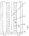
- Figure 1 shows the schematic representation of a side view of the first three fields Steam dryer according to the invention with a lock and those connected to the lock Cables.
- the lock is in an enlarged view in Figure 2 using a longitudinal section and in Figure 3 can be seen on the basis of a cross section along the line AA of Figure 2.
- a device according to the invention in other words a device according to the invention Steam dryer, has a vapor-tight, heat-insulated housing 1 with an inlet slot 2 and an outlet slot not shown in FIG. 1 and also not shown in FIG. 1 Transport device shown for a in the transport direction 3 through the steam dryer current web 4 on.
- Transport device shown for a in the transport direction 3 through the steam dryer current web 4 on.
- At least one field is a steam field 5 with a device for guiding steam in a circulating air process with a, dashed shown, circulating air fan 6 and a heating device, not shown, and with Nozzle boxes 7 with nozzle openings aimed at the web 4.
- One or more of the remaining fields can be air fields with a device for guiding Mostly heated air in the recirculation process also with a recirculation fan and with Be nozzle boxes with nozzle openings aimed at the material web.
- all six fields are steam fields 5, in each of which several, for Example two, above and below the web 4, across the web 4 extending nozzle boxes 7 are arranged.
- the manifold 9 leads to an exhaust fan 10.
- the inlet slot 2 is on a front wall 11 of the housing 1 and the outlet slot a rear wall of the housing 1 attached.
- the transport device forms inside the Housing 1 for the web 4 a horizontal transport plane on which the inlet slot 2nd and the outlet slot is arranged; d. H. it is designed so that the web 4 through the inlet slot 2, through the housing 1 and through the outlet slot on the horizontal Transport level is guided.
- a transport device with a tension chain through the inlet slot through the housing and through the outlet slot
- Tension chains arranged on a horizontal plane can also have a roller conveyor or a belt. It can also be used to levitate the Have material web, such as nozzle boxes with air cushion nozzles.
- the lock In front of the inlet slot 1 there is a lock with at least one steam chamber 12 Nozzle boxes 13 arranged.
- the lock has a vapor-tight, Heat-insulated housing 14, which is arranged in three in the transport direction 3 one behind the other Chambers, namely an air chamber 15, the steam chamber 12 and a suction chamber 16 is divided on.
- One to a steam exhaust line 8 from another steam field 5, here the second field, connected steam supply line 18 leads through a heat exchanger 19, through which one Air line 20 leads from one with its suction side to the atmosphere outside the Steam dryer open fan 21 goes out and behind the heat exchanger 19 to the Air chamber 15 of the lock is connected.
- a suction line 22 which leads to a fan, not shown leads, connected.
- the chambers 15, 12 and 16 of the lock have nozzle boxes.
- each chamber has a nozzle box 23 which extends over the entire width of the web, 13, 24 arranged in mirror image above and below the guide level of the web 4.
- the nozzle boxes 23, 13, 24 are through the housing 14 of the lock, two each Partitions 25, 26 and their bottom plates 27, 28, 29 are formed. Are on their side walls Openings 30 31, 32 are provided.
- the openings 30 31, 32 of the two opposite Nozzle boxes 23, 13, 24 of a chamber 15, 12, 16 are each, for example, by a line, not shown, connected together. In the respective line can the chambers 15, 12, 16 connected lines, namely the air line 21, the Steam supply line 17 and suction line 22 open out.
- the nozzle boxes 23 and 13 of the air chamber 15 and the steam chamber 12 point to the Floor plates 27, 28 attached slot nozzles 33, 34, the slot nozzles 34 of the Nozzle boxes 13 of the steam chamber 12 at an angle, counter to the transport direction 3 on the Goods web 4 are directed.
- the bottom plate 29 of the suction chamber 16 has Suction openings 35, for example round bores. The bottom plate 29 can be perforated his.
- the slot nozzles 33, 34 each have two side plates 35, 36 and their slots dividing Baffles 37 on.
- the side bleaches 35, 36 extend over a width which is at least that corresponds to the maximum width of the web 4; d. H. usually over the entire length of the Nozzle boxes 23 and 13.
- the guide plates 37 are arranged parallel to the transport direction 3 and divide the slots into equally large flow openings. They serve the purpose of equalization the flow of air and steam onto the web 4.
- the lock with the three chambers 15, 12 and 16 extends over the entire Web width; their length is approximately 1 m and their total height is approximately 0.8 m.
- the steam in the steam fields 5 performed in a circulating air process, with the continuous web 4 through the on Material web 4 directed nozzle openings of the nozzle boxes 7 steam inflated and the Steam after contact with the web 4 as exhaust steam with the help of the air circulation fan dissipated, heated to the desired temperature by the heating device and is fed again.
- the steam is after a start-up phase in which the superheated steam from supplied outside, constantly generated by drying the web 4. It is in Interior of the housing 1 before the inlet slot 2 and before the outlet slot an overpressure maintain.
- a part of the steam is after contact with the web 4 as waste steam through the Steam exhaust lines 8 deducted.
- Steam can be in the steam chamber 12 with the pressure around 0.2 bar, for example 0.5 bar the pressure in the device is inflated.
Landscapes
- Engineering & Computer Science (AREA)
- Textile Engineering (AREA)
- Mechanical Engineering (AREA)
- General Engineering & Computer Science (AREA)
- Treatment Of Fiber Materials (AREA)
- Drying Of Solid Materials (AREA)
Priority Applications (1)
| Application Number | Priority Date | Filing Date | Title |
|---|---|---|---|
| DK99122120T DK1010959T3 (da) | 1998-12-19 | 1999-11-05 | Fremgangsmåde og indretning til varmebehandling af en löbende varebane ved påblæsning af damp |
Applications Claiming Priority (2)
| Application Number | Priority Date | Filing Date | Title |
|---|---|---|---|
| DE19858839A DE19858839B4 (de) | 1998-12-19 | 1998-12-19 | Verfahren und Vorrichtung zum Wärmebehandeln einer durchlaufenden Warenbahn durch Aufblasen von Dampf |
| DE19858839 | 1998-12-19 |
Publications (3)
| Publication Number | Publication Date |
|---|---|
| EP1010959A2 true EP1010959A2 (fr) | 2000-06-21 |
| EP1010959A3 EP1010959A3 (fr) | 2001-09-12 |
| EP1010959B1 EP1010959B1 (fr) | 2005-03-16 |
Family
ID=7891820
Family Applications (1)
| Application Number | Title | Priority Date | Filing Date |
|---|---|---|---|
| EP99122120A Expired - Lifetime EP1010959B1 (fr) | 1998-12-19 | 1999-11-05 | Procédé et dispositif de traitement thermique d'une bande en déplacement continu par soufflage de vapeur |
Country Status (5)
| Country | Link |
|---|---|
| US (1) | US6282811B1 (fr) |
| EP (1) | EP1010959B1 (fr) |
| AT (1) | ATE291211T1 (fr) |
| DE (2) | DE19858839B4 (fr) |
| DK (1) | DK1010959T3 (fr) |
Cited By (1)
| Publication number | Priority date | Publication date | Assignee | Title |
|---|---|---|---|---|
| EP1055763A3 (fr) * | 1999-05-28 | 2002-01-30 | Babcock Textilmaschinen GmbH | Procédé et dispositif pour le traitement continu à la vapeur d'une étoffe textile pour le fixage des colorants réactifs sur des fibres naturelles |
Families Citing this family (11)
| Publication number | Priority date | Publication date | Assignee | Title |
|---|---|---|---|---|
| DE29909402U1 (de) | 1999-05-31 | 1999-08-12 | Babcock Textilmaschinen GmbH, 21220 Seevetal | Heißdampftrockner |
| US6631566B2 (en) * | 2000-09-18 | 2003-10-14 | Kimberly-Clark Worldwide, Inc. | Method of drying a web |
| DE10333483B4 (de) | 2003-07-22 | 2008-11-27 | Moenus Textilmaschinen Gmbh | Verfahren zur Wärmebehandlung einer Warenbahn und Behandlungsvorrichtung |
| DE10337644B3 (de) * | 2003-08-16 | 2005-05-25 | Elpo Gmbh Luft- Und Trocknungstechnik | Vorrichtung und Verfahren zur thermischen Behandlung von Bahnmaterial |
| SE536108C2 (sv) * | 2010-11-16 | 2013-05-07 | Andritz Tech & Asset Man Gmbh | Torklåda som innefattar åtminstone två zoner för torkning av en cellulosamassabana |
| US9217212B2 (en) * | 2011-01-21 | 2015-12-22 | Despatch Industries Limited Partnership | Oven with gas circulation system and method |
| CN104088110B (zh) * | 2014-07-18 | 2016-04-27 | 苏州市宏达集团有限公司 | 一种蒸汽定型机 |
| CN105318687B (zh) * | 2015-10-12 | 2017-12-15 | 江苏广盛源科技发展有限公司 | 一种用于纺织品烘干的设备和烘干方法 |
| CN105318690B (zh) * | 2015-10-12 | 2017-12-15 | 盐城帝佳妮服饰有限公司 | 一种用于纺织品烘干的设备和烘干方法 |
| CN105318689B (zh) * | 2015-10-12 | 2017-12-19 | 江苏广盛源科技发展有限公司 | 一种用于纺织品烘干的设备和烘干方法 |
| CN108589130A (zh) * | 2018-05-16 | 2018-09-28 | 湖州织里创塑塑料科技有限公司 | 一种蒸布机 |
Citations (3)
| Publication number | Priority date | Publication date | Assignee | Title |
|---|---|---|---|---|
| DE2727971A1 (de) | 1977-06-22 | 1979-01-11 | Brueckner Apparatebau Gmbh | Verfahren und vorrichtung zur thermischen behandlung einer warenbahn |
| DE4226107A1 (de) | 1992-08-07 | 1994-02-10 | Vits Maschinenbau Gmbh | Trocknungsanlage |
| DE19546344A1 (de) | 1995-12-12 | 1997-06-19 | Babcock Textilmasch | Vorrichtung zum Wärmebehandeln von durchlaufenden Warenbahnen |
Family Cites Families (15)
| Publication number | Priority date | Publication date | Assignee | Title |
|---|---|---|---|---|
| DE1460574A1 (de) * | 1964-03-18 | 1969-09-04 | Fleissner Gmbh | Abdichtung am Ein- und Auslauf von Druckkammern bei Textilbehandlungsanlagen |
| US3577653A (en) * | 1970-01-20 | 1971-05-04 | Beloit Corp | Web drying tunnel |
| DE2310195C2 (de) * | 1973-02-02 | 1983-01-20 | Vepa AG, 4125 Riehen, Basel | Dämpfer mit zumindest teilweise horizontaler Warenführung |
| DE2951299A1 (de) | 1979-12-20 | 1981-07-09 | Babcock Textilmaschinen Kg (Gmbh & Co), 2105 Seevetal | Waermebehandlungsvorrichtung, insbesondere haengeschleifendaempfer |
| GB2079913A (en) * | 1980-05-09 | 1982-01-27 | Crosfield Electronics Ltd | Web drying apparatus |
| DE3038791C2 (de) * | 1980-10-14 | 1985-08-01 | Lohmann Gmbh & Co Kg, 5450 Neuwied | Vorrichtung zum Trocknen von lösungsmittelhaltigem Material |
| DE3315755A1 (de) * | 1983-04-30 | 1984-10-31 | Babcock Textilmaschinen GmbH, 2105 Seevetal | Faserfangsieb inbes. fuer textiltrockner und dergl. |
| GB8405716D0 (en) * | 1984-03-05 | 1984-04-11 | Reed C M | Heat treatment apparatus |
| DE3743598A1 (de) * | 1987-12-22 | 1989-07-13 | Kramer Carl | Vorrichtung zur beruehrungsfreien abdichtung einer oeffnung gegen aus- oder eintretendes gas |
| FI78756C (fi) * | 1988-04-25 | 1989-09-11 | Valmet Paper Machinery Inc | Foerfarande och anordning vid torkning av en roerlig bana. |
| JP2552929B2 (ja) * | 1990-02-20 | 1996-11-13 | 富士写真フイルム株式会社 | 処理室壁のウエブ貫通部のガスシール装置 |
| DE4033637A1 (de) * | 1990-10-23 | 1992-04-30 | Babcock Textilmasch | Vorrichtung zur umluftmengenregelung bei waermebehandlungsvorrichtungen, wie trocknern und dgl. |
| US5105558A (en) * | 1991-03-28 | 1992-04-21 | Curry Donald P | Apparatus and process for drying cellulosic and textile substances with superheated steam |
| US5429303A (en) * | 1993-03-20 | 1995-07-04 | V.I.B. Apparatebau Gmbh | Steam spray tube with linear acceleration channel |
| DE19525545C1 (de) * | 1995-07-13 | 1996-09-26 | Babcock Textilmasch | Trockner für durchlaufende Textilbahnen |
-
1998
- 1998-12-19 DE DE19858839A patent/DE19858839B4/de not_active Expired - Fee Related
-
1999
- 1999-11-05 EP EP99122120A patent/EP1010959B1/fr not_active Expired - Lifetime
- 1999-11-05 AT AT99122120T patent/ATE291211T1/de not_active IP Right Cessation
- 1999-11-05 DE DE59911760T patent/DE59911760D1/de not_active Expired - Fee Related
- 1999-11-05 DK DK99122120T patent/DK1010959T3/da active
- 1999-12-14 US US09/460,695 patent/US6282811B1/en not_active Expired - Fee Related
Patent Citations (3)
| Publication number | Priority date | Publication date | Assignee | Title |
|---|---|---|---|---|
| DE2727971A1 (de) | 1977-06-22 | 1979-01-11 | Brueckner Apparatebau Gmbh | Verfahren und vorrichtung zur thermischen behandlung einer warenbahn |
| DE4226107A1 (de) | 1992-08-07 | 1994-02-10 | Vits Maschinenbau Gmbh | Trocknungsanlage |
| DE19546344A1 (de) | 1995-12-12 | 1997-06-19 | Babcock Textilmasch | Vorrichtung zum Wärmebehandeln von durchlaufenden Warenbahnen |
Cited By (1)
| Publication number | Priority date | Publication date | Assignee | Title |
|---|---|---|---|---|
| EP1055763A3 (fr) * | 1999-05-28 | 2002-01-30 | Babcock Textilmaschinen GmbH | Procédé et dispositif pour le traitement continu à la vapeur d'une étoffe textile pour le fixage des colorants réactifs sur des fibres naturelles |
Also Published As
| Publication number | Publication date |
|---|---|
| DE59911760D1 (de) | 2005-04-21 |
| ATE291211T1 (de) | 2005-04-15 |
| US6282811B1 (en) | 2001-09-04 |
| DE19858839B4 (de) | 2005-02-10 |
| EP1010959A3 (fr) | 2001-09-12 |
| EP1010959B1 (fr) | 2005-03-16 |
| DK1010959T3 (da) | 2005-07-04 |
| DE19858839A1 (de) | 2000-06-21 |
Similar Documents
| Publication | Publication Date | Title |
|---|---|---|
| EP0448983B1 (fr) | Dispositif pour le soufflage des deux côtés d'un matériau en forme de bande | |
| DE3910898A1 (de) | Verfahren und vorrichtung in einem kombinationstrockner, der aus einer gasinfraanordnung und einer wirbelanordnung besteht | |
| EP1010959B1 (fr) | Procédé et dispositif de traitement thermique d'une bande en déplacement continu par soufflage de vapeur | |
| DE2659736A1 (de) | Absaugvorrichtungen fuer maschinen | |
| DE3890457C2 (de) | Verfahren zum berührungsfreien Trocknen einer Papier- oder Kartonbahn | |
| DE102013015841B4 (de) | Oxidationsofen | |
| DE60006212T2 (de) | Apparat zur gasbehandlung von produkten | |
| EP3632640B1 (fr) | Installation de traitement pour une bande de matière flexible pouvant être guidée vers un four de traitement, en particulier feuille en matière plastique | |
| EP1055763A2 (fr) | Procédé et dispositif pour le traitement continu à la vapeur d'une étoffe textile pour le fixage des colorants réactifs sur des fibres naturelles | |
| WO2002093098A1 (fr) | Arret de gaz destine a des reacteurs faisant intervenir des canalisations de gaz | |
| DE19941760A1 (de) | Kühlzone einer Lackieranlage und Verfahren zum Betreiben einer solchen Kühlzone | |
| WO1994004740A1 (fr) | Dispositif de soufflerie pour bandes textiles | |
| DE2723222A1 (de) | Verfahren und vorrichtung zum trocknen von mit loesungsmittel behandelten gegenstaenden | |
| EP0141227B1 (fr) | Séchoir vertical | |
| EP0779486A1 (fr) | Dispositif pour le traitement par chaleur de bandes continues | |
| EP0471162B1 (fr) | Dispositif de séchage et/ou de fixation à convection | |
| EP2601467B1 (fr) | Dispositif de traitement thermique d'une bande de matière textile | |
| EP0658427B1 (fr) | Dispositif de séchage | |
| EP3719430A1 (fr) | Installation de séchage continu et procédé de séchage de pièces | |
| EP1070927B1 (fr) | Sécheur en continue de plaques ou de bandes | |
| WO2025036528A1 (fr) | Système de régulation de température permettant de réguler la température de pièces, et procédé de régulation de la température de pièces | |
| EP0063642B1 (fr) | Dispositif pour le séchage par air chaud de matières textiles | |
| WO2019174785A1 (fr) | Procédé et dispositif destinés à sécher des plaques | |
| EP2166298B1 (fr) | Séchoir pour bande de matériau | |
| EP4185825A1 (fr) | Séchoir pour sécher des panneaux de placage |
Legal Events
| Date | Code | Title | Description |
|---|---|---|---|
| PUAI | Public reference made under article 153(3) epc to a published international application that has entered the european phase |
Free format text: ORIGINAL CODE: 0009012 |
|
| AK | Designated contracting states |
Kind code of ref document: A2 Designated state(s): AT BE CH CY DE DK ES FI FR GB GR IE IT LI LU MC NL PT SE |
|
| AX | Request for extension of the european patent |
Free format text: AL;LT;LV;MK;RO;SI |
|
| PUAL | Search report despatched |
Free format text: ORIGINAL CODE: 0009013 |
|
| AK | Designated contracting states |
Kind code of ref document: A3 Designated state(s): AT BE CH CY DE DK ES FI FR GB GR IE IT LI LU MC NL PT SE |
|
| AX | Request for extension of the european patent |
Free format text: AL;LT;LV;MK;RO;SI |
|
| 17P | Request for examination filed |
Effective date: 20020312 |
|
| AKX | Designation fees paid |
Free format text: AT BE CH CY DE DK ES FI FR GB GR IE IT LI LU MC NL PT SE |
|
| 17Q | First examination report despatched |
Effective date: 20031128 |
|
| GRAP | Despatch of communication of intention to grant a patent |
Free format text: ORIGINAL CODE: EPIDOSNIGR1 |
|
| RAP1 | Party data changed (applicant data changed or rights of an application transferred) |
Owner name: MOENUS TEXTILMASCHINEN GMBH |
|
| GRAS | Grant fee paid |
Free format text: ORIGINAL CODE: EPIDOSNIGR3 |
|
| GRAA | (expected) grant |
Free format text: ORIGINAL CODE: 0009210 |
|
| AK | Designated contracting states |
Kind code of ref document: B1 Designated state(s): AT BE CH CY DE DK ES FI FR GB GR IE IT LI LU MC NL PT SE |
|
| PG25 | Lapsed in a contracting state [announced via postgrant information from national office to epo] |
Ref country code: NL Free format text: LAPSE BECAUSE OF FAILURE TO SUBMIT A TRANSLATION OF THE DESCRIPTION OR TO PAY THE FEE WITHIN THE PRESCRIBED TIME-LIMIT Effective date: 20050316 Ref country code: IE Free format text: LAPSE BECAUSE OF FAILURE TO SUBMIT A TRANSLATION OF THE DESCRIPTION OR TO PAY THE FEE WITHIN THE PRESCRIBED TIME-LIMIT Effective date: 20050316 Ref country code: GB Free format text: LAPSE BECAUSE OF FAILURE TO SUBMIT A TRANSLATION OF THE DESCRIPTION OR TO PAY THE FEE WITHIN THE PRESCRIBED TIME-LIMIT Effective date: 20050316 Ref country code: FI Free format text: LAPSE BECAUSE OF FAILURE TO SUBMIT A TRANSLATION OF THE DESCRIPTION OR TO PAY THE FEE WITHIN THE PRESCRIBED TIME-LIMIT Effective date: 20050316 |
|
| REG | Reference to a national code |
Ref country code: GB Ref legal event code: FG4D Free format text: NOT ENGLISH |
|
| RIN1 | Information on inventor provided before grant (corrected) |
Inventor name: VOTH, MARC-AUREL |
|
| REG | Reference to a national code |
Ref country code: CH Ref legal event code: EP |
|
| RIN2 | Information on inventor provided after grant (corrected) |
Inventor name: VOTH, MARC-AUREL |
|
| REG | Reference to a national code |
Ref country code: IE Ref legal event code: FG4D Free format text: GERMAN |
|
| REF | Corresponds to: |
Ref document number: 59911760 Country of ref document: DE Date of ref document: 20050421 Kind code of ref document: P |
|
| REG | Reference to a national code |
Ref country code: CH Ref legal event code: NV Representative=s name: BOVARD AG PATENTANWAELTE |
|
| PG25 | Lapsed in a contracting state [announced via postgrant information from national office to epo] |
Ref country code: GR Free format text: LAPSE BECAUSE OF FAILURE TO SUBMIT A TRANSLATION OF THE DESCRIPTION OR TO PAY THE FEE WITHIN THE PRESCRIBED TIME-LIMIT Effective date: 20050616 |
|
| PG25 | Lapsed in a contracting state [announced via postgrant information from national office to epo] |
Ref country code: ES Free format text: LAPSE BECAUSE OF FAILURE TO SUBMIT A TRANSLATION OF THE DESCRIPTION OR TO PAY THE FEE WITHIN THE PRESCRIBED TIME-LIMIT Effective date: 20050627 |
|
| REG | Reference to a national code |
Ref country code: DK Ref legal event code: T3 |
|
| NLV1 | Nl: lapsed or annulled due to failure to fulfill the requirements of art. 29p and 29m of the patents act | ||
| PG25 | Lapsed in a contracting state [announced via postgrant information from national office to epo] |
Ref country code: PT Free format text: LAPSE BECAUSE OF FAILURE TO SUBMIT A TRANSLATION OF THE DESCRIPTION OR TO PAY THE FEE WITHIN THE PRESCRIBED TIME-LIMIT Effective date: 20050907 |
|
| GBV | Gb: ep patent (uk) treated as always having been void in accordance with gb section 77(7)/1977 [no translation filed] |
Effective date: 20050316 |
|
| REG | Reference to a national code |
Ref country code: IE Ref legal event code: FD4D |
|
| PG25 | Lapsed in a contracting state [announced via postgrant information from national office to epo] |
Ref country code: CY Free format text: LAPSE BECAUSE OF FAILURE TO SUBMIT A TRANSLATION OF THE DESCRIPTION OR TO PAY THE FEE WITHIN THE PRESCRIBED TIME-LIMIT Effective date: 20051105 Ref country code: AT Free format text: LAPSE BECAUSE OF NON-PAYMENT OF DUE FEES Effective date: 20051105 |
|
| PGFP | Annual fee paid to national office [announced via postgrant information from national office to epo] |
Ref country code: DK Payment date: 20051124 Year of fee payment: 7 |
|
| PG25 | Lapsed in a contracting state [announced via postgrant information from national office to epo] |
Ref country code: MC Free format text: LAPSE BECAUSE OF NON-PAYMENT OF DUE FEES Effective date: 20051130 Ref country code: LU Free format text: LAPSE BECAUSE OF NON-PAYMENT OF DUE FEES Effective date: 20051130 Ref country code: BE Free format text: LAPSE BECAUSE OF NON-PAYMENT OF DUE FEES Effective date: 20051130 |
|
| PLBE | No opposition filed within time limit |
Free format text: ORIGINAL CODE: 0009261 |
|
| STAA | Information on the status of an ep patent application or granted ep patent |
Free format text: STATUS: NO OPPOSITION FILED WITHIN TIME LIMIT |
|
| 26N | No opposition filed |
Effective date: 20051219 |
|
| EN | Fr: translation not filed | ||
| PG25 | Lapsed in a contracting state [announced via postgrant information from national office to epo] |
Ref country code: DK Free format text: LAPSE BECAUSE OF NON-PAYMENT OF DUE FEES Effective date: 20061130 |
|
| REG | Reference to a national code |
Ref country code: DK Ref legal event code: EBP |
|
| BERE | Be: lapsed |
Owner name: MOENUS TEXTILMASCHINEN G.M.B.H. Effective date: 20051130 |
|
| PG25 | Lapsed in a contracting state [announced via postgrant information from national office to epo] |
Ref country code: SE Free format text: LAPSE BECAUSE OF FAILURE TO SUBMIT A TRANSLATION OF THE DESCRIPTION OR TO PAY THE FEE WITHIN THE PRESCRIBED TIME-LIMIT Effective date: 20050616 |
|
| PGFP | Annual fee paid to national office [announced via postgrant information from national office to epo] |
Ref country code: DE Payment date: 20071203 Year of fee payment: 9 |
|
| PGFP | Annual fee paid to national office [announced via postgrant information from national office to epo] |
Ref country code: IT Payment date: 20071130 Year of fee payment: 9 |
|
| PGFP | Annual fee paid to national office [announced via postgrant information from national office to epo] |
Ref country code: CH Payment date: 20071231 Year of fee payment: 9 |
|
| PG25 | Lapsed in a contracting state [announced via postgrant information from national office to epo] |
Ref country code: FR Free format text: LAPSE BECAUSE OF NON-PAYMENT OF DUE FEES Effective date: 20051130 |
|
| PG25 | Lapsed in a contracting state [announced via postgrant information from national office to epo] |
Ref country code: FR Free format text: LAPSE BECAUSE OF NON-PAYMENT OF DUE FEES Effective date: 20050316 |
|
| REG | Reference to a national code |
Ref country code: CH Ref legal event code: PL |
|
| PG25 | Lapsed in a contracting state [announced via postgrant information from national office to epo] |
Ref country code: IT Free format text: LAPSE BECAUSE OF NON-PAYMENT OF DUE FEES Effective date: 20081105 |
|
| PG25 | Lapsed in a contracting state [announced via postgrant information from national office to epo] |
Ref country code: LI Free format text: LAPSE BECAUSE OF NON-PAYMENT OF DUE FEES Effective date: 20081130 Ref country code: DE Free format text: LAPSE BECAUSE OF NON-PAYMENT OF DUE FEES Effective date: 20090603 Ref country code: CH Free format text: LAPSE BECAUSE OF NON-PAYMENT OF DUE FEES Effective date: 20081130 |