EP1010968A1 - Gerät zum ambulanten Registieren mit synchronisierter Nachrichtenübertragung zwischen zwei Prozessoren - Google Patents
Gerät zum ambulanten Registieren mit synchronisierter Nachrichtenübertragung zwischen zwei Prozessoren Download PDFInfo
- Publication number
- EP1010968A1 EP1010968A1 EP99124825A EP99124825A EP1010968A1 EP 1010968 A1 EP1010968 A1 EP 1010968A1 EP 99124825 A EP99124825 A EP 99124825A EP 99124825 A EP99124825 A EP 99124825A EP 1010968 A1 EP1010968 A1 EP 1010968A1
- Authority
- EP
- European Patent Office
- Prior art keywords
- processor
- rtp
- data
- line
- communication
- Prior art date
- Legal status (The legal status is an assumption and is not a legal conclusion. Google has not performed a legal analysis and makes no representation as to the accuracy of the status listed.)
- Granted
Links
Images




Classifications
-
- G—PHYSICS
- G01—MEASURING; TESTING
- G01D—MEASURING NOT SPECIALLY ADAPTED FOR A SPECIFIC VARIABLE; ARRANGEMENTS FOR MEASURING TWO OR MORE VARIABLES NOT COVERED IN A SINGLE OTHER SUBCLASS; TARIFF METERING APPARATUS; MEASURING OR TESTING NOT OTHERWISE PROVIDED FOR
- G01D9/00—Recording measured values
- G01D9/005—Solid-state data loggers
-
- A—HUMAN NECESSITIES
- A61—MEDICAL OR VETERINARY SCIENCE; HYGIENE
- A61B—DIAGNOSIS; SURGERY; IDENTIFICATION
- A61B5/00—Measuring for diagnostic purposes; Identification of persons
-
- A—HUMAN NECESSITIES
- A61—MEDICAL OR VETERINARY SCIENCE; HYGIENE
- A61B—DIAGNOSIS; SURGERY; IDENTIFICATION
- A61B5/00—Measuring for diagnostic purposes; Identification of persons
- A61B5/24—Detecting, measuring or recording bioelectric or biomagnetic signals of the body or parts thereof
-
- G—PHYSICS
- G16—INFORMATION AND COMMUNICATION TECHNOLOGY [ICT] SPECIALLY ADAPTED FOR SPECIFIC APPLICATION FIELDS
- G16H—HEALTHCARE INFORMATICS, i.e. INFORMATION AND COMMUNICATION TECHNOLOGY [ICT] SPECIALLY ADAPTED FOR THE HANDLING OR PROCESSING OF MEDICAL OR HEALTHCARE DATA
- G16H40/00—ICT specially adapted for the management or administration of healthcare resources or facilities; ICT specially adapted for the management or operation of medical equipment or devices
- G16H40/60—ICT specially adapted for the management or administration of healthcare resources or facilities; ICT specially adapted for the management or operation of medical equipment or devices for the operation of medical equipment or devices
- G16H40/63—ICT specially adapted for the management or administration of healthcare resources or facilities; ICT specially adapted for the management or operation of medical equipment or devices for the operation of medical equipment or devices for local operation
-
- Y—GENERAL TAGGING OF NEW TECHNOLOGICAL DEVELOPMENTS; GENERAL TAGGING OF CROSS-SECTIONAL TECHNOLOGIES SPANNING OVER SEVERAL SECTIONS OF THE IPC; TECHNICAL SUBJECTS COVERED BY FORMER USPC CROSS-REFERENCE ART COLLECTIONS [XRACs] AND DIGESTS
- Y10—TECHNICAL SUBJECTS COVERED BY FORMER USPC
- Y10S—TECHNICAL SUBJECTS COVERED BY FORMER USPC CROSS-REFERENCE ART COLLECTIONS [XRACs] AND DIGESTS
- Y10S128/00—Surgery
- Y10S128/92—Computer assisted medical diagnostics
Definitions
- the present invention relates to ambulatory recording, for medical and especially for diagnostic purposes, and particularly to an ambulatory recorder having synchronized communication between two processors.
- Various physiologic signals are often recorded and analyzed. These signals may included digestive pH, various digestive motility and pressure signals, EEG and EMG, to list only a few.
- Ambulatory recording and recorders are widely used to collect such data.
- Such devices include the Digitrapper Mk IIITM ambulatory recorder from Synectics Medical AB, the GastroScan IITM from Medical Instruments Corporation, and the SuperLoggerTM from Sandhill Scientific. These types of devices make it possible for patients to remain at home, or at the least be ambulant in a hospital setting while physiological data is recorded.
- the devices comprise a lightweight recorder in which the desired physiological data signals are temporarily stored and later downloaded for future analysis.
- ECG Electrocardiogram
- EEG Electroencephalogram
- pH and pressure Motility
- a recorder should be able to record among a programmable number of channels at a variety of programmable frequencies.
- RTP real time processor
- NRTP non real time processor
- the present invention in one aspect, provides an ambulatory medical recording system comprising:
- the invention provides an ambulatory medical recording system comprising:
- the invention provides an ambulatory medical recording system comprising:
- a method of communicating between a second processor and a first processor in a medical data recorder comprising the steps of:
- the first processor is a real time processor ("RTP") which handles the sampling function
- the second processor is a non real time processor ("NRTP") which handles the operating system function.
- RTP real time processor
- NRTP non real time processor
- a protocol for communication between the two processors is provided which permits the processors to have synchronized and, therefore, reliable communication.
- the reliability aspect of the communication scheme is highly important since the sampled and stored data is the primary purpose of the data recorder.
- the RTP operates only while sampling is occurring, while the NRTP only operates as needed. These as needed times include logging the sampled data into long term memory as well as re-configuring system settings such as sampling frequency or channels to be sampled. In this manner an ambulatory medical recording device may be fashioned which has minimal power consumption but with reliable data acquisition and recording while still offering many features.
- FIGS. are not necessarily to scale.
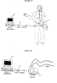
- FIG. 1A depicts an ambulatory recorder of the present invention.
- ambulatory recorder 1 of the present invention may be carried by a patient.
- the recorder may be either carried through a mounting in the back which fastens to a patient's belt 5, or the same mounting may be coupled to be carried using a shoulder harness (not shown).
- the recorder is coupled to the patient 4 through one or more sensing catheters 2.
- Sensing catheters may be positioned in any area of the patient's body, from which data is to be sensed, including the esophagus, as depicted in this figure.
- the ambulatory recorder of the present invention may be used to collect many or various types of data including gastrointestinal, neurological, as well as neuromuscular, EEG or EMG data.
- various sensing catheters which may be coupled to the device are manometry catheters and pH testing catheters, including the Synectics Medical AB, Sweden Model G 91-9 series of Multi use pH catheters; Synectics Medical AB Model G 91-2 series of Multi use pH catheters with perfusion port; or the Zinectics Inc., Salt Lake City, Utah disposable 24 pH catheter Model series G91-6 or G 91-7. While a single catheter 2 is shown depicted in this figure, the recorder further permits two separate sensors to be coupled to the device, as seen in FIG. 1B.
- the recorder may also communicate with a host PC 10 via an infra red data link facility through an IrDA connection 11, for example, a JETEYE ESI-57680 available form Extended Systems, Inc., Boise, Idaho, which connects with the recorder using the infra Red Data Association 1.1 Connection Protocol.
- IrDA connection 11 for example, a JETEYE ESI-57680 available form Extended Systems, Inc., Boise, Idaho, which connects with the recorder using the infra Red Data Association 1.1 Connection Protocol.
- the infra red data connection makes a link to infra red port 12 on the recorder.
- FIG. 1B illustrates a further manner in which the recorder 1 may also have an infra red data communication link made with a host PC.
- the infra red data communication data recorder may be further made when the recorder is not worn by the patient.
- the infra red data components and recorder case permit such a link to be made when the device is worn as shown in FIG. 1A as well as if the device is merely removed from the patient and positioned in proximity to mouse 11.
- FIG. 2 is a block diagram of the data recording system shown in FIG. 1B.
- recorder 1 features a battery 20 which is coupled to the signal conditioning /data acquisition block that is driven by a real time processor 21, the battery is coupled as well to a non-real time processor 22 that runs the application.
- real time processor 21 is a lower power processor which is used to sample data which is received from sensor input 23 by a sensor attached thereto (not shown in this FIG.).
- Sampling is achieved through the signal conditioning providing an excitation to the sensor coupled to sensor input 23.
- excitation voltage is often used to power and, thus, permit sensing to occur in a variety of different types of sensors, including pressure sensors, as is well known in the art.
- the sampling and sensing controls are provided by the real time processor 21.
- Real time processor also drives an LED indicator 25 to show the system is running even when the screen is off.
- this processor is coupled to second non-real time processor 22.
- Second processor 22 is provided primarily to perform those high processing operations associated with multitasking, graphical user interface, floating point calculation, Infra Red communication and long term memory storage.
- second processor is primarily provided to operate a Windows CE operating system as well as one or more embedded applications, as depicted.
- this processor is coupled to audible buzzer 31 as well as keyboard controls 32, a screen 33 and non-volatile memory 30.
- Non-volatile memory provides a long term memory for the device such that data can be recorded and preserved even if power is lost.
- the keyboard controls possesses a series of four push buttons, each of which provide one or more different types of system inputs, as provided by the Windows CETM operating system, available from Microsoft Corporation, Redmond, Washington.
- the recorder features an infra red port 35 to communicate with the host PC.
- the infra red connection permits the recorder 1 to receive and exchange data with host PC 10.
- Host PC includes both a Windows 98TM operating system available from Microsoft Corporation, Redmond, Washington, as well as one or more host applications. Host applications permit the treatment of the recorded values and help for diagnostics.
- the real time processor (“RTP") is the model PIC16LC67 from Microchip Technology Inc., Chandler, Arizona; the non real time processor (“NRTP”) is the model ElanSC400 from Advanced Micro Devices, Inc. Sunnyvale, California; and non-volatile memory is the model Minicard AMMCL004AWP from Advanced Micro Devices, Inc. Sunnyvale, California.
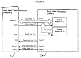
- FIG. 3 shows the signal lines used for the communication between the two processors.
- NRTP and RTP communicate along the following lines:
- Data bus 3e transfers data (this term is used in its broadest meaning and may include values, commands, argument, information, etc. ) between RTP and NRTP. In the preferred embodiment this is an 8 bit bus, although other sizes may be used.
- Write line 3f driven by the NRTP, writes data into the internal register A 3c of the RTP.
- Read line 3g driven by the NRTP, reads into the internal register B 3d of the RTP.
- Interrupt line 3h is driven by the RTP to interrupt the NRTP and signify that a command is available on its internal register B 3d of the RTP.
- Flip-flop line 3i is driven by the RTP in order to "synchronize" the transfer between the two processors.
- the operation of flip-flop line 3i line in order to synchronize the communication between the two processors will be made more clear below, but the flip-flop basically functions as a signal, indicating to the NRTP that there is something which has been sent either from or to the RTP.
- flip-flop line 3i has two functions, the particular function provided depends upon where within the communication protocol or sequence you are: First, the flip-flop may signal there is something to read in the internal register B of RTP. Secondly, the flip flop may signal that the data that the NRTP wrote in the internal register A has been read.
- the busy line 3j driven by the RTP signals to the NRTP that the RTP is busy doing something and that is not able to communicate. It should be understood that the lines are shown as discrete individual pathways for communication, although a common communication data bus may be provided as a pathway of communication.
- Busy line 3j is also important to the operation of the device.
- the RTP is running a real time single task software; while the NRTP is running a non-real time multitasking operating system and application with priorities.
- communication with the RTP could be started by several tasks at the same time, creating confusion in the exchange of data between the processors.
- Busy line 3j prevents such confusion by giving feedback to the NRTP that a communication session is in progress.
- the device further ensures reliable communication between the processors may occur through a time out feature.
- each processor checks that the other one responds in a certain range of time (i.e. before a certain time out). If the time out is exceeded the communication is considered failing.
- This feature is illustrated in FIGS. 5-7, shown below.
- the response time of the RTP is reasonably fast (several microseconds) since it runs a single task. Therefore the RTP time out can be of 100 micro seconds.
- the latency on the NRTP side on the other hand, can vary from several hundred micro seconds to milliseconds, since it runs a pre-emptive operating system. Nevertheless by experience, setting the NRTP time out at 20 milliseconds yields acceptable operation of the device. Of course, other values may also be selected, depending of what constitutes acceptable operation of the device, which may vary depending on the signals to be recorded.
- the time out is set as follows.
- the NRTP returns an error due to a time out occurring prior to a responding communication from the RTP, then the device returns an error in the application, the application being a user application run on the NRTP. After such an error is detected the communication is again restarted. Should a pre-selected number of time outs be experienced, 5 in a row in the preferred embodiment, then the device disables itself and sends out a "service me" command to the user through the display.
- FIG. 4 depicts the flowchart of the communication protocol.
- the communication always starts by one of the processors sending data or a command to the other one; and then, according to the data or command, the two processors exchange values until the end of communication.
- the communication can be divided into several modules.
- the NRTP ELAN processor
- the RTP PIC processor
- the communication is checked to ensure it is working properly. This is done through the provision of the time out as well as the reading back to the processor of the data that processor sent to the other processor, discussed above. If any communication failure happens 4h, communication is ended 4g. Moreover, upon detection of a communication failure, several events may occur. On the NRTP (ELAN processor) side, the application gives a feedback to the user that the second processor is not responding. On the RTP (PIC processor) side, it can ignore the failure or force the NRTP (ELAN processor) to restart. A suitable method for initiating a restart may be seen in the patent application of the same inventors filed on this same day and entitled "Ambulatory Recorder Having a Communication Watchdog between Two Processors" (Our ref. P-8142 CIP #2).
- Example 1 The steps in the communication where the NRTP wants the sampled value of a pH channel:
- Example 2 The steps in the communication where the RTP wants to download its buffer of samples to non-volatile memory.
- communication between the two processors may be facilitated through the series of modules shown in FIG. 4.
- a reliable and systematic method of communicating between the two processors may be fashioned and kept synchronized, even though the processors may be operating in differing time domains, i.e. a real time processor (RTP, e.g. the PIC Processor) and a non-real time processor (NRTP, e.g. the ELAN Processor).
- RTP real time processor
- NRTP non-real time processor
- FIG. 5 shows the flowchart of the steps used in the module "Command from the ELAN to the PIC" depicted as 4c in FIG. 4
- step 5a communication starts by the NRTP (ELAN processor) writing a command in the internal register A of the RTP (PIC processor).
- step 5b this causes, in turn, the RTP (PIC processor) to read that command in its internal register A.
- the RTP (PIC processor) at this time also rises a busy line (seen as 3j in FIG. 3) to prevent other attempts to write commands into it by other tasks being carried out in the NRTP(ELAN processor).
- step 5c the RTP (PIC processor) checks then if the command is known.
- the RTP PIC processor
- the RTP PIC processor
- the NRTP Ethernet processor
- the NRTP is waiting for the flip-flop line 3i (seen in FIG. 3) to flip in a time less than the RTP (PIC processor) time out 5i. If the time required to flip the line exceeds a pre-selected allowed time, then a communication failure is deemed to occur. At this point the recorder may reset itself, a suitable method for initiating a restart may be seen in the patent application of the same inventors filed on this same day and entitled "Ambulatory Recorder Having a Communication Watchdog between Two Processors" (Our ref. P-8142 CIP #2).
- the NRTP ELAN processor
- the NRTP Ethernet processor
- the NRTP reads the internal register B and checks the returned command. If the returned command is a NACK, then the communication stops (this is because the selected version of the RTP (PIC processor) does not know this new command, although other actions upon receipt of a NACK may be fashioned).
- the RTP PIC processor
- the RTP knows how many values on both sides have to be exchanged and the communication can continue on both sides (busy line 3j of FIG. 3 stays high).
- the RTP PIC processor
- NRTP ELAN processor
- NRTP Ethernet processor
- any of the above-mentioned actions may be initiated (e.g. device reset.)
- FIG. 6 shows the flowchart of module "Command from the PIC to the ELAN" seen as 4c in FIG. 4.
- step 6a communication begins by the RTP (PIC processor) writing a command in its internal register B.
- the RTP (PIC processor) rises the busy line to prevent other attempts to write commands into it by other tasks and actives the interrupt line.
- step 6b the NRTP (ELAN processor) is interrupted and executes an interrupt service routine, which will read the command in the internal register B. At this time the RTP (PIC processor) also notices the read and the interrupt line becomes inactive.
- step 6c the NRTP (ELAN processor) checks if the command is known.
- the NRTP ELAN processor
- step 6d the NRTP (ELAN processor) proceeds to step 6d and writes back the same command in the internal register A.
- the NRTP ELAN processor
- step 6e writes back a NACK (non-acknowledge command signal).
- the RTP PIC processor
- the RTP PIC processor
- the RTP PIC processor
- the RTP reads its internal register A and checks the return command. If it is a NACK (non-acknowledge command signal), then the communication stops (this version of the application on the NRTP (ELAN processor) does not know this new command) whereupon the device proceeds to step 4g. If it is the same command, the NRTP (ELAN processor) knows how many values on both sides have to be exchanged and the communication can continue, seen as step 6g.
- NACK non-acknowledge command signal
- the RTP PIC processor
- the NRTP ELAN processor
- the RTP PIC processor
- the NRTP ELAN processor
- the recorder may reset itself, a suitable method for initiating a restart may be seen in the patent application of the same inventors filed on this same day and entitled "Ambulatory Recorder Having a Communication Watchdog between Two Processors" (Our ref. P-8142 CIP #2).
- FIG. 7 shows the flowchart of module "Value from the ELAN to the PIC" depicted as 4e in FIG. 4.
- the NRTP ELAN processor
- the NRTP has one or more values to be passed to the RTP (PIC processor).
- the NRTP ELAN processor
- the NRTP writes a value in the internal register A of the RTP (PIC processor).
- the RTP PIC processor
- the NRTP (ELAN processor) is waiting for that line to flip in a time less than the RTP (PIC processor) time out (step 7i). If it exceeds the allowed time, we get a communication failure. At this point any of the above-mentioned actions may be initiated (e.g. device reset.)
- the NRTP (ELAN processor) reads the internal register B and checks the return value (step 7f). If it is different the communication stops (bad transfer of value) and the device proceeds to the step 4g depicted here and in FIG. 4. If it is the same, the NRTP (ELAN processor) checks if it has more values to passed (step 7g). If it is the case it returns to state 7b. If not the communication can continue according to the protocol (step 7h).
- the RTP PIC processor
- NRTP ELAN processor
- NRTP Ethernet processor
- any of the above-mentioned actions may be initiated (e.g. device reset).
- FIG. 8 shows the flowchart of module "Value from the PIC to the ELAN" depicted as 4f in FIG. 4.
- the RTP PIC processor
- the RTP PIC processor
- the NRTP Ethernet processor
- the NRTP is waiting for that line to flip in a time less than the RTP (PIC processor) time out (step 8j). If it exceeds the allowed time, then a communication failure is deemed to occur.
- the NRTP (ELAN processor) reads the internal register B and writes back the same value in the internal register A (step 8c). As seen before that causes an interrupt inside the RTP (PIC processor) which will read back the value (step 8e).
- the RTP (PIC processor) surveys how long it takes for the NRTP (ELAN processor) to write back the value (step 8I). This has to happen before the NRTP (ELAN processor) time out or else a communication failure is deemed to occur.
- the RTP (PIC processor) checks the return value (step 8f). If it is different the communication stops (bad transfer of value) (step 4g shown here as well as in FIG. 4). If it is the same, the RTP (PIC processor) checks if it has more values to pass (step 8g).
- any of the above-mentioned actions may be initiated (e.g. device reset).
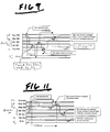
- FIGS. 9-12 depict examples of the device operation and particularly of the status of the lines between the PIC and the ELAN as commands are sent between the processors.
- FIG. 9 depicts the status of the lines between the “RTP (PIC processor)” and the “NRTP (ELAN processor)” as a transfer of command is made from the “NRTP (ELAN processor)” to the “RTP (PIC processor)".
- RTP PIC
- FIGS. 9-12 depict examples of the device operation and particularly of the status of the lines between the PIC and the ELAN as commands are sent between the processors.
- FIG. 9 depicts the status of the lines between the "RTP (PIC processor)” and the “NRTP (ELAN processor)” as a transfer of command is made from the “NRTP (ELAN processor)” to the “RTP (PIC processor)".
- the “NRTP (ELAN processor)” wants to begin a communication or transaction with the “RTP (PIC processor)” it writes the command on "ELAN WR” corresponding with line
- the command read back is not the same, then it is defined as a NACK (not acknowledged) and it means the "RTP (PIC processor)" cannot perform the command and a communication failure is deemed to occur. At this point, any of the above-mentioned actions may be initiated (e.g. device reset). If the command read back by the "NRTP (ELAN processor)" is the same, however, communication may occur and the "NRTP (ELAN processor)" may present its first argument.
- FIG. 10 depicts the status of the lines between the "RTP (PIC processor)" and the “NRTP (ELAN processor)” as an argument is presented from the “NRTP (ELAN processor)” to the “RTP (PIC processor)".
- a value 1 is written by the "NRTP (ELAN processor)” on line 3f.
- This is subsequently read by the “RTP (PIC processor)” from the “NRTP (ELAN processor)".
- this occurs on line PIC RD which is within the data bus 3e (referring to FIG. 3).
- this value is written by the "RTP (PIC processor)” back to the "NRTP (ELAN processor)" on line PIC WR.
- the flip-flop is set high.
- the "NRTP (ELAN processor)” reads along line 3g the writing from the "RTP (PIC processor)". If what the "NRTP (ELAN processor)” reads back is the same then the transfer is okay and communication may occur. This is shown in this figure as a subsequent value written by the "NRTP (ELAN processor)" on line 3f back to the "RTP (PIC processor)", seen here as value N. At this point the steps of communication are again repeated such that subsequent values from the "NRTP (ELAN processor)" may be read and transferred to the "RTP (PIC processor)".
- FIG. 11 depicts the status of the lines between the "RTP (PIC processor)” and the “NRTP (ELAN processor)” when a command is transferred from the “RTP (PIC processor)” to the “NRTP (ELAN processor)".
- the "RTP (PIC processor)” wants to start a communication or transaction, the “RTP (PIC processor)” must interrupt the “NRTP (ELAN processor)”. This is sent as a command seen at line PIC WR which, as discussed above, is part of data bus 3e shown in FIG. 3. This command, sent from the "RTP (PIC processor)", sets the interrupt high, seen here as line 3h.
- the "NRTP (ELAN processor)” will read the command upon servicing the interrupt, at which point it reads the command and checks to determine if it is a known command. Once the command is read the "NRTP (ELAN processor)” sets the interrupt low and the “NRTP (ELAN processor)” writes the command back on line 3f to the "RTP (PIC processor)". Thereafter, the “RTP (PIC processor)” reads this returned command from the "NRTP (ELAN processor)" at line PIC RD which, as discussed above, is part of data bus 3e. If the command read back by the "RTP (PIC processor)" is the same, the command is acknowledged and communication may begin.
- the busy line 3j is set high to inhibit further communication from the "NRTP (ELAN processor)" to the "RTP (PIC processor)". If the command read back by the "RTP (PIC processor)" is not the same then a NACK is signaled and a communication failure is deemed to occur. As seen, when a NACK is detected the busy line may be returned low.
- FIG. 12 depicts the status of the lines between the "RTP (PIC processor)” and the “NRTP (ELAN processor)” during the transfer of a value from the “RTP (PIC processor)” to the “NRTP (ELAN processor)".
- the “RTP (PIC processor)” begins the transfer of value by writing along PIC WR line (which is part of the data bus 3e shown in FIG. 3). Shortly after writing on this line the “RTP (PIC processor)” also flop-flops line 3I high.
- the "NRTP (ELAN processor)" thereafter, reads what the “RTP (PIC processor)” has written through line 3g and again writes back this value to the "RTP (PIC processor)” at line 3f.
- RTP PIC processor
- any of the above-mentioned actions may be initiated (e.g. device reset).
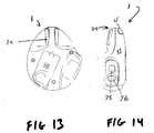
- FIG. 13 is a back view of the recorder shown in FIG. 2.
- recorder 1 features a belt loop 74 which may be used to mount the recorder to a patient using either the patient's belt or the shoulder strap.
- FIG. 14 is a side view of recorder shown in FIG. 2. As further seen in this view, housing 55 features a pair of sensor inputs 75 and 76. In the preferred embodiment, input 75 is for a pH catheter while input 76 is for a pressure measuring catheter.
- the present invention concerns an ambulatory recorder, for medical and especially for diagnostic purposes, and particularly to an ambulatory recorder having synchronized communication between two processors.
- the recorder preferably features two processor which are of differing architectures - the first processor being a real time processor (RTP) which handles the sampling function, while the second processor being a non real time (NRTP) processor which handles the operating system function.
- RTP real time processor
- NRTP non real time
- the invention may also be used with two identical processors, such as two real time processors, but where only one of the processors operates while needed, such as to control the device interface and/or operating system. In this manner the invention, thus, ensures communication between even two identical processors will be dependable, reliable and accurate.
- the invention further includes a protocol for communication between the two processors which permits the processors to have synchronized and safe communication. Further, the invention may also be used within a single mixed signal mixed processor, if desired as well as in a recorder featuring three or more processors.
Landscapes
- Health & Medical Sciences (AREA)
- Life Sciences & Earth Sciences (AREA)
- Engineering & Computer Science (AREA)
- Biomedical Technology (AREA)
- Medical Informatics (AREA)
- Public Health (AREA)
- General Health & Medical Sciences (AREA)
- Physics & Mathematics (AREA)
- Animal Behavior & Ethology (AREA)
- Veterinary Medicine (AREA)
- Molecular Biology (AREA)
- Surgery (AREA)
- Pathology (AREA)
- Biophysics (AREA)
- Heart & Thoracic Surgery (AREA)
- General Physics & Mathematics (AREA)
- Business, Economics & Management (AREA)
- General Business, Economics & Management (AREA)
- Epidemiology (AREA)
- Primary Health Care (AREA)
- Measuring And Recording Apparatus For Diagnosis (AREA)
- Computer And Data Communications (AREA)
- Hardware Redundancy (AREA)
- Debugging And Monitoring (AREA)
Applications Claiming Priority (4)
| Application Number | Priority Date | Filing Date | Title |
|---|---|---|---|
| US237926 | 1981-02-25 | ||
| US21056798A | 1998-12-14 | 1998-12-14 | |
| US210567 | 1998-12-14 | ||
| US09/237,926 US6245013B1 (en) | 1998-12-14 | 1999-01-27 | Ambulatory recorder having synchronized communication between two processors |
Publications (2)
| Publication Number | Publication Date |
|---|---|
| EP1010968A1 true EP1010968A1 (de) | 2000-06-21 |
| EP1010968B1 EP1010968B1 (de) | 2005-09-07 |
Family
ID=26905291
Family Applications (1)
| Application Number | Title | Priority Date | Filing Date |
|---|---|---|---|
| EP99124825A Expired - Lifetime EP1010968B1 (de) | 1998-12-14 | 1999-12-14 | Gerät zum ambulanten Registrieren mit synchronisierter Nachrichtenübertragung zwischen zwei Prozessoren |
Country Status (4)
| Country | Link |
|---|---|
| US (1) | US6245013B1 (de) |
| EP (1) | EP1010968B1 (de) |
| AT (1) | ATE304161T1 (de) |
| DE (1) | DE69927116T2 (de) |
Cited By (3)
| Publication number | Priority date | Publication date | Assignee | Title |
|---|---|---|---|---|
| WO2002041772A1 (en) * | 2000-11-22 | 2002-05-30 | Medtronic, Inc. | System and method for deriving a virtual ecg or egm signal |
| EP2689720A1 (de) * | 2012-07-24 | 2014-01-29 | Nihon Kohden Corporation | Vorrichtung zum Messen von Lebenszeichen |
| EP2919141A3 (de) * | 2014-03-13 | 2017-08-09 | Nihon Kohden Corporation | Messung biologischer Informationen und Anzeigevorrichtung |
Families Citing this family (51)
| Publication number | Priority date | Publication date | Assignee | Title |
|---|---|---|---|---|
| AU5405798A (en) * | 1996-12-30 | 1998-07-31 | Imd Soft Ltd. | Medical information system |
| US7454359B2 (en) * | 1999-06-23 | 2008-11-18 | Visicu, Inc. | System and method for displaying a health status of hospitalized patients |
| US7433827B2 (en) | 1999-06-23 | 2008-10-07 | Visicu, Inc. | System and method for displaying a health status of hospitalized patients |
| US8175895B2 (en) * | 1999-06-23 | 2012-05-08 | Koninklijke Philips Electronics N.V. | Remote command center for patient monitoring |
| US7475019B2 (en) * | 1999-11-18 | 2009-01-06 | Visicu, Inc. | System and method for physician note creation and management |
| US7395216B2 (en) | 1999-06-23 | 2008-07-01 | Visicu, Inc. | Using predictive models to continuously update a treatment plan for a patient in a health care location |
| US7315825B2 (en) * | 1999-06-23 | 2008-01-01 | Visicu, Inc. | Rules-based patient care system for use in healthcare locations |
| US7650291B2 (en) * | 1999-06-23 | 2010-01-19 | Koninklijke Philips Electronics N.V. | Video visitation system and method for a health care location |
| US7256708B2 (en) * | 1999-06-23 | 2007-08-14 | Visicu, Inc. | Telecommunications network for remote patient monitoring |
| US7411509B2 (en) * | 1999-06-23 | 2008-08-12 | Visicu, Inc. | System and method for observing patients in geographically dispersed health care locations |
| US7454360B2 (en) * | 1999-06-23 | 2008-11-18 | Visicu, Inc. | Order evaluation system for use in a healthcare location |
| US7991625B2 (en) * | 1999-06-23 | 2011-08-02 | Koninklijke Philips Electronics N.V. | System for providing expert care to a basic care medical facility from a remote location |
| US7321862B2 (en) * | 1999-06-23 | 2008-01-22 | Visicu, Inc. | System and method for patient-worn monitoring of patients in geographically dispersed health care locations |
| US7467094B2 (en) * | 1999-06-23 | 2008-12-16 | Visicu, Inc. | System and method for accounting and billing patients in a hospital environment |
| US8140658B1 (en) * | 1999-10-06 | 2012-03-20 | Borgia/Cummins, Llc | Apparatus for internetworked wireless integrated network sensors (WINS) |
| US6893396B2 (en) * | 2000-03-01 | 2005-05-17 | I-Medik, Inc. | Wireless internet bio-telemetry monitoring system and interface |
| WO2001069514A2 (en) * | 2000-03-15 | 2001-09-20 | Emedicalfiles, Inc. | Web-hosted healthcare medical information management system |
| US20020016719A1 (en) * | 2000-06-19 | 2002-02-07 | Nemeth Louis G. | Methods and systems for providing medical data to a third party in accordance with configurable distribution parameters |
| US20030040835A1 (en) * | 2001-04-28 | 2003-02-27 | Baxter International Inc. | A system and method for managing inventory of blood component collection soft goods in a blood component collection facility |
| US6781522B2 (en) | 2001-08-22 | 2004-08-24 | Kivalo, Inc. | Portable storage case for housing a medical monitoring device and an associated method for communicating therewith |
| US20050275871A1 (en) * | 2001-12-24 | 2005-12-15 | John Baird | System for digital users to manage received analog information |
| US7305467B2 (en) * | 2002-01-02 | 2007-12-04 | Borgia/Cummins, Llc | Autonomous tracking wireless imaging sensor network including an articulating sensor and automatically organizing network nodes |
| US10173008B2 (en) | 2002-01-29 | 2019-01-08 | Baxter International Inc. | System and method for communicating with a dialysis machine through a network |
| US8775196B2 (en) | 2002-01-29 | 2014-07-08 | Baxter International Inc. | System and method for notification and escalation of medical data |
| US8234128B2 (en) | 2002-04-30 | 2012-07-31 | Baxter International, Inc. | System and method for verifying medical device operational parameters |
| US8620678B2 (en) * | 2003-01-31 | 2013-12-31 | Imd Soft Ltd. | Medical information query system |
| US7848935B2 (en) * | 2003-01-31 | 2010-12-07 | I.M.D. Soft Ltd. | Medical information event manager |
| EP1751704A4 (de) * | 2004-01-09 | 2008-12-24 | Imd Soft Ltd | Datenbanksystem für klinische daten und verfahren für eine kritische pflege- und/oder krankenhausumgebung |
| US8204771B1 (en) | 2004-12-16 | 2012-06-19 | Cerner Innovation, Inc. | Computerized method and system for updating a task list from an action item documentation view |
| US7612679B1 (en) | 2004-12-28 | 2009-11-03 | Cerner Innovation, Inc. | Computerized method and system for providing alerts from a multi-patient display |
| US8273018B1 (en) | 2004-12-28 | 2012-09-25 | Cerner Innovation, Inc. | Computerized method for establishing a communication between a bedside care location and a remote care location |
| US20060276704A1 (en) * | 2005-06-03 | 2006-12-07 | Mcginnis William J | Neurophysiological electrode placement apparel |
| US8057679B2 (en) | 2008-07-09 | 2011-11-15 | Baxter International Inc. | Dialysis system having trending and alert generation |
| US10089443B2 (en) | 2012-05-15 | 2018-10-02 | Baxter International Inc. | Home medical device systems and methods for therapy prescription and tracking, servicing and inventory |
| US8600777B2 (en) * | 2008-08-28 | 2013-12-03 | I.M.D. Soft Ltd. | Monitoring patient conditions |
| US8554579B2 (en) | 2008-10-13 | 2013-10-08 | Fht, Inc. | Management, reporting and benchmarking of medication preparation |
| US20100217623A1 (en) * | 2009-02-26 | 2010-08-26 | Ido Schoenberg | Decision Support |
| US20110202108A1 (en) * | 2010-02-18 | 2011-08-18 | Rainbow Medical Ltd. | Electrical menorrhagia treatment |
| EP2621333B1 (de) | 2010-09-28 | 2015-07-29 | Masimo Corporation | Bewusstseinstiefenmonitor mit oximeter |
| EP3779876B1 (de) | 2012-10-26 | 2025-06-18 | Baxter Corporation Englewood | Verbesserte bilderfassung für system zur zubereitung einer medizinischen dosis |
| EP2911641B1 (de) | 2012-10-26 | 2018-10-17 | Baxter Corporation Englewood | Verbesserte arbeitsstation für medizinische dosiszubereitung |
| GB2512647B (en) * | 2013-04-05 | 2015-06-10 | Red Lion 49 Ltd | Real time digital signal processing |
| EP4354450A3 (de) | 2014-06-30 | 2024-06-19 | Baxter Corporation Englewood | Verwalteter austausch medizinischer informationen |
| US11107574B2 (en) | 2014-09-30 | 2021-08-31 | Baxter Corporation Englewood | Management of medication preparation with formulary management |
| US11575673B2 (en) | 2014-09-30 | 2023-02-07 | Baxter Corporation Englewood | Central user management in a distributed healthcare information management system |
| US10154815B2 (en) | 2014-10-07 | 2018-12-18 | Masimo Corporation | Modular physiological sensors |
| WO2016065352A1 (en) | 2014-10-24 | 2016-04-28 | Baxter Corporation Englewood | Automated exchange of healthcare information for fulfillment of medication doses |
| SG11201704359VA (en) | 2014-12-05 | 2017-06-29 | Baxter Corp Englewood | Dose preparation data analytics |
| SG11201707114XA (en) | 2015-03-03 | 2017-09-28 | Baxter Corp Englewood | Pharmacy workflow management with integrated alerts |
| US11495334B2 (en) | 2015-06-25 | 2022-11-08 | Gambro Lundia Ab | Medical device system and method having a distributed database |
| US11516183B2 (en) | 2016-12-21 | 2022-11-29 | Gambro Lundia Ab | Medical device system including information technology infrastructure having secure cluster domain supporting external domain |
Citations (4)
| Publication number | Priority date | Publication date | Assignee | Title |
|---|---|---|---|---|
| US4698746A (en) * | 1983-05-25 | 1987-10-06 | Ramtek Corporation | Multiprocessor communication method and apparatus |
| US5568814A (en) * | 1991-11-12 | 1996-10-29 | Protocol Systems, Inc. | Ambulatory patient monitoring system |
| WO1997017012A1 (en) * | 1995-11-09 | 1997-05-15 | Del Mar Avionics | Modular physiological computer-recorder |
| EP0978255A2 (de) * | 1998-08-06 | 2000-02-09 | Medtronic, Inc. | Gerät zum ambulanten Registrieren mit Echtzeit und Nicht-Echtzeit Prozessor |
Family Cites Families (80)
| Publication number | Priority date | Publication date | Assignee | Title |
|---|---|---|---|---|
| US5338157B1 (en) | 1992-09-09 | 1999-11-02 | Sims Deltec Inc | Systems and methods for communicating with ambulat |
| US4370983A (en) | 1971-01-20 | 1983-02-01 | Lichtenstein Eric Stefan | Computer-control medical care system |
| NL7102659A (de) | 1971-02-27 | 1972-08-29 | ||
| US3898984A (en) | 1974-02-04 | 1975-08-12 | Us Navy | Ambulatory patient monitoring system |
| US4003379A (en) | 1974-04-23 | 1977-01-18 | Ellinwood Jr Everett H | Apparatus and method for implanted self-powered medication dispensing |
| AT356244B (de) | 1975-01-31 | 1980-04-10 | Medicor Muevek | Tragbarer medizindiagnostischer apparat |
| US4129125A (en) | 1976-12-27 | 1978-12-12 | Camin Research Corp. | Patient monitoring system |
| US4353375A (en) | 1977-04-26 | 1982-10-12 | The United States Of America As Represented By The Department Of Health & Human Services | Activity monitor for ambulatory subjects |
| US4183354A (en) | 1977-07-18 | 1980-01-15 | Cardiodyne, Inc. | Ambulatory electrocardiographic recorder |
| US4198963A (en) | 1978-10-19 | 1980-04-22 | Michigan Instruments, Inc. | Cardiopulmonary resuscitator, defibrillator and monitor |
| US4333475A (en) | 1979-12-06 | 1982-06-08 | Medical Concepts, Inc. | Ambulatory cardiac monitoring system |
| US4365636A (en) | 1981-06-19 | 1982-12-28 | Medicon, Inc. | Method of monitoring patient respiration and predicting apnea therefrom |
| US4529401A (en) | 1982-01-11 | 1985-07-16 | Cardiac Pacemakers, Inc. | Ambulatory infusion pump having programmable parameters |
| US5526809A (en) | 1982-03-22 | 1996-06-18 | Mountpelier Investments, S.A. | Hollow viscous and soild organ tonometry |
| US4531527A (en) | 1982-04-23 | 1985-07-30 | Survival Technology, Inc. | Ambulatory monitoring system with real time analysis and telephone transmission |
| US4628928A (en) | 1982-08-09 | 1986-12-16 | Medtronic, Inc. | Robotic implantable medical device and/or component restoration system |
| US4771772A (en) | 1982-08-09 | 1988-09-20 | Medtronic, Inc. | Robotic implantable medical device and/or component restoration system |
| US4748562A (en) | 1983-05-04 | 1988-05-31 | Akron City Hospital | Portable circuit and method for performing a time study and analysis of bodily characteristics |
| US4503859A (en) | 1983-06-16 | 1985-03-12 | William Beaumont Hospital | Esophageal function and EKG monitor |
| US4592018A (en) | 1983-08-29 | 1986-05-27 | Vita-Stat Medical Services, Inc. | Removable RAM package for ambulatory medical monitor |
| US4684367A (en) | 1985-04-12 | 1987-08-04 | Meditec Research Associates | Ambulatory intravenous delivery system |
| DE3516018A1 (de) | 1985-05-02 | 1986-12-18 | Holger 1000 Berlin Kruse | Tragbares geraet zur feststellung der magenfunktion auf der grundlage der magensaeure |
| JPS62324A (ja) | 1985-06-27 | 1987-01-06 | 本山 博 | 内臓−自律神経機能診断装置 |
| US4667682A (en) | 1985-07-02 | 1987-05-26 | Creative Medical Systems, Inc. | Cardiac ambulatory monitor |
| US5012411A (en) | 1985-07-23 | 1991-04-30 | Charles J. Policastro | Apparatus for monitoring, storing and transmitting detected physiological information |
| US5007427A (en) | 1987-05-07 | 1991-04-16 | Capintec, Inc. | Ambulatory physiological evaluation system including cardiac monitoring |
| US5111818A (en) | 1985-10-08 | 1992-05-12 | Capintec, Inc. | Ambulatory physiological evaluation system including cardiac monitoring |
| US4632119A (en) | 1985-10-23 | 1986-12-30 | University Of Health Sciences/The Chicago Medical School | Ambulatory esophageal pH monitor |
| US4715385A (en) | 1986-09-26 | 1987-12-29 | Marquette Electronics, Inc. | Patient monitoring system having transportable data module and display unit |
| US4895161A (en) | 1986-09-26 | 1990-01-23 | Marquette Electronics | Transportable data module and display unit for patient monitoring system |
| US5072458A (en) | 1987-05-07 | 1991-12-17 | Capintec, Inc. | Vest for use in an ambulatory physiological evaluation system including cardiac monitoring |
| US5025374A (en) | 1987-12-09 | 1991-06-18 | Arch Development Corp. | Portable system for choosing pre-operative patient test |
| US5010888A (en) | 1988-03-25 | 1991-04-30 | Arzco Medical Electronics, Inc. | Method and apparatus for detection of posterior ischemia |
| US5002062A (en) | 1988-05-31 | 1991-03-26 | Sharp Kabushiki Kaisha | Ambulatory electrocardiographic apparatus |
| US4900305A (en) | 1988-06-27 | 1990-02-13 | Queen's University At Kingston | Ambulatory infusion pump |
| US5131816A (en) | 1988-07-08 | 1992-07-21 | I-Flow Corporation | Cartridge fed programmable ambulatory infusion pumps powered by DC electric motors |
| US4917092A (en) | 1988-07-13 | 1990-04-17 | Medical Designs, Inc. | Transcutaneous nerve stimulator for treatment of sympathetic nerve dysfunction |
| US4974599A (en) | 1988-10-25 | 1990-12-04 | Sharp Kabushiki Kaisha | Portable electrocardiograph |
| GB8825800D0 (en) | 1988-11-04 | 1988-12-07 | Baker J | Cardiac device |
| US5042481A (en) | 1989-01-31 | 1991-08-27 | Sharp Kabushiki Kaisha | Body electrode holder |
| US5107835A (en) | 1989-05-22 | 1992-04-28 | Physiodynamics | Electrotherapeutic treatment |
| US5016636A (en) | 1989-06-08 | 1991-05-21 | Phyllis Kulakowski | Belt for retaining sensing electrodes on the chest of an infant afflicted with Apnea |
| DE3924214A1 (de) | 1989-07-21 | 1991-01-24 | Mueller & Sebastiani Elek Gmbh | Verfahren und system zur datenauswertung von langzeit-ekg-geraeten |
| US5158083A (en) | 1989-10-23 | 1992-10-27 | Mountpelier Investments, S.A. | Miniature pco2 probe for in vivo biomedical applications |
| US5111396A (en) | 1989-11-09 | 1992-05-05 | Instromedix, Inc. | Portable ecg data-storage apparatus |
| US5213568A (en) | 1990-03-30 | 1993-05-25 | Medtronic Inc. | Activity controlled electrotransport drug delivery device |
| GB9010774D0 (en) | 1990-05-14 | 1990-07-04 | Oxford Medical Ltd | Ambulatory monitor |
| US5113869A (en) | 1990-08-21 | 1992-05-19 | Telectronics Pacing Systems, Inc. | Implantable ambulatory electrocardiogram monitor |
| US5117827A (en) | 1990-10-26 | 1992-06-02 | Sandhill Scientific, Inc. | Apparatus and method for ambulatory reflux monitoring |
| US5388587A (en) | 1990-12-04 | 1995-02-14 | Dorsograf Ab | Method and apparatus for measuring the transport time of nerve signals excited in different dermatoms of a patient |
| US5188104A (en) | 1991-02-01 | 1993-02-23 | Cyberonics, Inc. | Treatment of eating disorders by nerve stimulation |
| US5222503A (en) | 1991-04-24 | 1993-06-29 | Beth Israel Hospital Association | Ambulatory electroencephalography system |
| US5228450A (en) | 1991-05-03 | 1993-07-20 | Diagnostic Medical Instruments, Inc. | Methods and apparatus for ambulatory physiological monitoring |
| US5224485A (en) | 1991-05-28 | 1993-07-06 | Hewlett-Packard Company | Portable data acquisition unit |
| US5226431A (en) | 1991-06-20 | 1993-07-13 | Caliber Medical Corporation | Optical/electrical transceiver |
| US5273033A (en) | 1991-09-19 | 1993-12-28 | Murray Electronics Associates Limited Partnership | Electrical stimulation for treatment of osteoarthritis |
| US5305202A (en) | 1991-11-12 | 1994-04-19 | Quinton Instrument Company | Ambulatory ECG analysis system |
| US5343870A (en) | 1991-11-12 | 1994-09-06 | Quinton Instrument Company | Recorder unit for ambulatory ECG monitoring system |
| US5431634A (en) | 1992-03-06 | 1995-07-11 | Baxter International Inc. | Ambulatory pump |
| FR2690622B1 (fr) | 1992-04-29 | 1995-01-20 | Chronotec | Système de pompe à perfusion ambulatoire programmable. |
| US5263491A (en) | 1992-05-12 | 1993-11-23 | William Thornton | Ambulatory metabolic monitor |
| US5292344A (en) | 1992-07-10 | 1994-03-08 | Douglas Donald D | Percutaneously placed electrical gastrointestinal pacemaker stimulatory system, sensing system, and pH monitoring system, with optional delivery port |
| US5307263A (en) | 1992-11-17 | 1994-04-26 | Raya Systems, Inc. | Modular microprocessor-based health monitoring system |
| US5438985A (en) | 1993-01-25 | 1995-08-08 | Synectics Medical, Incorporated | Ambulatory recording of the presence and activity of substances in gastro-intestinal compartments |
| US5355892A (en) | 1993-02-10 | 1994-10-18 | Hewlett-Packard Corporation | Method and apparatus for controlling a medical device with a macro instruction |
| US5657759A (en) * | 1993-05-13 | 1997-08-19 | Synectics Medical, Incorporated | Measurement of gastric emptying and gastrointestinal output |
| US5411022A (en) | 1993-07-01 | 1995-05-02 | Mccue; Michael | Continuous pH monitoring system and method of using same |
| EP0634644A1 (de) | 1993-07-13 | 1995-01-18 | Mic Medical Instrument Corporation | Vorrichtung zur Bestimmung des 13CO2/12CO2-Konzentrationsverhältnisses in einer Gasprobe |
| US5368562A (en) | 1993-07-30 | 1994-11-29 | Pharmacia Deltec, Inc. | Systems and methods for operating ambulatory medical devices such as drug delivery devices |
| JP3637495B2 (ja) | 1993-09-14 | 2005-04-13 | バクスター、インターナショナル、インコーポレイテッド | 医療用容器のポート |
| US5381351A (en) | 1993-10-15 | 1995-01-10 | Hewlett-Packard Corporation | Ambulatory monitor ECG pulse calibration method |
| US5479935A (en) | 1993-10-21 | 1996-01-02 | Synectics Medical, Inc. | Ambulatory reflux monitoring system |
| US5432698A (en) | 1994-05-31 | 1995-07-11 | Modular Instruments, Inc. | Data input and output controller for anesthesia monitoring system |
| JP3235632B2 (ja) | 1994-06-17 | 2001-12-04 | グラム株式会社 | 胃電図および腸電図の計測装置並びにその製造方法 |
| US5545183A (en) | 1994-12-07 | 1996-08-13 | Ventritex, Inc. | Method and apparatus for delivering defibrillation therapy through a sensing electrode |
| US5645068A (en) | 1995-03-20 | 1997-07-08 | Bioscan, Inc. | Methods and apparatus for ambulatory and non-ambulatory monitoring of physiological data using digital flash storage |
| US5704890A (en) | 1995-05-31 | 1998-01-06 | Battelle Memorial Institute | Real time sensor for therapeutic radiation delivery |
| USD396037S (en) | 1996-01-24 | 1998-07-14 | Pacesetter, Inc. | Display screen with an icon |
| US5607460A (en) | 1996-03-15 | 1997-03-04 | Angeion Corporation | Physician interface expert system for programming implantable arrythmia treatment devices |
| US5749907A (en) | 1997-02-18 | 1998-05-12 | Pacesetter, Inc. | System and method for identifying and displaying medical data which violate programmable alarm conditions |
-
1999
- 1999-01-27 US US09/237,926 patent/US6245013B1/en not_active Expired - Fee Related
- 1999-12-14 AT AT99124825T patent/ATE304161T1/de not_active IP Right Cessation
- 1999-12-14 EP EP99124825A patent/EP1010968B1/de not_active Expired - Lifetime
- 1999-12-14 DE DE69927116T patent/DE69927116T2/de not_active Expired - Lifetime
Patent Citations (4)
| Publication number | Priority date | Publication date | Assignee | Title |
|---|---|---|---|---|
| US4698746A (en) * | 1983-05-25 | 1987-10-06 | Ramtek Corporation | Multiprocessor communication method and apparatus |
| US5568814A (en) * | 1991-11-12 | 1996-10-29 | Protocol Systems, Inc. | Ambulatory patient monitoring system |
| WO1997017012A1 (en) * | 1995-11-09 | 1997-05-15 | Del Mar Avionics | Modular physiological computer-recorder |
| EP0978255A2 (de) * | 1998-08-06 | 2000-02-09 | Medtronic, Inc. | Gerät zum ambulanten Registrieren mit Echtzeit und Nicht-Echtzeit Prozessor |
Cited By (7)
| Publication number | Priority date | Publication date | Assignee | Title |
|---|---|---|---|---|
| WO2002041772A1 (en) * | 2000-11-22 | 2002-05-30 | Medtronic, Inc. | System and method for deriving a virtual ecg or egm signal |
| US6505067B1 (en) | 2000-11-22 | 2003-01-07 | Medtronic, Inc. | System and method for deriving a virtual ECG or EGM signal |
| EP2689720A1 (de) * | 2012-07-24 | 2014-01-29 | Nihon Kohden Corporation | Vorrichtung zum Messen von Lebenszeichen |
| CN103565416A (zh) * | 2012-07-24 | 2014-02-12 | 日本光电工业株式会社 | 生命体征测量装置 |
| CN103565416B (zh) * | 2012-07-24 | 2018-06-22 | 日本光电工业株式会社 | 生命体征测量装置 |
| US10631790B2 (en) | 2012-07-24 | 2020-04-28 | Nihon Kohden Corporation | Vital sign measurement apparatus |
| EP2919141A3 (de) * | 2014-03-13 | 2017-08-09 | Nihon Kohden Corporation | Messung biologischer Informationen und Anzeigevorrichtung |
Also Published As
| Publication number | Publication date |
|---|---|
| ATE304161T1 (de) | 2005-09-15 |
| DE69927116T2 (de) | 2006-07-13 |
| EP1010968B1 (de) | 2005-09-07 |
| US6245013B1 (en) | 2001-06-12 |
| DE69927116D1 (de) | 2005-10-13 |
Similar Documents
| Publication | Publication Date | Title |
|---|---|---|
| EP1010968B1 (de) | Gerät zum ambulanten Registrieren mit synchronisierter Nachrichtenübertragung zwischen zwei Prozessoren | |
| EP0978255B1 (de) | Gerät zum ambulanten Registrieren mit Echtzeit und Nicht-Echtzeit Prozessor | |
| US6115622A (en) | Ambulatory recorder having enhanced sampling technique | |
| US5222503A (en) | Ambulatory electroencephalography system | |
| CN101835418B (zh) | 葡萄糖耐量试验设备 | |
| US20070219432A1 (en) | Method and Apparatus for Automatic Detection of Meter Connection and Transfer of Data | |
| MXPA06013235A (es) | Metodo y aparato para la implementacion de descarga de datos de paciente para multiples tipos diferentes de medidor. | |
| JPH02286128A (ja) | 心電計 | |
| EP0978254B1 (de) | Gerät zur ambulanten Datenaufzeichnung mit Mitteln zur Konfiguration der im flüchtigen Speicher zu speichernden Datenmenge | |
| EP1010391B1 (de) | Ambulantes Registriergerät mit Kommunikationsüberwachung zwischen zwei Prozessoren | |
| US6128520A (en) | Ambulatory recorder having volatile and non-volatile memories | |
| CN101088090A (zh) | 在检测到测量仪连接的错误状态时实现帮助信息的自动显示的方法和装置 | |
| KR20030025748A (ko) | 재택 의료 단말기 및 이를 이용한 네트워크 재택 의료진단 시스템 및 그 진단 방법 | |
| EP2627254B1 (de) | Instrumentkit für blutzuckertest mit modularen bestandteilen | |
| EP0978252A2 (de) | Gerät zum ambulanten Registrieren mit Gleit Intervall Schaltern | |
| US6119029A (en) | Ambulatory recorder having splash resistant sensor ports | |
| JP2009531073A (ja) | コンパクト・モニタおよびユーザ監視方法 | |
| EP3373143B1 (de) | Verfahren zum dynamischen speichern von metadaten in einem verfahren zum betrieb eines medizinischen systems, medizinisches system und computerprogrammprodukt | |
| JP2522846B2 (ja) | プログラマブルコントロ―ラのプログラミング装置 | |
| JP2007037822A (ja) | 生体信号転送装置 | |
| CN116807462A (zh) | 血氧仪及其控制方法、控制装置、计算机可读存储介质 | |
| JPH0621602U (ja) | 身体検査装置 | |
| Xuemei et al. | Development on 24 hour gastric pH monitoring system | |
| Walsh Jr | A multi-channel data acquisition system for biological signals | |
| JPH05220220A (ja) | 透析表示用装置 |
Legal Events
| Date | Code | Title | Description |
|---|---|---|---|
| PUAI | Public reference made under article 153(3) epc to a published international application that has entered the european phase |
Free format text: ORIGINAL CODE: 0009012 |
|
| AK | Designated contracting states |
Kind code of ref document: A1 Designated state(s): AT BE CH CY DE DK ES FI FR GB GR IE IT LI LU MC NL PT SE |
|
| AX | Request for extension of the european patent |
Free format text: AL;LT;LV;MK;RO;SI |
|
| 17P | Request for examination filed |
Effective date: 20001020 |
|
| AKX | Designation fees paid |
Free format text: AT BE CH CY DE DK ES FI FR GB GR IE IT LI LU MC NL PT SE |
|
| 17Q | First examination report despatched |
Effective date: 20040527 |
|
| RAP1 | Party data changed (applicant data changed or rights of an application transferred) |
Owner name: MEDTRONIC, INC. |
|
| GRAP | Despatch of communication of intention to grant a patent |
Free format text: ORIGINAL CODE: EPIDOSNIGR1 |
|
| GRAP | Despatch of communication of intention to grant a patent |
Free format text: ORIGINAL CODE: EPIDOSNIGR1 |
|
| GRAS | Grant fee paid |
Free format text: ORIGINAL CODE: EPIDOSNIGR3 |
|
| GRAA | (expected) grant |
Free format text: ORIGINAL CODE: 0009210 |
|
| AK | Designated contracting states |
Kind code of ref document: B1 Designated state(s): AT BE CH CY DE DK ES FI FR GB GR IE IT LI LU MC NL PT SE |
|
| PG25 | Lapsed in a contracting state [announced via postgrant information from national office to epo] |
Ref country code: NL Free format text: LAPSE BECAUSE OF FAILURE TO SUBMIT A TRANSLATION OF THE DESCRIPTION OR TO PAY THE FEE WITHIN THE PRESCRIBED TIME-LIMIT Effective date: 20050907 Ref country code: LI Free format text: LAPSE BECAUSE OF FAILURE TO SUBMIT A TRANSLATION OF THE DESCRIPTION OR TO PAY THE FEE WITHIN THE PRESCRIBED TIME-LIMIT Effective date: 20050907 Ref country code: IT Free format text: LAPSE BECAUSE OF FAILURE TO SUBMIT A TRANSLATION OF THE DESCRIPTION OR TO PAY THE FEE WITHIN THE PRESCRIBED TIME-LIMIT;WARNING: LAPSES OF ITALIAN PATENTS WITH EFFECTIVE DATE BEFORE 2007 MAY HAVE OCCURRED AT ANY TIME BEFORE 2007. THE CORRECT EFFECTIVE DATE MAY BE DIFFERENT FROM THE ONE RECORDED. Effective date: 20050907 Ref country code: FI Free format text: LAPSE BECAUSE OF FAILURE TO SUBMIT A TRANSLATION OF THE DESCRIPTION OR TO PAY THE FEE WITHIN THE PRESCRIBED TIME-LIMIT Effective date: 20050907 Ref country code: CH Free format text: LAPSE BECAUSE OF FAILURE TO SUBMIT A TRANSLATION OF THE DESCRIPTION OR TO PAY THE FEE WITHIN THE PRESCRIBED TIME-LIMIT Effective date: 20050907 Ref country code: BE Free format text: LAPSE BECAUSE OF FAILURE TO SUBMIT A TRANSLATION OF THE DESCRIPTION OR TO PAY THE FEE WITHIN THE PRESCRIBED TIME-LIMIT Effective date: 20050907 Ref country code: AT Free format text: LAPSE BECAUSE OF FAILURE TO SUBMIT A TRANSLATION OF THE DESCRIPTION OR TO PAY THE FEE WITHIN THE PRESCRIBED TIME-LIMIT Effective date: 20050907 |
|
| REG | Reference to a national code |
Ref country code: GB Ref legal event code: FG4D |
|
| REG | Reference to a national code |
Ref country code: CH Ref legal event code: EP |
|
| REG | Reference to a national code |
Ref country code: IE Ref legal event code: FG4D |
|
| REF | Corresponds to: |
Ref document number: 69927116 Country of ref document: DE Date of ref document: 20051013 Kind code of ref document: P |
|
| PG25 | Lapsed in a contracting state [announced via postgrant information from national office to epo] |
Ref country code: SE Free format text: LAPSE BECAUSE OF FAILURE TO SUBMIT A TRANSLATION OF THE DESCRIPTION OR TO PAY THE FEE WITHIN THE PRESCRIBED TIME-LIMIT Effective date: 20051207 Ref country code: GR Free format text: LAPSE BECAUSE OF FAILURE TO SUBMIT A TRANSLATION OF THE DESCRIPTION OR TO PAY THE FEE WITHIN THE PRESCRIBED TIME-LIMIT Effective date: 20051207 Ref country code: DK Free format text: LAPSE BECAUSE OF FAILURE TO SUBMIT A TRANSLATION OF THE DESCRIPTION OR TO PAY THE FEE WITHIN THE PRESCRIBED TIME-LIMIT Effective date: 20051207 |
|
| PG25 | Lapsed in a contracting state [announced via postgrant information from national office to epo] |
Ref country code: IE Free format text: LAPSE BECAUSE OF NON-PAYMENT OF DUE FEES Effective date: 20051214 Ref country code: GB Free format text: LAPSE BECAUSE OF NON-PAYMENT OF DUE FEES Effective date: 20051214 Ref country code: CY Free format text: LAPSE BECAUSE OF FAILURE TO SUBMIT A TRANSLATION OF THE DESCRIPTION OR TO PAY THE FEE WITHIN THE PRESCRIBED TIME-LIMIT Effective date: 20051214 |
|
| PG25 | Lapsed in a contracting state [announced via postgrant information from national office to epo] |
Ref country code: ES Free format text: LAPSE BECAUSE OF FAILURE TO SUBMIT A TRANSLATION OF THE DESCRIPTION OR TO PAY THE FEE WITHIN THE PRESCRIBED TIME-LIMIT Effective date: 20051218 |
|
| PG25 | Lapsed in a contracting state [announced via postgrant information from national office to epo] |
Ref country code: MC Free format text: LAPSE BECAUSE OF NON-PAYMENT OF DUE FEES Effective date: 20051231 Ref country code: LU Free format text: LAPSE BECAUSE OF NON-PAYMENT OF DUE FEES Effective date: 20051231 |
|
| PG25 | Lapsed in a contracting state [announced via postgrant information from national office to epo] |
Ref country code: PT Free format text: LAPSE BECAUSE OF FAILURE TO SUBMIT A TRANSLATION OF THE DESCRIPTION OR TO PAY THE FEE WITHIN THE PRESCRIBED TIME-LIMIT Effective date: 20060207 |
|
| NLV1 | Nl: lapsed or annulled due to failure to fulfill the requirements of art. 29p and 29m of the patents act | ||
| REG | Reference to a national code |
Ref country code: CH Ref legal event code: PL |
|
| ET | Fr: translation filed | ||
| PLBE | No opposition filed within time limit |
Free format text: ORIGINAL CODE: 0009261 |
|
| STAA | Information on the status of an ep patent application or granted ep patent |
Free format text: STATUS: NO OPPOSITION FILED WITHIN TIME LIMIT |
|
| 26N | No opposition filed |
Effective date: 20060608 |
|
| GBPC | Gb: european patent ceased through non-payment of renewal fee |
Effective date: 20051214 |
|
| REG | Reference to a national code |
Ref country code: IE Ref legal event code: MM4A |
|
| PGFP | Annual fee paid to national office [announced via postgrant information from national office to epo] |
Ref country code: FR Payment date: 20120104 Year of fee payment: 13 |
|
| PGFP | Annual fee paid to national office [announced via postgrant information from national office to epo] |
Ref country code: DE Payment date: 20111229 Year of fee payment: 13 |
|
| REG | Reference to a national code |
Ref country code: FR Ref legal event code: ST Effective date: 20130830 |
|
| REG | Reference to a national code |
Ref country code: DE Ref legal event code: R119 Ref document number: 69927116 Country of ref document: DE Effective date: 20130702 |
|
| PG25 | Lapsed in a contracting state [announced via postgrant information from national office to epo] |
Ref country code: DE Free format text: LAPSE BECAUSE OF NON-PAYMENT OF DUE FEES Effective date: 20130702 |
|
| PG25 | Lapsed in a contracting state [announced via postgrant information from national office to epo] |
Ref country code: FR Free format text: LAPSE BECAUSE OF NON-PAYMENT OF DUE FEES Effective date: 20130102 |