EP1010970A1 - Capteur de niveau pour liquides diélectriques - Google Patents
Capteur de niveau pour liquides diélectriques Download PDFInfo
- Publication number
- EP1010970A1 EP1010970A1 EP98123514A EP98123514A EP1010970A1 EP 1010970 A1 EP1010970 A1 EP 1010970A1 EP 98123514 A EP98123514 A EP 98123514A EP 98123514 A EP98123514 A EP 98123514A EP 1010970 A1 EP1010970 A1 EP 1010970A1
- Authority
- EP
- European Patent Office
- Prior art keywords
- line
- liquid
- level meter
- conductor
- delay line
- Prior art date
- Legal status (The legal status is an assumption and is not a legal conclusion. Google has not performed a legal analysis and makes no representation as to the accuracy of the status listed.)
- Withdrawn
Links
Images
Classifications
-
- G—PHYSICS
- G01—MEASURING; TESTING
- G01F—MEASURING VOLUME, VOLUME FLOW, MASS FLOW OR LIQUID LEVEL; METERING BY VOLUME
- G01F23/00—Indicating or measuring liquid level or level of fluent solid material, e.g. indicating in terms of volume or indicating by means of an alarm
- G01F23/22—Indicating or measuring liquid level or level of fluent solid material, e.g. indicating in terms of volume or indicating by means of an alarm by measuring physical variables, other than linear dimensions, pressure or weight, dependent on the level to be measured, e.g. by difference of heat transfer of steam or water
- G01F23/28—Indicating or measuring liquid level or level of fluent solid material, e.g. indicating in terms of volume or indicating by means of an alarm by measuring physical variables, other than linear dimensions, pressure or weight, dependent on the level to be measured, e.g. by difference of heat transfer of steam or water by measuring the variations of parameters of electromagnetic or acoustic waves applied directly to the liquid or fluent solid material
- G01F23/284—Electromagnetic waves
Definitions
- the invention refers to a level meter for dielectric liquids according to the reflectometer principle, comprising
- the principle of RADAR measurements is known for measuring the distance of reflecting targets such as motor cars or airborne objects.
- a reflecting target can further consist of a surface of a liquid whose level should be monitored.
- the path of the propagating wave should not present too many inhomogeneities such as flanges or partial or total obstructions which would reflect the wave and create false responses.
- the invention aims to get rid of this limitation and to propose a level meter for dielectric liquids contained in a recipient which presents many obstacles which reflect a high frequency wave.
- level meter according to the invention is defined in claim 1. Preferred embodiments of this level meter are defined in the secondary claims.
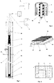
- the level meter shown in figure 1 comprises a delay line having two conductors 1 and 2 which are connected through one end to a pulse generator 3 and a reflectometer 4.
- the pulse generator supplies one pulse for each measurement cycle.
- the rise time of this pulse is very short; it takes less than 1 ns to rise to 90% of its maximum amplitude. Its duration is longer than the two-way propagation time of the wave in the delay line.
- the electronic device composed of the pulse generator and the reflectometer is well known in the RADAR field and will not be described in detail here.
- the main item of the level meter according to the invention is a delay line which guides the wave in both directions, thereby eliminating false echoes from obstacles outside the delay line.
- This delay line extends preferably along a linear path and perpendicularly to the level 21 of the liquid to be measured. According to a variant, it could be arranged at an angle other than 90° with respect to the liquid level.
- the lower end of this delay line is short-circuited by a metal disc 5 which is secured via a screw 6 to the two conductors 1 and 2.
- the delay line is a coaxial line.
- Its inner conductor 1 is a tube (as shown) or a solid rod made of steel and having a diameter of e.g. 10 mm.
- the inner conductor is held in the outer conductor 2 by means of a plurality of adjustable studs 7 made of an insulating material such as polytetrafluoroethylene and screwed in an angularly spaced relationship into the outer conductor 2. Only one such stud is shown.
- the inner conductor 1 is fixed to a metal cone 8 by which it is electrically connected to a cable 9, especially a coaxial cable.
- the other conductor of this cable 9 is connected to the outer conductor 2 of the delay line by at least one metallic sleeve 10.
- the outer conductor 2 presents a plurality of openings 11 through which the liquid can enter into the interspace between the inner and outer conductor 1, 2 of the delay line.
- the liquid is not an ideal dielectric medium the currents there-through would reduce considerably the signal amplitude P over the length of the delay line.
- the distributed capacitance of the delay line then includes both the (constant) dielectric of the layer 10 and that of the interspace which varies according to wether the liquid is present or not.
- Figure 2 shows an alternative realisation of the delay line. It differs from the coaxial line according to figure 1 by the fact that the inner conductor 13 is a spiral-shaped copper conductor which is protected by an insulating sheath 14. It is wound about a glass tube 15 located in the centre of the delay line.
- the outer conductor 2 with its openings 11 corresponds to that of figure 1. Due to the spiral shape of the inner conductor the propagation velocity of a wave along the axis is reduced and the time resolution of the analyzed signal is correspondingly improved.
- the conductor acting as "inner” conductor consists of a copper strip 16 which is wound about an insulating support 17 of flat rectangular cross-section. This support and the copper strip are sealed under a polytetrafluoroethylene layer 18 which has the same function as the layers 12 and 14.
- the other conductor 19 consists either of a metal sheet 19 extending linearly along the support 17 or of the electrically conductive wall of the recipient in which the liquid to be measured is contained. The distance between both conductors is ensured by distance pieces 20.
- the outer conductor 2 (figure 1 or 2) or the conductor 19 (figure 3) is at the same ground potential as the electronic device 3, 4.
- a pulse of very short rise time ( ⁇ 1 ns) is injected into the delay line. The duration of this pulse is chosen to exceed the propagation time to and fro between the generator 3 and the lowest level to be measured.
- a typical echo signal resulting from this pulse is shown in figure 4. It presents three significant steps: A first step A corresponds to the transition between the cable 9 and the delay line 1, 2 or 13, 2 or 16, 19.
- the second step B varies in time t according to the level 21 of the liquid, and the third step C is representative of the short-circuit of the delay line constituted by the disc 5 at the lower end thereof.
- the position in time of the step B is then analyzed in the reflectometer 4.
- the steps A and C can easily be discerned from step B since they appear at fixed and well-known instants after the emission of the pulse from the generator 3.
- the pulse frequency defining the cycle period depends on the processing speed of the reflectometer and can amount to 100 kHz or more. Therefore, the measurement can practically be considered as being continuous. Reflections of the pulse energy outside the delay line do practically not create echoes in the line and therefore do not disturb the analysis of the useful echoes in the reflectometer.
- the level of the liquid to be measured depends upon the time between transmission instant and the reception instant of the step B originated by the liquid level. This time can be related to the distance between the liquid level and a reference level using the wave propagation speed. Calibration of the level meter according to the invention can be made by comparison with other liquid measuring methods or by measuring levels which are known from volume calculations.
- the main advantage of the present invention over classical RADAR level meters consists in the fact that the level is allowed to be hidden behind obstacles such as cover lids, flanges etc. For this reason this meter is particularly adapted for use in closed recipients which are submitted in operation to high temperatures and/or pressures.
Landscapes
- Physics & Mathematics (AREA)
- Electromagnetism (AREA)
- Thermal Sciences (AREA)
- Fluid Mechanics (AREA)
- General Physics & Mathematics (AREA)
- Measurement Of Levels Of Liquids Or Fluent Solid Materials (AREA)
Priority Applications (1)
| Application Number | Priority Date | Filing Date | Title |
|---|---|---|---|
| EP98123514A EP1010970A1 (fr) | 1998-12-15 | 1998-12-15 | Capteur de niveau pour liquides diélectriques |
Applications Claiming Priority (1)
| Application Number | Priority Date | Filing Date | Title |
|---|---|---|---|
| EP98123514A EP1010970A1 (fr) | 1998-12-15 | 1998-12-15 | Capteur de niveau pour liquides diélectriques |
Publications (1)
| Publication Number | Publication Date |
|---|---|
| EP1010970A1 true EP1010970A1 (fr) | 2000-06-21 |
Family
ID=8233116
Family Applications (1)
| Application Number | Title | Priority Date | Filing Date |
|---|---|---|---|
| EP98123514A Withdrawn EP1010970A1 (fr) | 1998-12-15 | 1998-12-15 | Capteur de niveau pour liquides diélectriques |
Country Status (1)
| Country | Link |
|---|---|
| EP (1) | EP1010970A1 (fr) |
Cited By (3)
| Publication number | Priority date | Publication date | Assignee | Title |
|---|---|---|---|---|
| EP1956348A2 (fr) * | 2007-02-08 | 2008-08-13 | Krohne Messtechnik Gmbh & Co. Kg | Utilisation d'un appareil de mesure du niveau de remplissage fonctionnant selon le principe de radar |
| KR100970424B1 (ko) * | 2009-12-09 | 2010-07-15 | 두온 시스템 (주) | 프로브 접촉 방식의 레벨 측정 장치 |
| CN103608650A (zh) * | 2011-05-04 | 2014-02-26 | 雪佛龙美国公司 | 用于感测液位的系统和方法 |
Citations (5)
| Publication number | Priority date | Publication date | Assignee | Title |
|---|---|---|---|---|
| US3695107A (en) * | 1970-06-01 | 1972-10-03 | Hertz Carl H | Method of measuring the level of a material in a tank, and an apparatus for practicing this method |
| US3832900A (en) * | 1971-06-28 | 1974-09-03 | Sperry Rand Corp | Apparatus and method for measuring the level of a contained liquid |
| US3995212A (en) * | 1975-04-14 | 1976-11-30 | Sperry Rand Corporation | Apparatus and method for sensing a liquid with a single wire transmission line |
| EP0042186A1 (fr) * | 1980-06-13 | 1981-12-23 | Shell Internationale Researchmaatschappij B.V. | Méthode et appareil pour mesurer la position d'une interface entre des matériaux différents par réflectométrie reliée à la fréquence |
| US4924700A (en) * | 1987-12-16 | 1990-05-15 | Whessoe. S.A. | Apparatus for measuring storage parameters such as level and temperature of liquids or fluids of different densities in a tank |
-
1998
- 1998-12-15 EP EP98123514A patent/EP1010970A1/fr not_active Withdrawn
Patent Citations (5)
| Publication number | Priority date | Publication date | Assignee | Title |
|---|---|---|---|---|
| US3695107A (en) * | 1970-06-01 | 1972-10-03 | Hertz Carl H | Method of measuring the level of a material in a tank, and an apparatus for practicing this method |
| US3832900A (en) * | 1971-06-28 | 1974-09-03 | Sperry Rand Corp | Apparatus and method for measuring the level of a contained liquid |
| US3995212A (en) * | 1975-04-14 | 1976-11-30 | Sperry Rand Corporation | Apparatus and method for sensing a liquid with a single wire transmission line |
| EP0042186A1 (fr) * | 1980-06-13 | 1981-12-23 | Shell Internationale Researchmaatschappij B.V. | Méthode et appareil pour mesurer la position d'une interface entre des matériaux différents par réflectométrie reliée à la fréquence |
| US4924700A (en) * | 1987-12-16 | 1990-05-15 | Whessoe. S.A. | Apparatus for measuring storage parameters such as level and temperature of liquids or fluids of different densities in a tank |
Cited By (3)
| Publication number | Priority date | Publication date | Assignee | Title |
|---|---|---|---|---|
| EP1956348A2 (fr) * | 2007-02-08 | 2008-08-13 | Krohne Messtechnik Gmbh & Co. Kg | Utilisation d'un appareil de mesure du niveau de remplissage fonctionnant selon le principe de radar |
| KR100970424B1 (ko) * | 2009-12-09 | 2010-07-15 | 두온 시스템 (주) | 프로브 접촉 방식의 레벨 측정 장치 |
| CN103608650A (zh) * | 2011-05-04 | 2014-02-26 | 雪佛龙美国公司 | 用于感测液位的系统和方法 |
Similar Documents
| Publication | Publication Date | Title |
|---|---|---|
| US5656774A (en) | Apparatus and method for sensing fluid level | |
| KR100422773B1 (ko) | 스위프거리게이트를구비하는임펄스레이더 | |
| US4905008A (en) | Radar type underground searching apparatus | |
| Thorne et al. | Measuring suspended sediment concentrations using acoustic backscatter devices | |
| US4335613A (en) | Apparatus for indicating the freezing of the surface of an asphalt road, paved runway, or the like | |
| AU780044B2 (en) | Radar apparatus for imaging and/or spectrometric analysis and methods of performing imaging and/or spectrometric analysis of a substance for dimensional measurement, identification and precision radar mapping | |
| US6724197B2 (en) | Fill-level detector | |
| US9360361B2 (en) | System and method for emulsion measurement and profiling | |
| US10184820B2 (en) | Guided wave radar level gauge system for interface measurement | |
| US20070090992A1 (en) | Radar level gauge system and transmission line probe for use in such a system | |
| CA2314213C (fr) | Dispositif de mesure du niveau de materiau dans un recipient | |
| US6662648B2 (en) | Filling level measuring device | |
| JP3220124B2 (ja) | 充填レベル測定装置 | |
| EP0741291B1 (fr) | Appareil de mesure | |
| JP2004519661A (ja) | 材料のリミットレベルの捕捉検出方法およびこのための装置 | |
| EP1010970A1 (fr) | Capteur de niveau pour liquides diélectriques | |
| US4158168A (en) | Acoustic waveguides for sensing and locating corona discharges | |
| Andrieu et al. | Land mine detection with an ultra-wideband SAR system | |
| NO158157B (no) | Fremgangsmaate og apparat til paavisning av en koronautladningskilde i et elektrisk apparat. | |
| US20020010546A1 (en) | Apparatus and method for determining the propagation velocity of an electromagnetic signal in a subsurface medium utilizing ground penetrating radar | |
| Farid et al. | Perspectives of Water Level Measurement in Plastic Pipes Using Wideband Horn Antenna. | |
| AU2015306065A1 (en) | Method and apparatus for detecting the level of a medium | |
| Duflos et al. | Time-frequency analysis of ground penetrating radar signals for mines detection applications | |
| Inomata et al. | 2-dimensional measuring method using a wide-area surveillance sensor with leaky coaxial cables | |
| KR830005569A (ko) | 초음파 검출장치 |
Legal Events
| Date | Code | Title | Description |
|---|---|---|---|
| PUAI | Public reference made under article 153(3) epc to a published international application that has entered the european phase |
Free format text: ORIGINAL CODE: 0009012 |
|
| AK | Designated contracting states |
Kind code of ref document: A1 Designated state(s): AT BE CH CY DE DK ES FI FR GB GR IE IT LI LU MC NL PT SE |
|
| AX | Request for extension of the european patent |
Free format text: AL;LT;LV;MK;RO;SI |
|
| AKX | Designation fees paid | ||
| STAA | Information on the status of an ep patent application or granted ep patent |
Free format text: STATUS: THE APPLICATION IS DEEMED TO BE WITHDRAWN |
|
| 18D | Application deemed to be withdrawn |
Effective date: 20001222 |
|
| REG | Reference to a national code |
Ref country code: DE Ref legal event code: 8566 |