EP1010991A2 - Torsonde - Google Patents
Torsonde Download PDFInfo
- Publication number
- EP1010991A2 EP1010991A2 EP99122594A EP99122594A EP1010991A2 EP 1010991 A2 EP1010991 A2 EP 1010991A2 EP 99122594 A EP99122594 A EP 99122594A EP 99122594 A EP99122594 A EP 99122594A EP 1010991 A2 EP1010991 A2 EP 1010991A2
- Authority
- EP
- European Patent Office
- Prior art keywords
- torsonde
- metal structure
- elements
- metal
- transmitter
- Prior art date
- Legal status (The legal status is an assumption and is not a legal conclusion. Google has not performed a legal analysis and makes no representation as to the accuracy of the status listed.)
- Granted
Links
- 229910052751 metal Inorganic materials 0.000 claims abstract description 38
- 239000002184 metal Substances 0.000 claims abstract description 38
- 239000000523 sample Substances 0.000 claims description 20
- 229910052782 aluminium Inorganic materials 0.000 claims description 4
- XAGFODPZIPBFFR-UHFFFAOYSA-N aluminium Chemical compound [Al] XAGFODPZIPBFFR-UHFFFAOYSA-N 0.000 claims description 4
- 230000006698 induction Effects 0.000 claims description 4
- 230000008878 coupling Effects 0.000 abstract 1
- 238000010168 coupling process Methods 0.000 abstract 1
- 238000005859 coupling reaction Methods 0.000 abstract 1
- 238000010276 construction Methods 0.000 description 17
- 230000001681 protective effect Effects 0.000 description 5
- 230000005540 biological transmission Effects 0.000 description 4
- 230000000694 effects Effects 0.000 description 4
- 238000001514 detection method Methods 0.000 description 3
- 238000004519 manufacturing process Methods 0.000 description 3
- XEEYBQQBJWHFJM-UHFFFAOYSA-N Iron Chemical compound [Fe] XEEYBQQBJWHFJM-UHFFFAOYSA-N 0.000 description 2
- 239000000463 material Substances 0.000 description 2
- 238000005259 measurement Methods 0.000 description 2
- 238000013016 damping Methods 0.000 description 1
- 238000009413 insulation Methods 0.000 description 1
- 229910052742 iron Inorganic materials 0.000 description 1
- 238000000034 method Methods 0.000 description 1
- 230000002441 reversible effect Effects 0.000 description 1
- 239000007787 solid Substances 0.000 description 1
- 238000004804 winding Methods 0.000 description 1
- 239000002023 wood Substances 0.000 description 1
Images




Classifications
-
- G—PHYSICS
- G01—MEASURING; TESTING
- G01V—GEOPHYSICS; GRAVITATIONAL MEASUREMENTS; DETECTING MASSES OR OBJECTS; TAGS
- G01V3/00—Electric or magnetic prospecting or detecting; Measuring magnetic field characteristics of the earth, e.g. declination, deviation
- G01V3/08—Electric or magnetic prospecting or detecting; Measuring magnetic field characteristics of the earth, e.g. declination, deviation operating with magnetic or electric fields produced or modified by objects or geological structures or by detecting devices
- G01V3/081—Electric or magnetic prospecting or detecting; Measuring magnetic field characteristics of the earth, e.g. declination, deviation operating with magnetic or electric fields produced or modified by objects or geological structures or by detecting devices the magnetic field is produced by the objects or geological structures
Definitions
- the invention relates to a door probe with at least one Transmitter that generates a magnetic field, and at least a receiver, the presence of metallic objects detectable by a change in the magnetic field is.
- the device disclosed there relates to the detection of a article provided with an electronic security element in a surveillance zone, for example in the exit area of a department store.
- the detection coils are also in here a so-called. Gate arranged what the above described Cost disadvantages and the difficulties in manufacturing of the device.
- the invention is therefore based on the object of eliminating the disadvantages mentioned; in particular, a cost-effective, easy-to-use system is to be made available, which can be produced using uniform manufacturing techniques.
- the transmitter and / or the receiver as essentially self-supporting metal construction is / are.
- This is the function of the transmitting or receiving coils as well as the support frame or protective covers in integrated form realized.
- the metal construction offers the required send and receive functions and can at the same time the necessary mechanical stability Apply as a gate probe without any additional superstructures.
- the metal construction can be dismantled. Due to this fact, the delivery and the delivery of the gate probe according to the invention considerably facilitated. Furthermore, the dismantling lowers and that this resulted in a reduced pack size for storage costs. Because of the dismantling, it is also conceivable that the Gate probe is used in changing locations; especially in today's time it is with the most diverse Events increasingly required, strict security precautions, for example against crime and terrorism.
- a toroid is put on. With such a toroid which has a winding becomes the metal construction sent.
- the received signal can also can be removed via the toroid on the metal construction.
- a single toroidal core can be provided, which both the transmit function and, via the change in impedance of the frame that conveys the reception function. You can also transmit and use multiple ring cores Receive functions are separated from each other.
- the metal construction preferably has individual tubular elements on. So that a stable and fast construction of the Metal construction possible. Furthermore, metal pipes are inexpensive and in practically any version on the Market available. There are round tubes, square tubes or also any other metal profiles to bring about the Advantages of the invention can be used.
- the metal construction preferably has individual mechanical ones Fasteners. So that the frame forming elements, such as the pipe elements, in more reliable Way to be connected. It will be a modular and thus variable structure of the door probe enables.
- the connecting elements are electrically conductive. Because of this, the Fasteners in addition to the mechanical connection at the same time the electrical connection of the construction elements, so that the required transmission or reception inductance is made available.
- the tubular elements are preferably end-to-end with connecting pieces provided, via which they with the connecting elements are connected.
- These connectors which for example are made of solid aluminum material the ability to match the pipes to the shape of the fasteners adapt.
- connection pieces is particularly advantageous if this has a screw clamp with the connecting elements are connected.
- the Connectors in holes that are in the connectors are provided, and a screw is inserted perpendicular to the hole axis for jamming the connecting pieces screwed into the corresponding connecting element.
- the connecting pieces preferably have a countersink for twist-proof screw clamping.
- the Connectors have a groove in which the Screw clamp engages. If this groove than around the cylindrical Connector circumferential groove is formed, so This facilitates the assembly of the gate probe, since the tube in arbitrarily rotated position in the connecting element fixable is. Securing the pipe against accidental Slipping out of the connecting element as well as the exact positioning is also guaranteed by the groove.
- the impedance of the metal structure is preferred provided inductance by in the vicinity of the Metal structure changeable existing metal objects.
- the receiver and transmitter are symmetrical are built up. Such a symmetrical structure can be realized by the reversibility of the system. In other words, the transmitter can also be used as Receiver work and vice versa.
- the induction changes of the transmitter and of the Receiver can be evaluated, and you thus have two signals Available. As a result, the measurement accuracy is improved.
- the metal construction is preferably made of aluminum. In order to it has sufficient conductivity; further is aluminum as a light metal for transport as well as for Structure of the construction advantageous.
- the ring core (s) is / are preferably sinusoidal or pulse-shaped excitable. Both of these known detection methods can be used advantageously in the context of the invention.
- the metal construction has the configuration of an "eight".
- Such Arrangement has a compensating effect because of the amplitudes the interference signals then have the opposite effect are and largely cancel each other out in this way.
- the metal construction can preferably be plastic pipe elements exhibit. This is useful if, for example insulation between the transmitter and receiver side is desired.
- the invention is based on the surprising finding that by forming a gate probe as a self-supporting Metal structure an inexpensive and practical Customized, extremely effective solution is provided. There are no disadvantages of a complex Support and protection structure for the transmission or Receiving coils. Due to the advantageous dismantling and the construction by means of pipes and connecting elements is guaranteed modular system available, which is variable and everywhere can be used.
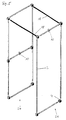
- Fig. 1 shows the construction of a door probe, which consists of tubular elements 2 is composed.
- the pipe elements 2 are over To connect connecting elements 4 together. End have the pipe elements 2 connectors 6, on which they are connected to the connecting elements 4 can.
- the connecting elements 4 cylindrical holes 8 are provided.
- One of the pipe elements 2 carries a toroidal core 10 made of iron to end the frame.
- the door probe according to the invention work according to the damping principle.
- the toroidal core 10 is a component of an oscillator circuit, which in the from Pipe elements 2 existing pipe system induces a current.
- the metallic frame acts as an inductor whose Impedance through metal objects through the frame led, changed. The resulting change in amplitude can be recorded as a signal value and for example be converted to an alarm tone.
- Fig. 2 shows an exploded view of a connecting element 4 and the ends of two tubular elements 2 with corresponding Connectors 6.
- the connector 4 has four bores 8, 12. Two of the holes 8, which designed in the present example as the larger holes 8 are used to accommodate the connectors 6 the tubular elements 2.
- the smaller holes 12 are with provided with an internal thread and for receiving screws 14 designed. Now becomes a pipe element 2 with its connector 6 in the corresponding bore 8 of the connecting element 4 introduced, the tubular element 2 or the connector 6 from the side through the clamping Effect of the corresponding screw 14 can be set. This is for the stated purpose in the corresponding Drilled hole 12. Run in the example the tips of the screws 14 at an angle of approximately 90 ° conical out.
- FIG. 4 is a third embodiment of the invention illustrated.
- the metallic pipe elements 2 and the connecting elements 4 arranged so that the compensating Configuration of an "eight" is realized.
- a toroid can also be used in this embodiment suitable location of a pipe element 2 of the pipe system be placed. Even with this special arrangement the same connecting elements 4 can be used as in the other Embodiments of the invention.
- FIG. 5 A fourth embodiment of the invention is in FIG. 5 shown. Again, two sides 24, 26 are the gate probe electrically isolated from each other by plastic tubes 18. On the metallic tubular elements 2 are ring cores 10 for each side 24, 26 of the gate probe is arranged. It is of course, any similar arrangement of toroidal cores 10, which is generally simply over the tubular elements 2 can be pushed, conceivable.
- FIG. 6 shows a further variant of the arrangement of tubular elements 2, connecting elements 4, plastic tube elements 18 and a ring core 10.
- the ring core 10 is over here a tubular element 2 is pushed in the head part of the door probe.
- FIG. 7 A sixth embodiment of the present invention is shown in Fig. 7.
- the gate probe is through again Plastic tubes 18 divided into two sides 28, 30.
- the Right side 30 of the door probe is through again shorter plastic pipes 32 in two insulated from each other Sections 34, 36 divided.
- Each of sections 28, 34, 36 each carries a ring core 10.
- the present arrangement is preferably operated so that the section 28 is used as a transmitter, while sections 34 and 36 can be interconnected for reception in opposite phases. To this The transmission signal can be compensated in this way.
- This too Arrangement is in terms of the send and receive characteristics reversible.
Landscapes
- Remote Sensing (AREA)
- Engineering & Computer Science (AREA)
- Life Sciences & Earth Sciences (AREA)
- Physics & Mathematics (AREA)
- Geology (AREA)
- Environmental & Geological Engineering (AREA)
- Electromagnetism (AREA)
- General Life Sciences & Earth Sciences (AREA)
- General Physics & Mathematics (AREA)
- Geophysics (AREA)
- Geophysics And Detection Of Objects (AREA)
- Transition And Organic Metals Composition Catalysts For Addition Polymerization (AREA)
- Prostheses (AREA)
- Materials For Medical Uses (AREA)
Abstract
Description
- Fig. 1
- eine Explosionsdarstellung einer ersten Ausführungsform der vorliegenden Erfindung;
- Fig. 2
- eine Explosionsdarstellung zur Erläuterung der Funktion eines Verbindungselementes;
- Fig. 3
- eine Explosionsdarstellung einer zweiten Ausführungsform der Erfindung;
- Fig. 4
- eine Explosionsdarstellung einer dritten Ausführungsform der Erfindung;
- Fig. 5
- eine Explosionsdarstellung einer vierten Ausführungsform der Erfindung;
- Fig. 6
- eine Explosionsdarstellung einer fünften Ausführungsform der Erfindung; und
- Fig. 7
- eine Explosionsdarstellung einer sechsten Ausführungsform der Erfindung.
Claims (15)
- Torsonde mitmindestens einem Sender, welcher ein Magnetfeld erzeugt,und mindestens einem Empfänger,wobei die Anwesenheit metallischer Gegenstände über eine Veränderung des Magnetfeldes nachweisbar ist,
dadurch gekennzeichnet,daß der Sender und/oder der Empfänger als im wesentlichen selbsttragende Metallkonstruktion (2, 4, 6, 8) ausgebildet ist/sind. - Torsonde nach Anspruch 1,
dadurch gekennzeichnet,
daß die Metallkonstruktion (2, 4, 6, 8) zerlegbar ist und einzelne Rohrelemente (2) aufweist. - Torsonde nach Anspruch 1 oder 2,
dadurch gekennzeichnet,
daß auf die Metallkonstruktion (2, 4, 6, 8) mindestens ein Ringkern (10) aufgesetzt ist. - Torsonde nach einem der Ansprüche 1 bis 3,
dadurch gekennzeichnet,
daß die Metallkonstruktion (2, 4, 6, 8) einzelne elektrisch leitfähige, mechanische Verbindungselemente (4) aufweist. - Torsonde nach Anspruch 4,
dadurch gekennzeichnet,
daß die Rohrelemente (2) endseitig mit Verbindungsstücken (6) versehen sind, über welche sie mit den Verbindungselementen (4) über eine Schraubklemmung (12, 14) verbunden sind. - Torsonde nach Anspruch 5,
dadurch gekennzeichnet,
daß die Verbindungsstücke (6) eine Senkung (16) zur verdrehsicheren Schraubklemmung aufweisen. - Torsonde nach einem der Ansprüche 5 oder 6,
dadurch gekennzeichnet,
daß die Verbindungsstücke (6) eine Nut aufweisen, in welche die Schraubklemmung eingreift. - Torsonde nach einem der vorhergehenden Ansprüche,
dadurch gekennzeichnet,
daß die Impedanz der durch die Metallkonstruktion (2, 4, 6, 8) bereitgestellten Induktivität durch in der Umgebung der Metallkonstruktion (2, 4, 6, 8) vorhandene Metallobjekte veränderbar ist. - Torsonde nach einem der vorhergehenden Ansprüche,
dadurch gekennzeichnet,
daß Empfänger und Sender symmetrisch aufgebaut sind. - Torsonde nach einem der vorhergehenden Ansprüche,
dadurch gekennzeichnet,
daß die Induktionsänderungen des Senders und des Empfängers auswertbar sind, wobei zur Verarbeitung der aus den Induktionsänderungen resultierenden Signale eine Differenzstufe vorgesehen ist. - Torsonde nach einem der vorhergehenden Ansprüche,
dadurch gekennzeichnet,
daß die Metallkonstruktion (2, 4, 6, 8) aus Aluminium besteht. - Torsonde nach einem der Ansprüche 3 bis 11,
dadurch gekennzeichnet,
daß der/die Ringkern(e) sinusförmig erregbar ist/sind. - Torsonde nach einem der Ansprüche 3 bis 11,
dadurch gekennzeichnet,
daß der/die Ringkern(e) pulsförmig erregbar ist/sind. - Torsonde nach einem der vorhergehenden Ansprüche,
dadurch gekennzeichnet,
daß die Metallkonstruktion (2, 4, 6, 8) die Konfiguration einer "Acht" aufweist. - Torsonde nach einem der vorhergehenden Ansprüche,
dadurch gekennzeichnet,
daß die Metallkonstruktion (2, 4, 6, 8) Kunststoffrohrelemente (18, 32) aufweist.
Applications Claiming Priority (2)
| Application Number | Priority Date | Filing Date | Title |
|---|---|---|---|
| DE19858714 | 1998-12-18 | ||
| DE19858714A DE19858714A1 (de) | 1998-12-18 | 1998-12-18 | Torsonde |
Publications (3)
| Publication Number | Publication Date |
|---|---|
| EP1010991A2 true EP1010991A2 (de) | 2000-06-21 |
| EP1010991A3 EP1010991A3 (de) | 2003-03-19 |
| EP1010991B1 EP1010991B1 (de) | 2006-09-27 |
Family
ID=7891732
Family Applications (1)
| Application Number | Title | Priority Date | Filing Date |
|---|---|---|---|
| EP99122594A Expired - Lifetime EP1010991B1 (de) | 1998-12-18 | 1999-11-12 | Torsonde |
Country Status (4)
| Country | Link |
|---|---|
| EP (1) | EP1010991B1 (de) |
| AT (1) | ATE341008T1 (de) |
| DE (2) | DE19858714A1 (de) |
| ES (1) | ES2272032T3 (de) |
Families Citing this family (1)
| Publication number | Priority date | Publication date | Assignee | Title |
|---|---|---|---|---|
| US9424724B2 (en) | 2013-08-02 | 2016-08-23 | Bibliotheca Rfid Library Systems Ag | Single turn magnetic drive loop for electronic article surveillance |
Citations (2)
| Publication number | Priority date | Publication date | Assignee | Title |
|---|---|---|---|---|
| US4605898A (en) | 1981-11-06 | 1986-08-12 | Outokumpu Oy | Pulse field metal detector with spaced, dual coil transmitter and receiver systems |
| DE19503896A1 (de) | 1995-02-07 | 1996-08-08 | Esselte Meto Int Gmbh | Einrichtung zur Detektierung eines mit einem elektronischen Sicherungselement versehenen Artikels |
Family Cites Families (6)
| Publication number | Priority date | Publication date | Assignee | Title |
|---|---|---|---|---|
| US605898A (en) * | 1898-06-21 | Composition of matter for plastering | ||
| DE1623104B2 (de) * | 1967-06-23 | 1974-09-12 | Clamann & Grahnert, X 8016 Dresden | Spulensystem für Metallspürgerät |
| US4016553A (en) * | 1975-06-27 | 1977-04-05 | Knogo Corporation | Article detection system with near field electromagnetic wave control |
| FR2553523B1 (fr) * | 1983-10-17 | 1986-06-13 | Raibaud Guy | Alarme inductive de protection contre le vol par detection de circuits resonnants |
| FR2619454B1 (fr) * | 1987-08-14 | 1990-06-29 | Automatisme Tech Avancees | Procedes et portiques ou sas pour detecter le passage de masses metalliques |
| DE29822602U1 (de) * | 1998-12-18 | 1999-02-18 | Fa. Ing. Klaus Ebinger, 51149 Köln | Torsonde |
-
1998
- 1998-12-18 DE DE19858714A patent/DE19858714A1/de not_active Withdrawn
-
1999
- 1999-11-12 ES ES99122594T patent/ES2272032T3/es not_active Expired - Lifetime
- 1999-11-12 DE DE59913878T patent/DE59913878D1/de not_active Expired - Fee Related
- 1999-11-12 AT AT99122594T patent/ATE341008T1/de not_active IP Right Cessation
- 1999-11-12 EP EP99122594A patent/EP1010991B1/de not_active Expired - Lifetime
Patent Citations (2)
| Publication number | Priority date | Publication date | Assignee | Title |
|---|---|---|---|---|
| US4605898A (en) | 1981-11-06 | 1986-08-12 | Outokumpu Oy | Pulse field metal detector with spaced, dual coil transmitter and receiver systems |
| DE19503896A1 (de) | 1995-02-07 | 1996-08-08 | Esselte Meto Int Gmbh | Einrichtung zur Detektierung eines mit einem elektronischen Sicherungselement versehenen Artikels |
Also Published As
| Publication number | Publication date |
|---|---|
| DE59913878D1 (de) | 2006-11-09 |
| ATE341008T1 (de) | 2006-10-15 |
| EP1010991A3 (de) | 2003-03-19 |
| DE19858714A1 (de) | 2000-06-21 |
| EP1010991B1 (de) | 2006-09-27 |
| ES2272032T3 (es) | 2007-04-16 |
Similar Documents
| Publication | Publication Date | Title |
|---|---|---|
| DE68918549T2 (de) | Verschiebungsmessapparat. | |
| EP2594714B1 (de) | Vorrichtung zur kontaktlosen Übertragung von elektrischer Energie zwischen einer Wand und einem an dieser Wand befestigten Flügel | |
| DE1648358A1 (de) | Verfahren und Geraet zur Bestimmung von Unstetigkeitsstellen in elektrisch leitenden Materialien | |
| DE102015115264B3 (de) | Zentrierhalteeinrichtung für eine Rogowski-Spule, Messeinrichtung, Leistungselektronikeinrichtung und ein Verfahren zur Anordnung einer Rogowski-Spule | |
| WO2001036903A1 (de) | Messseil-wegsensor | |
| EP2149784B1 (de) | Magnetisches Wegsensorsystem | |
| DE10234960B4 (de) | Sensor nach dem Laufzeitprinzip mit einer Detektoreinheit für mechanisch-elastische Wellen | |
| DE2758969C2 (de) | Kreiszylindrisches Gehäuse für ein Schaltgerät | |
| DE68911449T2 (de) | Stromsensor mit einem Element aus amorphem magnetischem Metall. | |
| EP1010991B1 (de) | Torsonde | |
| DE3032319A1 (de) | Induktiver koppler | |
| DE3331462C2 (de) | ||
| DE2942847A1 (de) | Magnetfelddifferenzsonde | |
| DE4013429C2 (de) | Spannungsdetektor | |
| DE29822602U1 (de) | Torsonde | |
| EP0767390B1 (de) | Suchgerät zum Absuchen grosser Flächen | |
| DE10258115B4 (de) | Breitbandiges Messmodul zur Strommessung an Einrichtungen der Leistungselektronik | |
| EP0936741B1 (de) | Induktiver Näherungsschalter mit einem vorzugsweise aus einem Stück bestehenden Gehäuse | |
| DE2506248C3 (de) | Wirbelstromprüfgerät für die zerstörungsfreie Prüfung von Gegenständen | |
| EP0957377A2 (de) | Vorrichtung und Verfahren zum Orten von Metallteilen | |
| DE19516235C2 (de) | Verbindungsanordnung | |
| DE102015212120A1 (de) | Sensoreinrichtung zum Detektieren eines sich entlang einer Fahrschiene bewegenden Rades | |
| DE69126427T2 (de) | Leitungskupplungstransformator | |
| DE2228088C2 (de) | Klemme zum Verbinden von wenigstens zwei Rund- oder Sektorleitern mit einem AnschraBbolzen eines Transformators | |
| EP1010990B1 (de) | Anordnung zum Erzeugen und/oder Empfangen eines Magnetfeldes |
Legal Events
| Date | Code | Title | Description |
|---|---|---|---|
| PUAI | Public reference made under article 153(3) epc to a published international application that has entered the european phase |
Free format text: ORIGINAL CODE: 0009012 |
|
| AK | Designated contracting states |
Kind code of ref document: A2 Designated state(s): AT BE CH CY DE DK ES FI FR GB GR IE IT LI LU MC NL PT SE |
|
| AX | Request for extension of the european patent |
Free format text: AL;LT;LV;MK;RO;SI |
|
| PUAL | Search report despatched |
Free format text: ORIGINAL CODE: 0009013 |
|
| AK | Designated contracting states |
Kind code of ref document: A3 Designated state(s): AT BE CH CY DE DK ES FI FR GB GR IE IT LI LU MC NL PT SE |
|
| AX | Request for extension of the european patent |
Extension state: AL LT LV MK RO SI |
|
| 17P | Request for examination filed |
Effective date: 20030519 |
|
| AKX | Designation fees paid |
Designated state(s): AT BE CH CY DE DK ES FI FR GB GR IE IT LI LU MC NL PT SE |
|
| GRAP | Despatch of communication of intention to grant a patent |
Free format text: ORIGINAL CODE: EPIDOSNIGR1 |
|
| GRAS | Grant fee paid |
Free format text: ORIGINAL CODE: EPIDOSNIGR3 |
|
| GRAA | (expected) grant |
Free format text: ORIGINAL CODE: 0009210 |
|
| AK | Designated contracting states |
Kind code of ref document: B1 Designated state(s): AT BE CH CY DE DK ES FI FR GB GR IE IT LI LU MC NL PT SE |
|
| PG25 | Lapsed in a contracting state [announced via postgrant information from national office to epo] |
Ref country code: NL Free format text: LAPSE BECAUSE OF FAILURE TO SUBMIT A TRANSLATION OF THE DESCRIPTION OR TO PAY THE FEE WITHIN THE PRESCRIBED TIME-LIMIT Effective date: 20060927 Ref country code: IT Free format text: LAPSE BECAUSE OF FAILURE TO SUBMIT A TRANSLATION OF THE DESCRIPTION OR TO PAY THE FEE WITHIN THE PRE;WARNING: LAPSES OF ITALIAN PATENTS WITH EFFECTIVE DATE BEFORE 2007 MAY HAVE OCCURRED AT ANY TIME BEFORE 2007. THE CORRECT EFFECTIVE DATE MAY BE DIFFERENT FROM THE ONE RECORDED.SCRIBED TIME-LIMIT Effective date: 20060927 Ref country code: IE Free format text: LAPSE BECAUSE OF FAILURE TO SUBMIT A TRANSLATION OF THE DESCRIPTION OR TO PAY THE FEE WITHIN THE PRESCRIBED TIME-LIMIT Effective date: 20060927 Ref country code: FI Free format text: LAPSE BECAUSE OF FAILURE TO SUBMIT A TRANSLATION OF THE DESCRIPTION OR TO PAY THE FEE WITHIN THE PRESCRIBED TIME-LIMIT Effective date: 20060927 |
|
| REG | Reference to a national code |
Ref country code: GB Ref legal event code: FG4D Free format text: NOT ENGLISH |
|
| REG | Reference to a national code |
Ref country code: CH Ref legal event code: EP |
|
| REG | Reference to a national code |
Ref country code: IE Ref legal event code: FG4D Free format text: LANGUAGE OF EP DOCUMENT: GERMAN |
|
| REF | Corresponds to: |
Ref document number: 59913878 Country of ref document: DE Date of ref document: 20061109 Kind code of ref document: P |
|
| PG25 | Lapsed in a contracting state [announced via postgrant information from national office to epo] |
Ref country code: MC Free format text: LAPSE BECAUSE OF NON-PAYMENT OF DUE FEES Effective date: 20061130 Ref country code: LI Free format text: LAPSE BECAUSE OF NON-PAYMENT OF DUE FEES Effective date: 20061130 Ref country code: CH Free format text: LAPSE BECAUSE OF NON-PAYMENT OF DUE FEES Effective date: 20061130 Ref country code: BE Free format text: LAPSE BECAUSE OF NON-PAYMENT OF DUE FEES Effective date: 20061130 |
|
| GBT | Gb: translation of ep patent filed (gb section 77(6)(a)/1977) |
Effective date: 20061127 |
|
| PG25 | Lapsed in a contracting state [announced via postgrant information from national office to epo] |
Ref country code: SE Free format text: LAPSE BECAUSE OF FAILURE TO SUBMIT A TRANSLATION OF THE DESCRIPTION OR TO PAY THE FEE WITHIN THE PRESCRIBED TIME-LIMIT Effective date: 20061227 Ref country code: DK Free format text: LAPSE BECAUSE OF FAILURE TO SUBMIT A TRANSLATION OF THE DESCRIPTION OR TO PAY THE FEE WITHIN THE PRESCRIBED TIME-LIMIT Effective date: 20061227 |
|
| NLV1 | Nl: lapsed or annulled due to failure to fulfill the requirements of art. 29p and 29m of the patents act | ||
| PG25 | Lapsed in a contracting state [announced via postgrant information from national office to epo] |
Ref country code: PT Free format text: LAPSE BECAUSE OF FAILURE TO SUBMIT A TRANSLATION OF THE DESCRIPTION OR TO PAY THE FEE WITHIN THE PRESCRIBED TIME-LIMIT Effective date: 20070313 |
|
| ET | Fr: translation filed | ||
| REG | Reference to a national code |
Ref country code: ES Ref legal event code: FG2A Ref document number: 2272032 Country of ref document: ES Kind code of ref document: T3 |
|
| REG | Reference to a national code |
Ref country code: IE Ref legal event code: FD4D |
|
| REG | Reference to a national code |
Ref country code: CH Ref legal event code: PL |
|
| PLBE | No opposition filed within time limit |
Free format text: ORIGINAL CODE: 0009261 |
|
| STAA | Information on the status of an ep patent application or granted ep patent |
Free format text: STATUS: NO OPPOSITION FILED WITHIN TIME LIMIT |
|
| 26N | No opposition filed |
Effective date: 20070628 |
|
| BERE | Be: lapsed |
Owner name: EBINGER, KLAUS Effective date: 20061130 |
|
| PG25 | Lapsed in a contracting state [announced via postgrant information from national office to epo] |
Ref country code: GR Free format text: LAPSE BECAUSE OF FAILURE TO SUBMIT A TRANSLATION OF THE DESCRIPTION OR TO PAY THE FEE WITHIN THE PRESCRIBED TIME-LIMIT Effective date: 20061228 |
|
| PG25 | Lapsed in a contracting state [announced via postgrant information from national office to epo] |
Ref country code: LU Free format text: LAPSE BECAUSE OF NON-PAYMENT OF DUE FEES Effective date: 20061112 |
|
| PG25 | Lapsed in a contracting state [announced via postgrant information from national office to epo] |
Ref country code: CY Free format text: LAPSE BECAUSE OF FAILURE TO SUBMIT A TRANSLATION OF THE DESCRIPTION OR TO PAY THE FEE WITHIN THE PRESCRIBED TIME-LIMIT Effective date: 20060927 |
|
| PGFP | Annual fee paid to national office [announced via postgrant information from national office to epo] |
Ref country code: DE Payment date: 20081126 Year of fee payment: 10 |
|
| PGFP | Annual fee paid to national office [announced via postgrant information from national office to epo] |
Ref country code: ES Payment date: 20081117 Year of fee payment: 10 Ref country code: AT Payment date: 20081124 Year of fee payment: 10 |
|
| PGFP | Annual fee paid to national office [announced via postgrant information from national office to epo] |
Ref country code: IT Payment date: 20081120 Year of fee payment: 10 |
|
| PGFP | Annual fee paid to national office [announced via postgrant information from national office to epo] |
Ref country code: FR Payment date: 20081030 Year of fee payment: 10 |
|
| PGFP | Annual fee paid to national office [announced via postgrant information from national office to epo] |
Ref country code: GB Payment date: 20081003 Year of fee payment: 10 |
|
| GBPC | Gb: european patent ceased through non-payment of renewal fee |
Effective date: 20091112 |
|
| REG | Reference to a national code |
Ref country code: FR Ref legal event code: ST Effective date: 20100730 |
|
| PG25 | Lapsed in a contracting state [announced via postgrant information from national office to epo] |
Ref country code: AT Free format text: LAPSE BECAUSE OF NON-PAYMENT OF DUE FEES Effective date: 20091112 |
|
| PG25 | Lapsed in a contracting state [announced via postgrant information from national office to epo] |
Ref country code: FR Free format text: LAPSE BECAUSE OF NON-PAYMENT OF DUE FEES Effective date: 20091130 |
|
| PG25 | Lapsed in a contracting state [announced via postgrant information from national office to epo] |
Ref country code: DE Free format text: LAPSE BECAUSE OF NON-PAYMENT OF DUE FEES Effective date: 20100601 |
|
| PG25 | Lapsed in a contracting state [announced via postgrant information from national office to epo] |
Ref country code: GB Free format text: LAPSE BECAUSE OF NON-PAYMENT OF DUE FEES Effective date: 20091112 |
|
| REG | Reference to a national code |
Ref country code: ES Ref legal event code: FD2A Effective date: 20110303 |
|
| PG25 | Lapsed in a contracting state [announced via postgrant information from national office to epo] |
Ref country code: IT Free format text: LAPSE BECAUSE OF NON-PAYMENT OF DUE FEES Effective date: 20091112 |
|
| PG25 | Lapsed in a contracting state [announced via postgrant information from national office to epo] |
Ref country code: ES Free format text: LAPSE BECAUSE OF NON-PAYMENT OF DUE FEES Effective date: 20110302 |
|
| PG25 | Lapsed in a contracting state [announced via postgrant information from national office to epo] |
Ref country code: ES Free format text: LAPSE BECAUSE OF NON-PAYMENT OF DUE FEES Effective date: 20091113 |