EP1011174A2 - Abgedichteter Steckverbinder und Verfahren zu dessen Herstellung - Google Patents
Abgedichteter Steckverbinder und Verfahren zu dessen Herstellung Download PDFInfo
- Publication number
- EP1011174A2 EP1011174A2 EP99118408A EP99118408A EP1011174A2 EP 1011174 A2 EP1011174 A2 EP 1011174A2 EP 99118408 A EP99118408 A EP 99118408A EP 99118408 A EP99118408 A EP 99118408A EP 1011174 A2 EP1011174 A2 EP 1011174A2
- Authority
- EP
- European Patent Office
- Prior art keywords
- metal collar
- insulating body
- cast resin
- connection area
- connector
- Prior art date
- Legal status (The legal status is an assumption and is not a legal conclusion. Google has not performed a legal analysis and makes no representation as to the accuracy of the status listed.)
- Withdrawn
Links
Images
Classifications
-
- H—ELECTRICITY
- H01—ELECTRIC ELEMENTS
- H01R—ELECTRICALLY-CONDUCTIVE CONNECTIONS; STRUCTURAL ASSOCIATIONS OF A PLURALITY OF MUTUALLY-INSULATED ELECTRICAL CONNECTING ELEMENTS; COUPLING DEVICES; CURRENT COLLECTORS
- H01R13/00—Details of coupling devices of the kinds covered by groups H01R12/70 or H01R24/00 - H01R33/00
- H01R13/46—Bases; Cases
- H01R13/52—Dustproof, splashproof, drip-proof, waterproof, or flameproof cases
Definitions
- the invention relates to a connector with a Sealing against liquids and gases according to the generic term of claim 1. It also has a manufacturing process of such a connector to the subject.
- Connectors for plug-in technology that comply with DIN 41 652 are standardized, have a connector strip or connector area, the is designed as a socket or plug, and a pin header or connection area. You will be using the mating area mounted on the outside on housing cutouts, the individual contacts in the connection area especially with cable and PCBs in the housing by the respective customer himself for the different applications can be connected.
- the individual contacts are usually pin or socket contacts that are in the Connection area as solder cups or as 90 ° or 180 ° dip solder or are designed as a wire wrap connection.
- connectors it is known to between the Socket and the connection area a seal from one to provide rubber-elastic material. So sealed
- connectors are very expensive because they are not standard connectors can be used.
- connectors There are also circular connectors known with threads, which are provided by sealing rings and injected contacts are sealed.
- Plug connection from two coupling parts has one Coupling an insulating body on a resin gate on, wherein the insulating body is provided with channels, so a cast resin layer as a seal on the contact side forms.
- the wires of the cable are over one in the sprue embedded crimp connection connected to the contacts. In order to when bending the cable in the transition area to the sprue If there is no wire break, the sprue must come from a soft, rubber-elastic material.
- the object of the invention is to provide standard connectors at low cost to seal without their nature for further processing, such as suitability for soldering processes or assembly.
- a connector according to DIN 41652 as defined in claim 1 is a standard part that every customer can be wired for any application.
- such connector has a relatively large Gap between the metal collar and the insulating body in the connection area on.
- the contact pins or others Individual contacts are floating, i.e. they are from the mating area side with relatively large tolerances in the holes are inserted in the plate-shaped insulating body, with another plate-shaped insulating body in the metal collar of the connection area or in the metal collar of the mating area. This floating storage leads to the formation of a correspondingly large number of others Column around the individual contacts.
- both the Column in the area of the individual contacts like the gap between the insulating body and the metal collar in the connection area tightly closed. At the same time, however, there are individual contacts so far beyond the layer that it continues can be wired in the same way as the standard connector.
- the connection area also remains unchanged.
- the seal is cured only by the Cast resin layer on the insulating body of the connection area realized, i.e. without tools on the connector, for example, a mounting frame remains, the Further processing, such as assembly at predetermined locations and housing breakouts impaired.
- the hardened Cast resin layer on the plate-shaped insulating body is so a further processing of the connector according to the invention as in its original, unsealed condition possible without hindrance.
- the connector has the required sealing against liquids and gases, but can also be processed like a standard connector is.
- the advantages of a standard connector, such as availability, Size and costs are according to the invention by a perfect sealing against liquids and gases added.
- the plug connector sealed according to the invention can in Systems are built in that are completely made of plastics or other materials are poured out.
- the invention Connectors can be used in all areas in which liquids or gases are to be prevented get out of or into an electronic device.
- the connector according to the invention on the metal collar on the connection area of a standard connector a shape attached to the connection area beyond the insulating body and the metal collar protrudes.
- the mold is filled with the liquid casting resin and the cast resin layer on the insulating body after curing demolded.
- the shape is due to the outer circumference of the metal collar.
- the tape can be easily removed from the cast resin after curing and leaves no residue on the resin and the metal collar.
- the adhesive tape which has a thickness of e.g. about 0.2 - Can have 0.8 mm, but can optionally also on the Connectors remain. The tape needs the heat of reaction withstand the curing of the casting resin and from Connectors and potting can be removed without leaving any residue.
- the casting resin layer has the same as the casting mold Outer circumference like the metal collar. That is, the cast resin layer and the metal collar are aligned.
- the thickness of the cast resin layer can be 1 to 4 mm. Preferably it is about 3 mm. So that the pen or other individual contacts, usually a length have from 5 to 6 mm, from the cast resin layer so far that the usual connection can be made, e.g. by soldering.
- the individual contacts can in particular pin or Be socket contacts, in particular in the connection area as solder cups or 90 ° dip solder or 180 ° dip solder or can be designed as a wire wrap connection.
- the connectors can be straight or angled pin contacts or have solder connections. The soldering is preferably done by dip soldering.
- pin or other individual contacts are over the cast resin layer to the outside so far that a for such a standard connector, common cable connection, e.g. by dip soldering, wire wrap or the like can.
- the connector has individual contacts that are shorter than the thickness of the cast resin layer to be applied, can the individual contacts first with a wire be soldered before the resin is applied.
- the leaks of a standard connector for the Insert technology according to DIN 41 652 are through the holes in the insulating body, in which the pin or other individual contacts of the connection area and the springs or pins of the Are attached, as well as through the column between the metal collar and the insulating body.
- a cast resin can be used that has sufficient viscosity and has a short pot life.
- the viscosity of the cast resin therefore 1000 to 15000 mPas 25 ° C, especially 4000 to 8000 mPas.
- the setting of the pot life can by adding curing accelerators. The curing preferably takes place at room temperature, in any case below 40 ° C so as not to lower the viscosity.
- the viscosity of the unreacted casting resin may not be too high to evenly distribute the casting resin in the shape forming a uniformly thick Ensure layer.
- the cast resin layer on the insulating body is an unprotected Outer circumference, especially an unprotected outer edge has, it must have an appropriate strength. Accordingly, the Shore hardness D of the cast resin layer is of the connector according to the invention at least 30, in particular approx. 60 to 100. To improve the strength properties improve, the cast resin contains mineral fillers.
- the casting resin can be any castable thermosetting plastic be hardened by a hardener, for example leaves.
- Polyurethane has proven to be particularly suitable that of an isocyanate component and a polyol or Polyamine component is formed.
- the polyurethane casting resin exhibits high adhesion to the individual components of the connector and thus ensures a reliable sealing against liquids and gases.
- This Components are the sheet metal that the metal collar is made of, the ceramic or other insulating material from which the Insulator consists, for example, of brass existing and possibly gold-plated or with other precious metals coated pin contacts.
- filler-containing polyurethane the required temperature resistance for further processing of the connector in Processes. It is also resistant to flux which are used for the soldering process.
- the invention is based on the attached drawing exemplified in more detail.
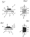
- FIG. 1 and 2 there is the connector, a so-called Sub-D connector from a plug-in area 1 and a Connection area 2.
- the plug area 1 and the connection area 2 are each by a sheet metal part 3, 4, e.g. made of steel, which each have a flange section 5, 6 with a the top view according to FIG. 2 trapezoidal metal collar 7,8 exhibit.
- the flange sections 5, 6 are e.g. by riveting connected to each other and with two mounting holes 9, 10 for fastening the connector to an opening in a provided housing wall, not shown.
- the mating area 1 can be designed as a plug or socket.
- a metal collar 8 of the connection area 2 plate-shaped insulating body 12 e.g. made of glass fiber reinforced Plastic with the 9-pin connector shown nine holes 13 is provided, in each of which a pin contact 14 is embedded.
- the edge of the metal collar 8 is on the insulating body 12 flanged (Fig. 2).
- an adhesive tape 15 the outer circumference of the metal collar 8 of the connection area 2 glued. This creates an upwardly open shape, in which is filled with the liquid resin. You can use a dispensing needle be used, the casting resin first between the pin contact rows and then along the contour the insulating body 12 is applied. As a result of sharp edges to avoid the capillary action of the casting resin filled up to the upper edge of the adhesive tape 15.
- the adhesive tape 15 is removed, whereby the connector shown in Figures 3 and 4 is obtained on the insulating body 12 according to FIG. 2 has a cured cast resin layer 16 which with the trapezoidal outer circumference of the metal collar 8 of the connection area 2 is aligned, i.e. it overlaps the flanged one Edge of the metal collar 8.
- the pin contacts 14 are with their area facing the insulating body 12 tightly into the Cast resin layer 16 embedded.
- the gap becomes 17th between insulating body 12 and metal collar 8 through the cast resin layer 16 tightly closed.
- the thickness d of the cast resin layer 16 can be 3 mm, for example.
Landscapes
- Manufacturing Of Electrical Connectors (AREA)
- Connector Housings Or Holding Contact Members (AREA)
Abstract
Description
- Figur 1 und 2
- eine Seitenansicht bzw. eine Draufsicht auf einen Steckverbinder nach DIN 41 652; und
- Figur 3 und 4
- eine Seitenansicht und eine Draufsicht auf einen mit dem Steckverbinder nach Fig. 1 und 2 hergestellten erfindungsgemäßen Steckverbinder.
Claims (10)
- Steckverbinder mit einer Abdichtung gegen Flüssigkeiten und Gase, mit einem Steckbereich (1) und einem Anschlussbereich (2), die jeweils durch ein Blechteil (3, 4) mit einem Flanschabschnitt (5, 6) und einem in der Draufsicht trapezförmigen Metallkragen (7, 8) gebildet und mit ihren Flanschabschnitten (5, 6) miteinander verbunden sind, wobei in den Metallkragen (8) des Anschlußbereichs (2) ein Isolierkörper (12) angeordnet ist, der mit Bohrungen (13) versehen ist, in denen Einzelkontakte (14) befestigt sind, und zwischen dem Isolierkörper (12) und dem Metallkragen (8) des Anschlußbereichs (2) ein Spalt (17) gebildet ist, dadurch gekennzeichnet, daß die Abdichtung durch eine Schicht (16) aus einem ausgehärteten Gießharz auf dem Isolierkörper (12) gebildet wird, in welche die Einzelkontakte (14) eingebettet sind, wobei der Außenumfang der Gießharzschicht (16) mit dem Außenumfang des Metallkragens (8) des Anschlußbereichs (2) unter Verschluß des Spaltes (17) zwischen dem Isolierkörper (12) und dem Metallkragen (8) fluchtet und die Shore D-Härte der Gießharzschicht wenigstens 30 beträgt.
- Steckverbinder nach Anspruch 1, dadurch gekennzeichnet, dass die Einzelkontakte (14) über die Gießharzschicht (16) nach außen vorstehen.
- Steckverbinder nach Anspruch 1 oder 2, dadurch gekennzeichnet, daß die Dicke (d) der Gießharzschicht (16) 1 bis 4 mm beträgt.
- Steckverbinder nach einem der Ansprüche 1 bis 3, dadurch gekennzeichnet, daß das Gießharz mineralische Füllstoffe enthält.
- Steckverbinder nach einem der vorstehenden Ansprüche, dadurch gekennzeichnet, daß das Gießharz durch eine Polyurethanmasse gebildet wird.
- Verfahren zur Herstellung des Steckverbinders nach einem der vorstehenden Ansprüche, dadurch gekennzeichnet, daß das flüssige Gießharz in eine um den Metallkragen (8) angebrachte, den Isolierkörper (12) überragende Form gefüllt wird, die durch ein auf den Außenumfang des Metallkragens (8) geklebtes Klebeband (15) gebildet wird.
- Verfahren nach Anspruch 6, dadurch gekennzeichnet, daß das flüssige Gießharz eine Viskosität von 1000 bis 15000 mPas aufweist.
- Verfahren nach einem der Ansprüche 6 oder 7, dadurch gekennzeichnet, daß die Topfzeit des Gießharzes auf höchstens 20 min eingestellt wird.
- Verfahren nach einem der Ansprüche 6 bis 8, dadurch gekennzeichnet, daß das Gießharz mineralische Füllstoffe enthält.
- Verfahren nach einem der Ansprüche 5 bis 9, dadurch gekennzeichnet, daß das Gießharz zu einer Polyurethanmasse aushärtet.
Applications Claiming Priority (2)
| Application Number | Priority Date | Filing Date | Title |
|---|---|---|---|
| DE1998158111 DE19858111C2 (de) | 1998-12-16 | 1998-12-16 | Abgedichteter Steckverbinder und Verfahren zu dessen Herstellung |
| DE19858111 | 1998-12-16 |
Publications (2)
| Publication Number | Publication Date |
|---|---|
| EP1011174A2 true EP1011174A2 (de) | 2000-06-21 |
| EP1011174A3 EP1011174A3 (de) | 2002-01-30 |
Family
ID=7891325
Family Applications (1)
| Application Number | Title | Priority Date | Filing Date |
|---|---|---|---|
| EP99118408A Withdrawn EP1011174A3 (de) | 1998-12-16 | 1999-09-16 | Abgedichteter Steckverbinder und Verfahren zu dessen Herstellung |
Country Status (2)
| Country | Link |
|---|---|
| EP (1) | EP1011174A3 (de) |
| DE (1) | DE19858111C2 (de) |
Cited By (1)
| Publication number | Priority date | Publication date | Assignee | Title |
|---|---|---|---|---|
| CN106159529A (zh) * | 2016-08-10 | 2016-11-23 | 深圳永贵盟立科技有限公司 | 一种d‑sub防水连接器及其制作方法 |
Families Citing this family (1)
| Publication number | Priority date | Publication date | Assignee | Title |
|---|---|---|---|---|
| DE102014007460B4 (de) * | 2014-05-21 | 2020-04-16 | Lumberg Connect Gmbh | Steckverbinder |
Family Cites Families (7)
| Publication number | Priority date | Publication date | Assignee | Title |
|---|---|---|---|---|
| DE2323967A1 (de) * | 1973-05-11 | 1974-11-28 | Us Terminals Inc | Anschlusstueck fuer einen elektrischen anschluss |
| US5120268A (en) * | 1990-08-07 | 1992-06-09 | Al Gerrans | Marine electrical connector |
| JP3110494B2 (ja) * | 1991-06-14 | 2000-11-20 | バーグ・テクノロジー・インコーポレーテッド | コネクタ |
| DE4341958A1 (de) * | 1993-12-09 | 1995-06-14 | Abb Patent Gmbh | Vielfach-Flachstecker |
| DE19511056A1 (de) * | 1994-03-30 | 1995-10-05 | Leonische Drahtwerke Ag | Verfahren zum Herstellen eines Kupplungsteils für elektrische Steckverbindungen |
| US5535512A (en) * | 1994-10-12 | 1996-07-16 | Armogan; Lloyd | Method of making a hermetically sealed electrical connector |
| DE19528678C1 (de) * | 1995-07-19 | 1997-01-23 | Ifm Electronic Gmbh | Einbaustecker |
-
1998
- 1998-12-16 DE DE1998158111 patent/DE19858111C2/de not_active Expired - Fee Related
-
1999
- 1999-09-16 EP EP99118408A patent/EP1011174A3/de not_active Withdrawn
Cited By (2)
| Publication number | Priority date | Publication date | Assignee | Title |
|---|---|---|---|---|
| CN106159529A (zh) * | 2016-08-10 | 2016-11-23 | 深圳永贵盟立科技有限公司 | 一种d‑sub防水连接器及其制作方法 |
| CN106159529B (zh) * | 2016-08-10 | 2019-07-02 | 深圳永贵技术有限公司 | 一种d-sub防水连接器及其制作方法 |
Also Published As
| Publication number | Publication date |
|---|---|
| DE19858111A1 (de) | 2000-06-29 |
| EP1011174A3 (de) | 2002-01-30 |
| DE19858111C2 (de) | 2002-05-02 |
Similar Documents
| Publication | Publication Date | Title |
|---|---|---|
| WO1996003852A1 (de) | Wasserdichtes gehäuse mit einer steckverbindung zum schutz von elektronikschaltkreisen | |
| DE19880257B4 (de) | Verfahren zur Herstellung eines Abschirmgehäuses | |
| DE102011121133A1 (de) | Fluiddichte Kontaktdurchführung | |
| DE102013005705A1 (de) | Fluiddichte Kontaktdurchführung | |
| DE102009046467B4 (de) | Leiterbahnstanzgitter mit einer speziellen Oberflächenkontur sowie Steuergerät mit einem solchen Leiterbahnstanzgitter | |
| EP0895449A2 (de) | Elektrisch leitfähige Dichtung und Verfahren zu deren Herstellung | |
| DE102009047329A1 (de) | Flexible Leiterplatte sowie elektrische Vorrichtung | |
| DE102016112566A1 (de) | Verbindungsanordnung für einen elektrisch leitenden Kontakt sowie Verfahren zur Herstellung einer solchen Verbindungsanordnung | |
| DE10044460A1 (de) | Baueinheit und Verfahren zur Herstellung derselben | |
| EP1011174A2 (de) | Abgedichteter Steckverbinder und Verfahren zu dessen Herstellung | |
| EP0121133A2 (de) | Verfahren zur Herstellung eines elektrischen Kunststoffisolators und nach dem Verfahren hergestellter Verbundisolator | |
| DE102009048877A1 (de) | Kabeldurchführung in Steckverbindergehäusen | |
| EP2184962A2 (de) | Elektrische Vorrichtung mit einer elektrischen Bauteileanordnung und mit einem Gehäuse | |
| DE102013226538A1 (de) | Gehäuse für eine elektronische Schaltungsanordnung und dessen Herstellung | |
| DE19708010C2 (de) | Polymer-Stützisolator und Verfahren zu seiner Herstellung | |
| DE2358076A1 (de) | Abgedichtetes verbindungselement fuer isolierte leitungen | |
| DE102015208877B4 (de) | Elektronische Komponente | |
| DE19511056A1 (de) | Verfahren zum Herstellen eines Kupplungsteils für elektrische Steckverbindungen | |
| EP0772959A1 (de) | Wasserdichtes gehäuse mit einer steckverbindung zum schutz von elektronikschaltkreisen | |
| DE19829354C1 (de) | Unterlegscheibe sowie Bauteilverbindung mit einer Unterlegscheibe | |
| EP1365487B1 (de) | Verfahren zur Herstellung eines Gehäuses | |
| DE102013017745A1 (de) | Keramikbauteil mit einem Cermet-Körper | |
| DE10059177A1 (de) | Anordnung mit einem ersten Element und einem damit verbundenen zweiten Element, die insbesondere zum Einsatz in einem Kraftstoffeinspritzventil geeignet ist, und Verfahren zu deren Herstellung | |
| DE102017209278A1 (de) | Elektronische Komponente und Verfahren zur Herstellung einer elektronischen Komponente | |
| DE102004043054B4 (de) | Anordnung mit einer Leiterbahnstruktur mit elektrischen oder elektronischen Bauteilen in einem Schutzgehäuse, Schutzgehäuse hierfür und Verfahren zur Bildung einer Baugruppe |
Legal Events
| Date | Code | Title | Description |
|---|---|---|---|
| PUAI | Public reference made under article 153(3) epc to a published international application that has entered the european phase |
Free format text: ORIGINAL CODE: 0009012 |
|
| AK | Designated contracting states |
Kind code of ref document: A2 Designated state(s): AT BE CH CY DE DK ES FI FR GB GR IE IT LI LU MC NL PT SE |
|
| AX | Request for extension of the european patent |
Free format text: AL;LT;LV;MK;RO;SI |
|
| PUAL | Search report despatched |
Free format text: ORIGINAL CODE: 0009013 |
|
| AK | Designated contracting states |
Kind code of ref document: A3 Designated state(s): AT BE CH CY DE DK ES FI FR GB GR IE IT LI LU MC NL PT SE |
|
| AX | Request for extension of the european patent |
Free format text: AL;LT;LV;MK;RO;SI |
|
| 17P | Request for examination filed |
Effective date: 20020117 |
|
| AKX | Designation fees paid |
Free format text: AT BE CH CY DE DK ES FI FR GB GR IE IT LI LU MC NL PT SE |
|
| GRAP | Despatch of communication of intention to grant a patent |
Free format text: ORIGINAL CODE: EPIDOSNIGR1 |
|
| STAA | Information on the status of an ep patent application or granted ep patent |
Free format text: STATUS: THE APPLICATION HAS BEEN WITHDRAWN |
|
| 18W | Application withdrawn |
Effective date: 20040604 |