EP1011185B1 - Verbessertes Fehlerschutzverfahren - Google Patents
Verbessertes Fehlerschutzverfahren Download PDFInfo
- Publication number
- EP1011185B1 EP1011185B1 EP99307344A EP99307344A EP1011185B1 EP 1011185 B1 EP1011185 B1 EP 1011185B1 EP 99307344 A EP99307344 A EP 99307344A EP 99307344 A EP99307344 A EP 99307344A EP 1011185 B1 EP1011185 B1 EP 1011185B1
- Authority
- EP
- European Patent Office
- Prior art keywords
- fault
- circuit breaker
- output signal
- zone
- line
- Prior art date
- Legal status (The legal status is an assumption and is not a legal conclusion. Google has not performed a legal analysis and makes no representation as to the accuracy of the status listed.)
- Expired - Lifetime
Links
- 238000000034 method Methods 0.000 claims abstract description 25
- 238000005259 measurement Methods 0.000 claims abstract description 21
- 238000012544 monitoring process Methods 0.000 claims abstract description 19
- 238000012545 processing Methods 0.000 claims abstract description 7
- 230000003111 delayed effect Effects 0.000 description 22
- 230000004044 response Effects 0.000 description 12
- 238000004891 communication Methods 0.000 description 10
- 238000001514 detection method Methods 0.000 description 7
- 230000008859 change Effects 0.000 description 4
- 238000004422 calculation algorithm Methods 0.000 description 2
- 230000000694 effects Effects 0.000 description 2
- 238000012986 modification Methods 0.000 description 2
- 230000004048 modification Effects 0.000 description 2
- 238000005070 sampling Methods 0.000 description 2
- 230000001052 transient effect Effects 0.000 description 2
- 230000008901 benefit Effects 0.000 description 1
- 238000004364 calculation method Methods 0.000 description 1
- 239000002775 capsule Substances 0.000 description 1
- 238000010276 construction Methods 0.000 description 1
- 238000009795 derivation Methods 0.000 description 1
- 238000009434 installation Methods 0.000 description 1
- 230000002688 persistence Effects 0.000 description 1
- 230000003068 static effect Effects 0.000 description 1
Images






Classifications
-
- H—ELECTRICITY
- H02—GENERATION; CONVERSION OR DISTRIBUTION OF ELECTRIC POWER
- H02H—EMERGENCY PROTECTIVE CIRCUIT ARRANGEMENTS
- H02H7/00—Emergency protective circuit arrangements specially adapted for specific types of electric machines or apparatus or for sectionalised protection of cable or line systems, and effecting automatic switching in the event of an undesired change from normal working conditions
- H02H7/26—Sectionalised protection of cable or line systems, e.g. for disconnecting a section on which a short-circuit, earth fault, or arc discharge has occured
- H02H7/30—Staggered disconnection
-
- H—ELECTRICITY
- H02—GENERATION; CONVERSION OR DISTRIBUTION OF ELECTRIC POWER
- H02H—EMERGENCY PROTECTIVE CIRCUIT ARRANGEMENTS
- H02H3/00—Emergency protective circuit arrangements for automatic disconnection directly responsive to an undesired change from normal electric working condition with or without subsequent reconnection ; integrated protection
- H02H3/08—Emergency protective circuit arrangements for automatic disconnection directly responsive to an undesired change from normal electric working condition with or without subsequent reconnection ; integrated protection responsive to excess current
- H02H3/093—Emergency protective circuit arrangements for automatic disconnection directly responsive to an undesired change from normal electric working condition with or without subsequent reconnection ; integrated protection responsive to excess current with timing means
Definitions
- This invention relates to improvements in apparatus for the protection of electrical power lines.
- a fault protection circuit which includes a circuit breaker is provided in the electrical line.
- the breaker has a normally closed contact which connects two portions of the line when no fault is present. When a fault is detected, the contact is opened to isolate one part of the line from the other.
- a trip relay is provided which detects the current or voltage flowing in the line to provide an output signal. If the output signal is indicative of a fault on the line, the circuit breaker is opened.
- the known fault protection schemes differ in the way in which the output signal is processed to control the opening of the circuit breaker.
- Two broad categories of scheme are known as non-unit protection and unit protection. Each has its own limitations.
- a non-unit fault protection scheme is the distance protection scheme.
- a single circuit breaker protects a length of line section, for example over the ends 'S' and 'R' as shown in Figure 1(a) .
- a single measurement device (the "relay") provided at a measurement point "M1" adjacent the circuit breaker provides an output signal indicative of the signal on the line.
- the protected portion of line covered by the circuit breaker is divided into a number of zones, typically two zones.
- the first zone, zone 1 may cover up to 80% of the line section from the circuit breaker. This is referred to as the reach point and is shown in Figure 1(a) .
- Zone 2 is normally arranged to cover 50% of the shortest adjacent line beyond the protected line. Again this is shown in Figure 1(a) .
- the zone 1 can be defined using a relay capsule of measuring the impedance of the line up to a certain point. This is known in the art as a distance relay. It is designed to operate its circuit breaker only for faults occurring between the relay location and its reach point.
- the fault can be detected by monitoring the output signal from the relay.
- the circuit breaker is adapted to be opened instantly upon detecting the presence of a fault in zone 1.
- the overall response time of the circuit breaker is chosen to be significantly longer. This provides enough time for an adjacent (remote) circuit breaker on the line nearer to the zone 2 fault to open, hopefully clearing the fault without the need to open the local circuit breaker.
- F2 will be within its zone 1 area causing an instant trip.
- Unit protection techniques have a clear defined protection zone as shown in Figure 1(b) .
- the boundaries are user defined by using information from the local relay and also from a remote relay at the other end of the protected section of line.
- the system effectively makes two point measurements at points "M1" and M2", i.e. from each end of the protected section.
- a communication link is used to transmit information about the system condition from one end of the protected section to the other.
- the relays at both ends can be arranged to trip instantly to isolate the protected portion of the line when a fault occurs on the protected portion, say at "F1".
- the circuit breakers may both be prevented from opening, for instance for a fault at the point "F2".
- unit protection scheme Whilst the unit protection scheme provides more defined zones than the non-unit protection scheme by allowing accurate location of the fault position, it is expensive to implement and the communication links are undesirable.
- a protection relay is provided at each end of a protected portion of a line.
- Each relay is adapted to make an instant fault trip of its associated circuit breaker for a fault occurring within a zone 1 distance along the line.
- This zone 1 typically defines 80% of the line section length. For example, for a fault at position "F1" in the Figure, both circuit breakers will be opened instantly. However, for a fault occurring outside of zone 1 at one relay, only one circuit breaker will be instantly tripped.
- a signal passed along a communical link between the two relays can be used to send information from the relay that has instantly tripped to the other relay. Only if an appropriate signal is received will the other circuit breaker be opened as the fault lies outside its protected zone 1 section. Again, this scheme suffers from the need for a communication link between the relays.
- the document US 3 379 933 discloses an apparatus for protecting a section of a line comprising a local fault protection assembly provided at one end of the section distal from at least one remote fault protection assembly provided at the other side of the section.
- a communication link is provided between the local fault protection assembly and the remote fault protection assembly to eventually trip the circuit breaker of the local fault protection assembly according to a signal transmitted on the communication link.
- An object of the invention is to provide a fault protection scheme which at least partially alleviates the problems present in prior art systems incorporating communication links.
- a first aspect of the invention is defined by the features of independent claim 1.
- the invention therefore provides a method in which unit protection is implemented without the need for a remote communication link between the local and remote circuit breaker. This is made possible by suitable processing of the output signal.
- the remote circuit breaker By operation of the remote circuit breaker we may mean opening or closing of a trip contact of the remote circuit breaker provided in the line. By operating the local circuit breaker, we mean opening or closing the circuit breaker.
- the method may comprise the additional step of substantially instantly opening the local circuit breaker regardless of whether a fault is detected which is within the first zone or outside the first zone. If the output signal from the signal measurement means indicates that the fault has not been cleared after the operation of the remote circuit breaker has been detected, the local circuit breaker may be inhibited from reclosing. If the fault is cleared, the local circuit breaker may be reclosed. This is known as the "instant operation mode".
- An advantage of the instant operation mode is that it offers increased protection by automatically opening the local circuit breaker to isolate the line section for any detected fault condition.
- the circuit breaker cannot be opened instantly. Instead it may be opened after a predetermined time delay.
- the local circuit breaker may be opened at an accelerated time without waiting for the predetermined delay. If the fault has cleared then the local circuit breaker may be inhibited from opening at all. This is known as the "delayed operation mode". Operation in either the instant or delayed mode may be selected during installation of the apparatus.
- the fault protection may be adapted to choose either instant operation or delayed operation adaptively in response to the type of fault which occurs.
- the invention lies, at least in part, in monitoring the output signal from a single measurement sensor at a local circuit breaker to determine the effect of the operation of a remote circuit breaker on the fault signal present on the line to decide how to operate the local circuit breaker.
- the remote fault protection assembly may also be adapted to operate in the same way as the local fault protection assembly described hereinbefore.
- any circuit breaker on the line may operate as a "local” breaker, with adjacent breakers on the line being “remote” breakers.
- the operation of the remote circuit breaker may be detected by monitoring the output signal over time to detect changes in value indicative of opening of a remote breaker.
- a knowledge of the time delay between detecting a fault and the expected closure or opening of adjacent remote breaks can be used to help identify the remote operation.
- the output signal may comprise three output sub-signals, one sub-signal per phase for a three phase line. Any such three phase system may be represented as the sum of three balanced three-phase components; positive sequence having the same phase rotation as the original system, negative sequence having the opposite phase rotation, and zero sequence having no phase rotation. In the event of an unbalanced or asymmetrical fault, negative and zero sequence quantities will be generated. These components can be observed in the output sub-signals and used to identify an initial fault.
- Operation of a remote breaker can be detected by looking for changes in the sub-signals after the initial fault has been detected.
- a fault on the line may be detected by looking for an output signal indicative of an unbalanced current or voltage.
- a system is unbalanced when three phase currents and/or voltage signals are not of equal amplitude and/or the phase differences between successive signals are unequal. It is expected that most fault conditions will provide unbalanced or transient signals.
- the line signal will normally be balanced in a no fault operating condition.
- line signal we mean the current or voltage on the line. This may typically be a sinusoidal three phase voltage or current signal.
- the positive and/or negative and/or zero sequence components may be detected using a real-time processing algorithm.
- One or more ratio signals may be calculated from the RMS values of the sequence components.
- a first ratio may be used to indicate an asymmetrical fault.
- the second ratio may be used to identify a three phase symmetrical fault.
- the first zone may be defined by known distance protection techniques. It may cover approximately 80% of the length of the protected portion of line.
- the output sub-signals may be indicative of the voltage or the current in the phases of the line.
- the current sensing devices may comprise relays such as electromechanical relays or static relays and may be combined with digital or analogue electronic processing means.
- a second aspect of the invention is defined by the features of independent claim 11.
- CB represents circuit breaker.
- I a , I b and I c represent the three phase currents;
- I 1 , I 0 and I 2 represent the positive, zero and negative sequence currents;
- V 1 , V 0 and V 2 represent the three phase voltages;
- V 1 , V 0 and V 2 represent the positive, zero and negative sequence voltages;
- R 1 , and R 2 represent the ratio signals as given in the Equation (11) and (12) respectively; The derivation of the sequence quantities and the ratio signals will be given in the equations (1)-(12) hereinafter.
- the present invention covers protected zone with clearly defined boundary using one point measurement only. In another word, it can be considered to be a unit protection apparatus without the need for any communication link.
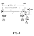
- FIG. 2 is used as an example to describe the invention.
- this is a multi-section power line system with the circuit breaker means R11 and R12 installed at each end (ends 'S' and 'R') of the protected line section L-1.
- B11 and B12 are three phase circuit breakers used to protect line section L-1.
- R21 and B21 are protection apparatus and three phase circuit breaker responsible for the protection of line section L-2 at the end 'R'.
- the present invention is incorporated into the apparatus of the invention R11, the protection zone of the apparatus covers the line section L-1 which is the line section between the end 'S' and 'R'.
- the fault detection of R11 covers both Zone 1 and Zone 2 from the end 'S'.
- the performance of the apparatus is demonstrated by its responses to different fault conditions, in particular to the faults outside Zone 1 reach of the R11 on the protected line (for example, at the 'F2' point on line section L-1) and faults outside the protection zone within the Zone 2 reach of the R11 (fro example, at the 'F3' point on line section L-2).
- the word 'operation' means to open or close circuit breaker(s), which could be one of the three phase circuit breaker (the single phase tripping or closing) or the three phase circuit breaker concurrently (the three phase tripping or closing).
- the word 'operation' means to open or close circuit breaker(s), which could be one of the three phase circuit breaker (the single phase tripping or closing) or the three phase circuit breaker concurrently (the three phase tripping or closing).
- the three phase circuit breakers will normally open independently upon the current which flows through the individual circuit breaker cross zero value.
- there could be a time delay between the opening of each phase circuit breaker is very short (normally within a few mili-second), it has no effect on the invention presented here and will not be demonstrated in the following examples.
- the fault protection apparatus uses a distance technique (as shown in Figure 1(a) ) as the means for fault detection and protection.
- the basic principle of the distance protection technique is well-known.
- the apparatus makes decision as whether to instantly or delayed operate the associated circuit breaker(s) depending on the system and fault condition. This is made by monitoring the output of the sensing means associated with each circuit breaker to detect the operation of a "remote breaker".
- the R11 at the end 'S' will first assess the severity of the fault impact on the power line system to decide to which operation mode to be used in this fault condition. That is whether to instantly or delayed trip the associated circuit breakers B11.
- a criterion for the severity of a fault with respect to the levels of the faulted voltage and current signals can be derived and set in advance. If the preset criterion is met, R11 should enter the instant operation mode. Otherwise, the delayed operation mode will be adopted.
- the apparatus can also be set to operate under instant or delayed operation mode alone.
- the apparatus R11 will instantly trip its associated circuit breakers B11 for a fault detected within Zone 2 reach of R11. After opening the associated circuit breakers B11, the apparatus R11 will start to detect whether the fault is inside the protected zone or not by identifying the operation performed by the remote circuit breaker(s). An in zone fault can be assumed if the circuit breakers B12 on the protected line at the end 'R' opens and the fault condition is still persistence after the operation. This effectively means that the remote relay R12 detects an in zone fault and trips the faulted section L-1. In this situation, the R11 is inhibited from immediate reclosing operation. Otherwise, the R11 will issue a reclosing command and close its associated circuit breaker B11 when an out zone operation by the remote circuit breaker (for example, the B21) is detected and the fault is isolated from the protected line section L-1.
- the remote circuit breaker for example, the B21
- the R11 Since the fault is beyond the Zone 1 reach of the apparatus R11, therefore the impact to the system is comparatively light and it is very likely the R11 will enter the delayed operation mode. In this mode, the R11 will wait while detecting the breaker operation at the end 'R'. The apparatuses at the end 'R' on different line sections can easily make decision due to the fault is very close to their locations and trip the corresponding faulted section. The R11 at the end 'S' will then detect and identify whether the circuit breaker B12 on the section L-1 at the remote end have tripped or not. Again, the tripping of the breaker B12 means that the fault is inside of the protected zone or on the remote busbar associated to the protected line section L-1. In both cases, the R11 will issue a tripping command to isolate the protected line section L-1. Otherwise, R11 will give no response if the remote circuit breaker outside the protected line (for example, the B21) operates to isolate the fault from line section L-1.
- the three phase currents and voltages will be in an unbalanced or transient operating condition for a fault existing on the line and will resume balanced and stable operating condition if the fault is cleared by the opening of circuit breaker(s) to isolate the faulted section(s). It is well-know that most faults are asymmetrical and therefore generated negative and zero sequence quantities.
- the apparatus relies on the detection of the presence of the negative and zero sequence quantities to decide whether a system is in a balanced or unsymmetrical faulted condition and the operation performed by the remote breaker.
- the fault protection apparatus may be configured to operate in a combined operation mode in which it can operate in both modes adaptively. Which operating mode is employed will depend on the type of fault which has occurred. For example, it may operate a delayed mode for a single or two phase fault when three phase operation is adopted, yet instant mode when a three phase fault or single phase fault occurs when single phase breaker operation is adopted.
- the positive, negative and zero sequence quantities are first derived through a real-time processing algorithm.
- the Root-Mean-Square (known as RMS) values of these sequence quantities are then computed and the levels of which are compared and used to determine the system condition.
- the changes in these quantities are used to identify the operation of remote circuit breaker(s).
- S 1 S A + a S B + a 2 ⁇ S C / 3
- S 2 S A + a 2 ⁇ S B + a ⁇ S C / 3
- S 0 S A + S B + S C / 3
- S A , S B and S C are three phase power frequency voltages or currents
- S 1 , S 2 and S 0 are positive, negative and zero sequence quantities.
- S 1 S A + S B ⁇ e - j ⁇ 2 ⁇ T 3 + S C ⁇ e - j ⁇ T 3 / 3
- S 2 S A + S B ⁇ e - j ⁇ T 3 + S C ⁇ e - j ⁇ 2 ⁇ T 3 / 3
- S 0 S A + S B + S C / 3
- T is the period for power frequency, which can be either 50 or 60 Hz.
- Equation (5) The way to speed up calculation is to reduce the required samples, that is to reduce the power of the 'e' in equation (2).
- Equ.(9) only requires one sample delay to compute the positive and negative sequence quantities, therefore significantly increase the speed of the computation.
- Two ratio signals are used to detect whether a system is in a balanced operation or not. Firstly, the change in the zero and negative sequence quantities with respect to the change of the positive sequence quantity is used as the main criterion to detect whether the system is in a balanced operation condition or not.
- the signal R 1 will be of zero value under no fault or symmetrical fault condition since there is no presence of negative and zero sequence quantities, and will be increased to a level well above zero if an unsymmetrical fault present on the system.
- the signal R 2 Under the symmetrical fault condition, the signal R 2 will increase to a level and return to zero after the clearance of the fault from the system.
- the theoretical values for the signal R 1 will be '1' for phase to phase fault and '2' for phase to earth fault with remote circuit breaker open.
- the level of signal R 2 will be well above '1' deepening on the pre- and post fault system condition.
- a preset threshold above zero level (say between 0.2 and 0.4) can be used to determine the system fault condition by examining whether the one of the two ratio signals R 1 and R 2 has exceeded it or not.
- Figure 3 shows the responses of the apparatus for a typical in zone single phase to earth fault ('a'-'e') near busbar 'R' on the line section L-1 during the periods of pre-fault, post fault with breaker operations.
- 3(1) shows the level of three phase current signals
- 3(2) shows the sequence current signals
- 3(3) shows the ratio signal R 1 as given in Equation(11).
- the three phase current signals are of the same level and the zero and negative sequence currents remain as zero.
- the apparatus R12 on line section L-1 at the end 'R' detects the fault, issues a tripping command and subsequently opens the associated circuit breaker B12.
- the ratio signal R 1 increases to a level above the preset threshold after the fault inception at time T 1 as shown in Figure 3(3) .
- the phase 'b' and 'c' of line section L-1 become open circuit and I b and I c drop to zero values.
- the fault on phase 'a' has not been cleared by the remote circuit breaker operation since it is inside the protected zone.
- the faulted phase current I a and the negative, zero sequence current remain at high level.
- the time delay from the fault inception at time T 1 to the opening of the circuit breaker B11 at time T 3 mainly consists of 2 time periods, the t12 and t23.
- t12 consists of the time period from the fault inception to the operation of the end 'R' circuit breaker B12 which is the time taken by the R12 to detect the presence of a fault (normally takes about one power frequency cycle) and the time taken for circuit breaker B12 to open (normally takes between one to three cycles depending on the circuit breaker used).
- t23 consists of the time taken for the apparatus R11 to identify the operation of breaker B12 plus the response time of the circuit breaker B11.
- the total time delay for delayed operation mode will be the time period of t23, which is approximately 2 to 4 cycles depending on the circuit breaker used.
- Figure 4 shows the corresponding responses for an out zone single phase to earth fault occurring near busbar 'R' on line section L-2. Since the fault is close to the previous fault location, the phase and sequence current signals as shown in Figure 4(1) and 4(2) are about the same level as shown in Figure 3(1) and 3(2) before the opening of the end 'R' breaker B21 at time T 1 . After the opening of the circuit breaker B21 at time T 2 , the fault is isolated from the protected section L-1, and the system resumes balanced operation. Consequently, the faulted phase current I a returns back to pre-fault level and the negative, zero sequence currents drop back to zero as shown in Figure 4(2) . The signal ratio then drops to a level well below the threshold as shown in Figure 4(3) , which inhibits the apparatus R11 at the end 'S' from making a tripping decision for this out zone fault condition.
- Figure 5 shows the responses for a phase to phase ('a'-'b') in zone fault close to busbar 'R' on line section L-1.
- the system enters an unbalanced operation condition after the fault inception at time T 1 .
- the zero sequence current is kept at zero because the fault does not involve earth.
- the opening of the circuit breaker B12 at time T 2 dose not clear the fault on line section L-1, the significant negative sequence current present keeps the signal ratio well about the preset threshold as shown in Figure 5(3) .
- the unfaulted phase current I c drops to zero due to the opening of the circuit breaker B12.
- the apparatus R11 detects this in zone fault condition and issues a tripping command and subsequently opens the circuit breaker B11 at time T 3 , the faulted section L-1 is isolated.
- Figures 7 and 8 show the system responses to a single phase ('a') in zone and out zone high impedance faults respectively when single phase breaker operation is applied.
- Figures 7(1) and 8(1) there is little changes in magnitudes of the faulted phase current between the period of fault inception at time T 1 the breaker operation at time T 2 , consequently the sequence current as shown in figures 7(2) and 8(2) .
- the ratio signal is kept below the threshold as shown in both Figures 7(3) and 8(3) .
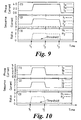
- Figures 9 and 10 show the responses of the apparatus to the three phase in zone and out zone faults respectively.
- Figures 9(1) and 10(1) all the three phase currents increase to the same high level after the fault inception at time T 1 .
- the positive sequence currents increase greatly as shown in Figures 9(2) and 10(2) . Since these are balanced fault conditions, the zero and negative sequence currents remain as zero.
- the positive sequence current stays at high level for the in zone fault condition as shown in Figure 9(2) and returns to pre-fault level for out zone fault condition as shown in Figure 10(2) .
- the signal ratio R 1 as given in Equation(11) remain below the threshold in both cases through the entire period as shown in Figures 9(3) and 10(3) . This makes the detection of the circuit breaker operation impossible based on this ratio signal.
- the positive sequence current changes drastically during the period as shown in Figures 9(2) and 10(2) .
- the ratio signals R 2 as given in Equation(12) show the changes in the positive sequence current with respect to its pre-fault level from which the remote in zone and out zone breaker operation can be clearly identified.
- the high level of the R 2 enables R11 to make a tripping decision and subsequently the breaker B11 opens at time T 3 as shown in Figure 9(3) .
- the level of the R 2 signal returns back to zero after the opening of circuit breaker B21 at time T 2 which inhibits the R11 from making a tripping decision.
- the apparatus can either adopt the instant operation mode only if required or on-line make the decision to which mode to use adapting to the system and fault condition.
- the instant opening the end 'S' circuit breaker B11 will open circuit the line at one end, there will be no current measurement available. Therefore, in this operation mode, the apparatus of the invention relies on the measurement of the voltage signals for the detection and identification of remote breaker operation. It is expected that the voltage transducers are installed on the line side of the circuit breaker which is the normal practice.
- Cases 5 and 6 are examples demonstrating the performance of the apparatus under instant operation mode using voltage measurements.
- Figures 11 and 12 show the responses of the invented apparatus to the in zone and out zone phase to phase ('a'-'b') faults respectively.
- Figures 11(1), 11(2), 12(1) and 12(2) show the phase and sequence voltages during the periods of pre-fault, post-fault with breaker operations at both ends 'S' and 'R'.
- the sequence voltage signals drop to a level close to zero.
- the ratio signal increases to a level over the threshold after fault inception, and further increases to a very high level after the breaker opening.
- the apparatus R11 at the end 'S' is inhibited from reclosing for this in zone fault condition.
- the opening of the remote circuit breaker B21 isolates the fault from line section L-1, the system returns back to balanced operation condition.
- the positive sequence voltage drops after the fault inception and return close to its pre-fault level after the breaker opening.
- the negative sequence voltage increases after the fault inception and drops back after the breaker opening.
- the signal ratio drops back to below the threshold, which enables the apparatus R11 to reclose the end 'S' breaker B11 at time T 3 .
- Figures 13 and 14 show the responses of the apparatus to the in zone and out zone single phase to earth faults ('a'-'e') respectively. In both cases, the single phase operation of the circuit breaker is used. As shown in Figures 13(2) and 14(2) , at time T 2 , the faulted phase of the circuit breakers B11 and B12 open for the in zone fault case, and that of the B11 and B21 open for the out zone fault case. For the in zone fault, since the fault still exists on the line section L-1, this results in the significantly high negative and zero sequence voltages and the sustain high level of the ratio signal as shown in Figure 3(3) . As a result, the R11 is inhibited from making a reclosing decision.
Landscapes
- Emergency Protection Circuit Devices (AREA)
- Heat Treatment Of Steel (AREA)
- Stabilization Of Oscillater, Synchronisation, Frequency Synthesizers (AREA)
- Optical Communication System (AREA)
- Use Of Switch Circuits For Exchanges And Methods Of Control Of Multiplex Exchanges (AREA)
- Liquid Crystal Substances (AREA)
Claims (11)
- Verfahren zum Schützen eines Zeilenabschnittes (L-1) mit Hilfe einer lokalen Fehlerschutz-Anordnung (R11) an dem einen Ende (S) des Abschnittes (L-1) mit Abstand von wenigstens einer entfernten Fehlerschutz-Anordnung (R12) auf der anderen Seite (R) des Abschnittes (L-1), wobei jede Anordnung (R11, R12) einen Leistungsschalter (B11, B12), eine Zeilensignal-Meßvorrichtung, die in der Lage ist, ein Ausgangssignal zu erzeugen, das die Spannung oder den Strom in der Leitung anzeigt, sowie eine Signalbearbeitungs-Vorrichtung aufweist, die das Ausgangssignal bearbeiten kann, um für den Fall ein Fehlersignal zu erzeugen, daß das Ausgangssignal das Vorhandensein eines Fehlers (F1, F2) in der Leitung anzeigt, ferner umfassend Schritte zur Überwachung des Ausgangssignals von der Signalmeßvorrichtung am Ort des Leistungsschalters (B11), um dadurch das Vorhandensein eines Fehlers (F1) in einer ersten Zone festzustellen, die sich über wenigstens einen Teil des Abschnittes von dem lokalen Leistungsschalter (B11) oder außerhalb dieser ersten Zone erstreckt und für den Fall, daß das Ausgangssignal einen Fehler (F1) in der ersten Zone anzeigt, im wesentlichen sofort den lokalen Leistungsschalter (B11) öffnet, dadurch gekennzeichnet, daß für den Fall, daß der Fehler (F2) sich außerhalb der ersten Zone befindet, der Betrieb des entfernten Leistungsschalter (B12) durch Überwachen des Ausgangssignals der lokalen Signalmeßvorrichtung festgestellt wird, wobei die Überwachung des Ausgangssignals zur Bestimmung des Zustandes des Leitungsabschnittes (L-1) dient, nachdem der entfernt liegende Leistungsschalter (B12) betätigt worden ist, wobei der lokale Leistungsschalter (B12) für den Fall betätigt wird, daß der Zustand einem vorher bestimmten Kriterium entspricht.
- Verfahren nach Anspruch 1, gekennzeichnet durch den zusätzlichen Schritt, daß im wesentlichen momentan der lokale Leistungsschalter (B11) geöffnet wird, und zwar unabhängig davon, ob der Fehler (F1, F2) festgestellt wird, der in der ersten Zone oder außerhalb der ersten Zone liegt.
- Verfahren nach Anspruch 2, dadurch gekennzeichnet, daß für den Fall, daß das Ausgangssignal von der Signalmeßvorrichtung anzeigt, daß der Fehler (F1, F2) nicht beseitigt worden ist, nachdem die Betätigung des entfernt liegenden Leistungsschalters (B12) festgestellt wurde, der lokale Leistungsschalter (B11) daran gehindert wird, sich wieder zu schließen.
- Verfahren nach Anspruch 3, dadurch gekennzeichnet, daß für den Fall, daß der Fehler (F1, F2) beseitigt ist, der lokale Leistungsschalter (B11) wieder geschlossen wird.
- Verfahren nach Anspruch 1, dadurch gekennzeichnet, daß für den Fall, daß durch Überwachen des Ausgangssignals, das sich nicht in der ersten Zone befindet, ein Fehler (F2) festgestellt wird, der Leistungsschalter (B11) nach einer vorbestimmten Zeitverzögerung geöffnet wird.
- Verfahren nach Anspruch 5, dadurch gekennzeichnet, daß für den Fall, daß durch Überwachen des Ausgangssignals der Betrieb des entfernten Leistungsschalters (B12) festgestellt wird und anzeigt, daß der Fehler (F1, F2) in der Leitung nach diesem Betrieb noch vorhanden ist, der lokale Leistungsschalter (B11) kurzzeitig geöffnet wird, ohne auf die vorbestimmte Verzögerung zu warten.
- Verfahren nach Anspruch 5 oder 6, dadurch gekennzeichnet, daß für den Fall, daß der Fehler (F1, F2) behoben worden ist, der lokale Leistungsschalter (B11) am Öffnen gehindert wird.
- Verfahren nach einem der vorhergehenden Ansprüche, dadurch gekennzeichnet, daß der Betrieb der entfernt liegenden Fehlerschutz-Anordnung (R12) durch Überwachen des Ausgangssignals über eine Zeitspanne festgestellt wird, um Änderungen im Wert zu ermitteln, der für das Öffnen eines Leistungsfiernschalters (B12) kennzeichnend ist.
- Verfahren nach Anspruch 8, dadurch gekennzeichnet, daß die Kenntnis der zeitlichen Verzögerung zwischen der Feststellung eines Fehlers (F1, F2) und dem erwarteten Schießen oder Öffnen der benachbarten Fernschalter (B12) zur Identifizierung des Fernbetriebs verwendet wird.
- Verfahren nach einem der vorhergehenden Ansprüche, dadurch gekennzeichnet, daß die Stromabtast-Vorrichtungen Relais aufweisen.
- Gerät zum Schutz eines Abschnitts (L-1) einer Leitung, umfassend eine lokale Fehlerschutz-Anordnung (R11), die an dem einen Ende (S) des Abschnitts (L-1) vorgesehen ist, das von wenigstens einer entfernten Fehlerschutz-Anordnung (R12) beabstandet ist, die auf der anderen Seite (R) des Abschnitts (L-1) vorhanden ist, wobei jede Anordnung (R11, R12) einen Leistungsschalter (B11, B12) und eine Leitungssignal-Meßeinrichtung aufweiset, die ein Ausgangssignal erzeugen kann, das für die Spannung oder den Strom in der Leitung kennzeichnend ist, und wobei eine SignalverarbeitungsEinrichtung vorhanden ist, die das Ausgangssignal verarbeiten kann, um für den Fall ein Fehlersignal zu erzeugen, daß das Ausgangssignal das Vorhandensein eines Fehlers (F1, F2) in der Leitung anzeigt, wobei das Gerät eine Vorrichtung zur Überwachung des Ausgangssignals von der Signalmeßeinrichtung an dem lokalen Leistungsschalter (B11) aufweist, um das Vorhandensein eines Fehlers (F) in einer ersten Zone zu ermitteln, die sich über wenigstens einen Teil von dem lokalen Schalter (B11) aus oder außerhalb dieser ersten Zone erstreckt, und wobei eine Einrichtung zur Steuerung des Leistungsschalters (B11) vorhanden ist, so daß für den Fall, daß das Ausgangssignal einen Fehler (F1) in der ersten Zone anzeigt, die Steuervorrichtung ein im wesentlichen sofortiges Öffnen des lokalen Leistungsschalters (B11) bewirkt, dadurch gekennzeichnet, daß für den Fall, daß der Fehler (F2) außerhalb der ersten Zone liegt, die Überwachungs-Einrichtung in der Lage ist, den Betrieb des Leistungs-Fernschalters (B12) durch Überwachen des Ausgangssignales von der lokalen Signalmeßvorrichtung festzustellen, und daß die Überwachungs-Vorrichtung des weiteren in der Lage ist, das Ausgangssignal zu überwachen, um den Zustand des Abschnitts (L-1) in der Leitung festzustellen, nachdem der Leistungsfernschalter (B12) betätigt worden ist, wobei schließlich die Steuer-Vorrichtung den lokalen Leistungsschalter (B11) für den Fall betätigen kann, daß der Fehlerzustand ein vorbestimmtes Kriterium erfüllt.
Applications Claiming Priority (2)
| Application Number | Priority Date | Filing Date | Title |
|---|---|---|---|
| GBGB9820141.1A GB9820141D0 (en) | 1998-09-17 | 1998-09-17 | Improved fault protection scheme |
| GB9820141 | 1998-09-17 |
Publications (3)
| Publication Number | Publication Date |
|---|---|
| EP1011185A2 EP1011185A2 (de) | 2000-06-21 |
| EP1011185A3 EP1011185A3 (de) | 2002-01-23 |
| EP1011185B1 true EP1011185B1 (de) | 2010-11-03 |
Family
ID=10838935
Family Applications (1)
| Application Number | Title | Priority Date | Filing Date |
|---|---|---|---|
| EP99307344A Expired - Lifetime EP1011185B1 (de) | 1998-09-17 | 1999-09-16 | Verbessertes Fehlerschutzverfahren |
Country Status (7)
| Country | Link |
|---|---|
| US (1) | US6369996B1 (de) |
| EP (1) | EP1011185B1 (de) |
| CN (1) | CN100388585C (de) |
| AT (1) | ATE487260T1 (de) |
| CA (1) | CA2282625C (de) |
| DE (1) | DE69942906D1 (de) |
| GB (2) | GB9820141D0 (de) |
Families Citing this family (34)
| Publication number | Priority date | Publication date | Assignee | Title |
|---|---|---|---|---|
| US6469629B1 (en) * | 1999-02-12 | 2002-10-22 | General Electric Company | Distributed logic in multiple protective relays |
| FR2791823B1 (fr) * | 1999-03-30 | 2001-05-11 | Electricite De France | Dispositif et procede de protection d'une ligne d'un reseau de lignes d'alimentation en energie electrique |
| DE10014929C2 (de) * | 2000-03-20 | 2002-07-11 | Siemens Ag | Verfahren zum Durchführen einer automatischen Wiedereinschaltung und Wiedereinschalteinrichtung |
| GB2375242A (en) * | 2001-05-03 | 2002-11-06 | Alstom | Protecting a section of an electrical power line |
| GB0120748D0 (en) | 2001-08-25 | 2001-10-17 | Lucas Aerospace Power Equip | Generator |
| JP2003070151A (ja) * | 2001-08-27 | 2003-03-07 | Toshiba Corp | 保護継電装置 |
| GB0127745D0 (en) * | 2001-11-20 | 2002-01-09 | Alstom | Protection of double circuit power lines |
| JP3830824B2 (ja) * | 2002-01-28 | 2006-10-11 | 株式会社東芝 | ディジタル形方向継電器 |
| US7532955B2 (en) * | 2002-02-25 | 2009-05-12 | General Electric Company | Distributed protection system for power distribution systems |
| US7058482B2 (en) | 2002-02-25 | 2006-06-06 | General Electric Company | Data sample and transmission modules for power distribution systems |
| US7747356B2 (en) | 2002-02-25 | 2010-06-29 | General Electric Company | Integrated protection, monitoring, and control system |
| AU2003217663A1 (en) * | 2002-02-25 | 2003-09-09 | General Electric Company | Method and system for conditionally triggered system data capture |
| US7111195B2 (en) * | 2002-02-25 | 2006-09-19 | General Electric Company | Method and system for external clock to obtain multiple synchronized redundant computers |
| GB2388482B (en) * | 2002-05-07 | 2005-06-15 | Alstom | Improved power line protection |
| JP3857195B2 (ja) * | 2002-07-09 | 2006-12-13 | 株式会社東芝 | 距離継電装置 |
| JP4020304B2 (ja) * | 2002-08-09 | 2007-12-12 | 株式会社東芝 | 地絡方向継電器および地絡方向継電装置 |
| US7636616B2 (en) | 2003-02-25 | 2009-12-22 | General Electric Company | Protection system for power distribution systems |
| US7039822B2 (en) * | 2003-02-27 | 2006-05-02 | Promos Technologies Inc. | Integrated circuit memory architecture with selectively offset data and address delays to minimize skew and provide synchronization of signals at the input/output section |
| GB2401467B (en) * | 2003-05-09 | 2006-01-25 | Autoliv Dev | Improvements in or relating to a movable or removable unit for a motor vehicle |
| US6833711B1 (en) * | 2003-08-01 | 2004-12-21 | Schweitzer Engineering Laboratories, Inc. | Protective relay for powers systems having dependable out-of-step blocking capability |
| JP2005168108A (ja) * | 2003-11-28 | 2005-06-23 | Tm T & D Kk | 保護継電装置 |
| DE102007008191B4 (de) * | 2007-02-09 | 2009-02-05 | Drewag - Stadtwerke Dresden Gmbh | Verfahren und Datenverarbeitungssystem zur Ermittlung der Anregebedingungen eines ortsfernen Reserveschutzsystems für Mittel- und Hochspannungsleitungen |
| CN101897094B (zh) * | 2007-12-14 | 2013-07-17 | Abb技术有限公司 | 故障方向确定 |
| WO2011156400A1 (en) | 2010-06-07 | 2011-12-15 | Abb Research Ltd. | Systems and methods for characterizing fault-clearing devices |
| WO2014018909A1 (en) | 2012-07-27 | 2014-01-30 | San Diego Gas & Electric Company | System for detecting a falling electric power conductor and related methods |
| CN103066578B (zh) * | 2013-01-09 | 2015-12-09 | 广东电网公司电力调度控制中心 | 站域零序电流保护方法与系统 |
| US9379534B2 (en) * | 2013-03-13 | 2016-06-28 | Consolidated Edison Company Of New York, Inc. | Recloser device and method of operation |
| CN103296652B (zh) * | 2013-05-19 | 2016-03-02 | 国家电网公司 | 输电线路单相接地故障零序电压保护方法 |
| US11137436B2 (en) | 2017-09-22 | 2021-10-05 | Schweitzer Engineering Laboratories, Inc. | Secure traveling wave distance protection in an electric power delivery system |
| US10989752B2 (en) | 2017-09-22 | 2021-04-27 | Schweitzer Engineering Laboratories, Inc. | Distance protection using traveling waves in an electric power delivery system |
| US11038342B2 (en) | 2017-09-22 | 2021-06-15 | Schweitzer Engineering Laboratories, Inc. | Traveling wave identification using distortions for electric power system protection |
| CN110061474B (zh) * | 2019-04-16 | 2021-05-14 | 华南理工大学 | 一种识别并防止和应涌流导致变压器差动保护动作的方法 |
| CN111810300B (zh) * | 2020-07-03 | 2021-08-06 | 东方电气自动控制工程有限公司 | 燃气轮机保护装置 |
| CN112260220B (zh) * | 2020-09-21 | 2023-02-24 | 广东冠能电力科技发展有限公司 | 纵横式零序过流保护方法及系统 |
Family Cites Families (11)
| Publication number | Priority date | Publication date | Assignee | Title |
|---|---|---|---|---|
| US1280739A (en) * | 1915-06-03 | 1918-10-08 | John B Jameson | Piston-ring. |
| GB1084951A (en) * | 1964-01-01 | 1967-09-27 | English Electric Co Ltd | Electrical protective relay arrangement |
| GB1090862A (en) | 1964-03-02 | 1967-11-15 | English Electric Co Ltd | Electrical protective relays |
| CH493126A (de) * | 1969-11-21 | 1970-06-30 | Sprecher & Schuh Ag | Distanzschutzanordnung in einem vermaschten elektrischen Netz |
| US4528611A (en) * | 1983-02-22 | 1985-07-09 | Westinghouse Electric Corp. | Relay for pilot protection of electrical power lines |
| US4484245A (en) * | 1983-06-17 | 1984-11-20 | Westinghouse Electric Corp. | Directional comparison blocking protective relay system |
| US4674002A (en) * | 1986-04-08 | 1987-06-16 | Westinghouse Electric Corp. | Directional comparison blocking system |
| US4725914A (en) * | 1986-12-16 | 1988-02-16 | Westinghouse Electric Corp. | Protective relay system for performing selective-pole trip determination |
| GB8727490D0 (en) | 1987-11-24 | 1987-12-23 | Nat Res Dev | Detecting faults in transmission circuits |
| US4896241A (en) * | 1989-02-28 | 1990-01-23 | Westinghouse Electric Corp. | Directional comparison blocking protective relay system |
| US5838525A (en) * | 1997-04-15 | 1998-11-17 | Abb Power T&D Company, Inc. | High speed single-pole trip logic for use in protective relaying |
-
1998
- 1998-09-17 GB GBGB9820141.1A patent/GB9820141D0/en not_active Ceased
-
1999
- 1999-09-16 EP EP99307344A patent/EP1011185B1/de not_active Expired - Lifetime
- 1999-09-16 DE DE69942906T patent/DE69942906D1/de not_active Expired - Lifetime
- 1999-09-16 AT AT99307344T patent/ATE487260T1/de not_active IP Right Cessation
- 1999-09-16 CA CA2282625A patent/CA2282625C/en not_active Expired - Fee Related
- 1999-09-16 US US09/397,544 patent/US6369996B1/en not_active Expired - Fee Related
- 1999-09-17 CN CNB99122468XA patent/CN100388585C/zh not_active Expired - Fee Related
- 1999-09-17 GB GB9921880A patent/GB2341738B/en not_active Expired - Fee Related
Also Published As
| Publication number | Publication date |
|---|---|
| GB2341738A (en) | 2000-03-22 |
| CA2282625C (en) | 2011-08-02 |
| ATE487260T1 (de) | 2010-11-15 |
| GB2341738B (en) | 2002-08-14 |
| CN100388585C (zh) | 2008-05-14 |
| GB9921880D0 (en) | 1999-11-17 |
| CN1256540A (zh) | 2000-06-14 |
| EP1011185A3 (de) | 2002-01-23 |
| DE69942906D1 (de) | 2010-12-16 |
| EP1011185A2 (de) | 2000-06-21 |
| US6369996B1 (en) | 2002-04-09 |
| CA2282625A1 (en) | 2000-03-17 |
| GB9820141D0 (en) | 1998-11-11 |
Similar Documents
| Publication | Publication Date | Title |
|---|---|---|
| US6369996B1 (en) | Fault protection scheme | |
| US6914762B2 (en) | Protection of electrical power lines | |
| EP2485354B1 (de) | Schutzsystem für ein Stromnetz basierend auf der Induktivität eines Netzabschnittes | |
| EP2780998B1 (de) | Ausfallschutz in gemischten hochspannungsleitungen | |
| EP0987807B1 (de) | Fehlerschutzgerät | |
| EP2139087B1 (de) | Schutzschalter mit verbesserter Wiederschließungsfunktion | |
| US20020101229A1 (en) | Line differential protection system for a power transmission line | |
| EP1207610A2 (de) | System für die Auswahl des Fehlertyps zur Fehleridentifikation in einem elektrischen Energieversorgungssystem | |
| EP1313194A2 (de) | Schutz von Doppelenergieleitungen | |
| US5103365A (en) | Downed conductor automatic detecting device | |
| WO2011041356A2 (en) | System and method for polyphase ground-fault circuit-interrupters | |
| JP3284589B2 (ja) | 送電線の保護方法及び保護継電装置 | |
| US7102866B2 (en) | Power line protection | |
| US7961445B2 (en) | Method of detecting fault extinction during a three-phase autoreclosing cycle in an AC transmission line | |
| EP3830920B1 (de) | Verfahren und vorrichtung zur überwachung eines spannungswandlers | |
| JP2004080839A (ja) | 地絡方向継電器および地絡方向継電装置 | |
| EP2328249B1 (de) | Wiederverschlussvorrichtung für eine stromleitung | |
| EP2595264B1 (de) | Schutzrelaisvorrichtung | |
| US11962140B2 (en) | Coordination of protective elements in an electric power system | |
| JP3832700B2 (ja) | 母線保護継電装置 | |
| Bo et al. | Adaptive non-communication protection scheme for power lines |
Legal Events
| Date | Code | Title | Description |
|---|---|---|---|
| PUAI | Public reference made under article 153(3) epc to a published international application that has entered the european phase |
Free format text: ORIGINAL CODE: 0009012 |
|
| AK | Designated contracting states |
Kind code of ref document: A2 Designated state(s): AT BE CH CY DE DK ES FI FR GB GR IE IT LI LU MC NL PT SE |
|
| AX | Request for extension of the european patent |
Free format text: AL;LT;LV;MK;RO;SI |
|
| PUAL | Search report despatched |
Free format text: ORIGINAL CODE: 0009013 |
|
| AK | Designated contracting states |
Kind code of ref document: A3 Designated state(s): AT BE CH CY DE DK ES FI FR GB GR IE IT LI LU MC NL PT SE |
|
| AX | Request for extension of the european patent |
Free format text: AL;LT;LV;MK;RO;SI |
|
| RIC1 | Information provided on ipc code assigned before grant |
Free format text: 7H 02H 7/26 A, 7H 02H 7/30 B |
|
| 17P | Request for examination filed |
Effective date: 20020524 |
|
| AKX | Designation fees paid |
Free format text: AT BE CH CY DE DK ES FI FR GB GR IE IT LI LU MC NL PT SE |
|
| RAP1 | Party data changed (applicant data changed or rights of an application transferred) |
Owner name: ALSTOM UK |
|
| RAP1 | Party data changed (applicant data changed or rights of an application transferred) |
Owner name: AREVA T&D UK LTD. |
|
| 17Q | First examination report despatched |
Effective date: 20071213 |
|
| GRAP | Despatch of communication of intention to grant a patent |
Free format text: ORIGINAL CODE: EPIDOSNIGR1 |
|
| RIN1 | Information on inventor provided before grant (corrected) |
Inventor name: BO, ZHIQIAN |
|
| GRAS | Grant fee paid |
Free format text: ORIGINAL CODE: EPIDOSNIGR3 |
|
| GRAA | (expected) grant |
Free format text: ORIGINAL CODE: 0009210 |
|
| AK | Designated contracting states |
Kind code of ref document: B1 Designated state(s): AT BE CH CY DE DK ES FI FR GB GR IE IT LI LU MC NL PT SE |
|
| REG | Reference to a national code |
Ref country code: GB Ref legal event code: FG4D |
|
| REG | Reference to a national code |
Ref country code: CH Ref legal event code: EP |
|
| REG | Reference to a national code |
Ref country code: IE Ref legal event code: FG4D |
|
| REF | Corresponds to: |
Ref document number: 69942906 Country of ref document: DE Date of ref document: 20101216 Kind code of ref document: P |
|
| REG | Reference to a national code |
Ref country code: SE Ref legal event code: TRGR |
|
| REG | Reference to a national code |
Ref country code: NL Ref legal event code: VDEP Effective date: 20101103 |
|
| PG25 | Lapsed in a contracting state [announced via postgrant information from national office to epo] |
Ref country code: FI Free format text: LAPSE BECAUSE OF FAILURE TO SUBMIT A TRANSLATION OF THE DESCRIPTION OR TO PAY THE FEE WITHIN THE PRESCRIBED TIME-LIMIT Effective date: 20101103 Ref country code: PT Free format text: LAPSE BECAUSE OF FAILURE TO SUBMIT A TRANSLATION OF THE DESCRIPTION OR TO PAY THE FEE WITHIN THE PRESCRIBED TIME-LIMIT Effective date: 20110303 Ref country code: NL Free format text: LAPSE BECAUSE OF FAILURE TO SUBMIT A TRANSLATION OF THE DESCRIPTION OR TO PAY THE FEE WITHIN THE PRESCRIBED TIME-LIMIT Effective date: 20101103 Ref country code: AT Free format text: LAPSE BECAUSE OF FAILURE TO SUBMIT A TRANSLATION OF THE DESCRIPTION OR TO PAY THE FEE WITHIN THE PRESCRIBED TIME-LIMIT Effective date: 20101103 |
|
| PG25 | Lapsed in a contracting state [announced via postgrant information from national office to epo] |
Ref country code: GR Free format text: LAPSE BECAUSE OF FAILURE TO SUBMIT A TRANSLATION OF THE DESCRIPTION OR TO PAY THE FEE WITHIN THE PRESCRIBED TIME-LIMIT Effective date: 20110204 |
|
| PG25 | Lapsed in a contracting state [announced via postgrant information from national office to epo] |
Ref country code: BE Free format text: LAPSE BECAUSE OF FAILURE TO SUBMIT A TRANSLATION OF THE DESCRIPTION OR TO PAY THE FEE WITHIN THE PRESCRIBED TIME-LIMIT Effective date: 20101103 Ref country code: ES Free format text: LAPSE BECAUSE OF FAILURE TO SUBMIT A TRANSLATION OF THE DESCRIPTION OR TO PAY THE FEE WITHIN THE PRESCRIBED TIME-LIMIT Effective date: 20110214 |
|
| PG25 | Lapsed in a contracting state [announced via postgrant information from national office to epo] |
Ref country code: DK Free format text: LAPSE BECAUSE OF FAILURE TO SUBMIT A TRANSLATION OF THE DESCRIPTION OR TO PAY THE FEE WITHIN THE PRESCRIBED TIME-LIMIT Effective date: 20101103 |
|
| PLBE | No opposition filed within time limit |
Free format text: ORIGINAL CODE: 0009261 |
|
| STAA | Information on the status of an ep patent application or granted ep patent |
Free format text: STATUS: NO OPPOSITION FILED WITHIN TIME LIMIT |
|
| 26N | No opposition filed |
Effective date: 20110804 |
|
| PGFP | Annual fee paid to national office [announced via postgrant information from national office to epo] |
Ref country code: DE Payment date: 20110923 Year of fee payment: 13 Ref country code: FR Payment date: 20110928 Year of fee payment: 13 Ref country code: SE Payment date: 20110923 Year of fee payment: 13 |
|
| REG | Reference to a national code |
Ref country code: DE Ref legal event code: R097 Ref document number: 69942906 Country of ref document: DE Effective date: 20110804 |
|
| PG25 | Lapsed in a contracting state [announced via postgrant information from national office to epo] |
Ref country code: IT Free format text: LAPSE BECAUSE OF FAILURE TO SUBMIT A TRANSLATION OF THE DESCRIPTION OR TO PAY THE FEE WITHIN THE PRESCRIBED TIME-LIMIT Effective date: 20101103 |
|
| PG25 | Lapsed in a contracting state [announced via postgrant information from national office to epo] |
Ref country code: MC Free format text: LAPSE BECAUSE OF NON-PAYMENT OF DUE FEES Effective date: 20110930 |
|
| REG | Reference to a national code |
Ref country code: CH Ref legal event code: PL |
|
| GBPC | Gb: european patent ceased through non-payment of renewal fee |
Effective date: 20110916 |
|
| REG | Reference to a national code |
Ref country code: IE Ref legal event code: MM4A |
|
| PG25 | Lapsed in a contracting state [announced via postgrant information from national office to epo] |
Ref country code: IE Free format text: LAPSE BECAUSE OF NON-PAYMENT OF DUE FEES Effective date: 20110916 Ref country code: LI Free format text: LAPSE BECAUSE OF NON-PAYMENT OF DUE FEES Effective date: 20110930 Ref country code: CH Free format text: LAPSE BECAUSE OF NON-PAYMENT OF DUE FEES Effective date: 20110930 |
|
| PG25 | Lapsed in a contracting state [announced via postgrant information from national office to epo] |
Ref country code: GB Free format text: LAPSE BECAUSE OF NON-PAYMENT OF DUE FEES Effective date: 20110916 |
|
| PG25 | Lapsed in a contracting state [announced via postgrant information from national office to epo] |
Ref country code: SE Free format text: LAPSE BECAUSE OF NON-PAYMENT OF DUE FEES Effective date: 20120917 |
|
| REG | Reference to a national code |
Ref country code: SE Ref legal event code: EUG |
|
| PG25 | Lapsed in a contracting state [announced via postgrant information from national office to epo] |
Ref country code: CY Free format text: LAPSE BECAUSE OF EXPIRATION OF PROTECTION Effective date: 20101103 Ref country code: LU Free format text: LAPSE BECAUSE OF NON-PAYMENT OF DUE FEES Effective date: 20110916 |
|
| REG | Reference to a national code |
Ref country code: FR Ref legal event code: ST Effective date: 20130531 |
|
| PG25 | Lapsed in a contracting state [announced via postgrant information from national office to epo] |
Ref country code: DE Free format text: LAPSE BECAUSE OF NON-PAYMENT OF DUE FEES Effective date: 20130403 |
|
| PG25 | Lapsed in a contracting state [announced via postgrant information from national office to epo] |
Ref country code: FR Free format text: LAPSE BECAUSE OF NON-PAYMENT OF DUE FEES Effective date: 20121001 |
|
| REG | Reference to a national code |
Ref country code: DE Ref legal event code: R119 Ref document number: 69942906 Country of ref document: DE Effective date: 20130403 |