EP1011192A2 - Lineare Verstärkeranordnung - Google Patents
Lineare Verstärkeranordnung Download PDFInfo
- Publication number
- EP1011192A2 EP1011192A2 EP99203954A EP99203954A EP1011192A2 EP 1011192 A2 EP1011192 A2 EP 1011192A2 EP 99203954 A EP99203954 A EP 99203954A EP 99203954 A EP99203954 A EP 99203954A EP 1011192 A2 EP1011192 A2 EP 1011192A2
- Authority
- EP
- European Patent Office
- Prior art keywords
- phase
- signals
- gain
- signal
- amplitude
- Prior art date
- Legal status (The legal status is an assumption and is not a legal conclusion. Google has not performed a legal analysis and makes no representation as to the accuracy of the status listed.)
- Withdrawn
Links
Images


Classifications
-
- H—ELECTRICITY
- H03—ELECTRONIC CIRCUITRY
- H03F—AMPLIFIERS
- H03F1/00—Details of amplifiers with only discharge tubes, only semiconductor devices or only unspecified devices as amplifying elements
- H03F1/32—Modifications of amplifiers to reduce non-linear distortion
- H03F1/3241—Modifications of amplifiers to reduce non-linear distortion using predistortion circuits
- H03F1/3282—Acting on the phase and the amplitude of the input signal
-
- H—ELECTRICITY
- H03—ELECTRONIC CIRCUITRY
- H03F—AMPLIFIERS
- H03F1/00—Details of amplifiers with only discharge tubes, only semiconductor devices or only unspecified devices as amplifying elements
- H03F1/32—Modifications of amplifiers to reduce non-linear distortion
- H03F1/3241—Modifications of amplifiers to reduce non-linear distortion using predistortion circuits
- H03F1/3247—Modifications of amplifiers to reduce non-linear distortion using predistortion circuits using feedback acting on predistortion circuits
-
- H—ELECTRICITY
- H03—ELECTRONIC CIRCUITRY
- H03F—AMPLIFIERS
- H03F2200/00—Indexing scheme relating to amplifiers
- H03F2200/102—A non-specified detector of a signal envelope being used in an amplifying circuit
-
- H—ELECTRICITY
- H03—ELECTRONIC CIRCUITRY
- H03F—AMPLIFIERS
- H03F2201/00—Indexing scheme relating to details of amplifiers with only discharge tubes, only semiconductor devices or only unspecified devices as amplifying elements covered by H03F1/00
- H03F2201/32—Indexing scheme relating to modifications of amplifiers to reduce non-linear distortion
- H03F2201/3206—Multiple channels are combined and amplified by only one amplifier
-
- H—ELECTRICITY
- H03—ELECTRONIC CIRCUITRY
- H03F—AMPLIFIERS
- H03F2201/00—Indexing scheme relating to details of amplifiers with only discharge tubes, only semiconductor devices or only unspecified devices as amplifying elements covered by H03F1/00
- H03F2201/32—Indexing scheme relating to modifications of amplifiers to reduce non-linear distortion
- H03F2201/3233—Adaptive predistortion using lookup table, e.g. memory, RAM, ROM, LUT, to generate the predistortion
Definitions
- This invention relates to high power linear amplifiers and in particular relates to the same using digital pre-distortion.
- First and second generation cellular systems have historically used forms of modulation which are either constant envelope (e.g. GMSK in GSM) or which result in relatively low levels of amplitude modulation.
- the linearity of the high power amplifiers used for such systems has therefore not been an important technical issue; indeed, for the constant envelope systems it is standard practice to operate the amplifiers either close to or actually in compression in order to maximise power efficiency.
- a plurality of signals are transmitted in a communication system and are amplified simultaneously.
- CDMA Code Division Multiple Access
- a plurality of signals are applied to a linear amplifier, its non-linear characteristics will tend to produce interaction between the signals being amplified and the amplifier output will contain intermodulation products.
- intermodulation products reduce signal quality by allowing cross-talk to occur and such spillage often falls outside a particular licensed spectrum and must be controlled, of course, reduce wanted signal strength in doing so.
- Such intermodulation distortion can be reduced by negative feedback of the distortion components, pre-distortion of the signal to be amplified to cancel the amplifier generated distortion, or by separating the distortion components with the amplifier output and feeding forward the distortion component to cancel the distortion of the amplifier output signal.
- feed-forward amplifiers are commonly used. Feed forward amplifiers are more complicated in that they require the modification of the separated distortion component in amplitude and phase to match the gain and phase shift of the amplifier on a continuous basis and require an error amplifier which is typically similar in power handling to the main amplifier: this incurs a heavy penalty in RF device cost and power efficiency.
- Envelope feedback methods (polar and Cartesian) perform much better than feed-forward amplifiers in terms of device cost and efficiency since the RF signal linearisation processing is done before the power amplifier on a small signal.
- envelope feedback is fundamentally limited in the correction bandwidth obtainable by the delay of the feedback loop.
- cdma2000 and WCDMA Wideband Code Division Multiple Access
- US-A-4,700,151 (Nagata) provides a baseband (analogue or digital) modulation system and technique which employs a look-up table for adaptation.
- US-A-5,049,832 (Cavers) provides a digital pre-distortion arrangement which reduces memory requirements to under 100 complex pairs, with a resultant reduction in convergence time and removes the need for a phase shifter or PLL in a feedback path.
- the present invention seeks to provide an improved linear amplifier arrangement which achieves correction over a wide bandwidth with lower system cost and higher efficiency than known techniques. More particularly the present invention seeks to provide a linear amplifier arrangement capable of amplifying and combining a number of frequency carriers or bearers.
- a linear power amplifier arrangement comprising a high power amplifier, a pre-distortion circuit and a feedback circuit; wherein an input is operable to receive radio frequency input signals to the arrangement and is connected to the power amplifier; wherein the feedback circuit compares a sample of the power amplifier signal output with a sample of the input signal to provide error signals, which error signals are employed to modify a set of look-up values; wherein the pre-distortion circuit receives a sample of the input signal and gain and phase error signals from the feedback circuit; and wherein the pre-distortion circuit determines gain and phase error correction signals relative to the set of look-up values and the sample of the input signal, which gain and phase error correction signals are applied to an input of the amplifier; which error correction signals are generated as functions of the input signal in such a way that the modulated delayed input signal on passing through the high power amplifier emerges with reduced distortion.
- a linear power amplifier arrangement comprising a high power amplifier, a pre-distortion circuit and a feedback circuit; wherein an input is operable to receive input signals and is connected to the power amplifier via a directional coupler, a first delay line, an amplitude modulator and a phase modulator; wherein the feedback circuit comprises a directional coupler operable to sample an output of the amplifier and provide a signal to an amplitude and phase error detector; wherein the pre-distortion circuit comprises a coupled line from the input directional coupler, a power splitter, the outputs of which are connected to a second delay line and an adaptive pre-distortion subsystem; wherein the second delay line is operable to provide a signal to the amplitude and phase error detector; and wherein the pre-distorter subsystem is operable to receive signals from the power splitter via an envelope detector and signals relating to gain error and amplitude error from the phase and amplitude error detector and to provide
- the pre-distorter operates on an adaptive basis. That is, the pre-distorter adaptively adjusts its gain and phase transfer functions in response to residual gain error and residual phase error signals fed back from an error detection subsystem.
- the first delay line is operable to compensate for any delay skew between the signal modulation and the correction signals induced by processing delay in the correction path and the output is delivered as the amplified signal.
- the architecture proposed provides a method of pre-distorting the input signal to a power amplifier such that the AM-AM and AM-PM distortion generated by the power amplifier is cancelled, producing an output signal with reduced spectral regrowth in adjacent channels.
- a linear power amplifier arrangement comprising a high power amplifier, a pre-distortion circuit and a feedback circuit; wherein an input is operable to receive input signals and is connected to the power amplifier via a directional coupler, a first delay line, a first amplitude modulator, a first phase modulator, a second amplitude modulator and a second phase modulator; wherein the feedback circuit comprises a directional coupler operable to sample an output of the amplifier and provide a signal to an amplitude and phase error detector; baseband processing elements; and second amplitude and phase modulators; wherein the pre-distortion circuit comprises a coupled line from the input directional coupler, a power splitter, the outputs of which are connected to a second delay line and an adaptive pre-distortion subsystem; wherein the second delay line is operable to provide a signal to the amplitude and phase error detector; and wherein the pre-distorter subsystem is operable to receive signals
- the architecture incorporates a 'slow feedback' control system which nulls out the average gain and phase errors in the adaptation loop.
- the baseband processing elements are feedback loops operable in the gain and phase domains in order to centre the operation of the pre-distorter and allow system components of greatly reduced operating range to be used.
- the amplifier arrangement further comprises, in the pre-distortion sub-circuit: an input operable to receive a time-varying output proportional to the varying amplitude envelope of the RF input signal from the envelope generator; an anti-alias filter and analogue-to-digital converter (ADC) signal digitiser, a lookup table (LUT) to determine gain and phase correction coefficients; digital-to-analogue converters (DACs) and anti-alias filters operable to convert these gain and phase correction coefficients to the analogue domain; whereby the sub-circuit can produce continuous-time correction signals.
- ADC analogue-to-digital converter
- LUT lookup table
- the architecture provides a method whereby the LUT adaptively 'learns' the pre-distortion coefficients required.
- the input signal is delayed and the output signal attenuated so that the sampled signals are equal in power and any skew in the modulation envelope is resolved.
- Such delay and attenuation may be intrinsically associated with the circuitry, but it is preferable that dedicated circuit components are provided whereby the power and skew between the input signal at the gain and phase detector may be controlled.
- a method of operating a linear power amplifier arrangement comprising a high power amplifier, a pre-distortion circuit and a feedback circuit; comprising the following steps: receiving input signals at an input connected to the power amplifier via a directional coupler, a first delay line, an amplitude modulator and a phase modulator; in the feedback circuit: coupling output signals from an output of the amplifier employing a directional coupler operable to sample an output of the amplifier and to provide signals to an amplitude and phase error detector; in the pre-distortion circuit: coupling a sample of the input signal employing a directional coupler, splitting the signal via a power splitter, feeding a first output of which to an amplitude and phase error detector via a second delay line and a second output of which to an adaptive pre-distortion sub-system via an envelope detector; at the pre-distorter sub-system: receiving sampled input signals from the envelope detector and signals relating to gain error and amplitude
- a preferred fashion of determining the correction signals in the above described embodiments of the above amplifier arrangements comprises in the pre-distortion sub-circuit, the following steps: receiving a time-varying output proportional to the varying amplitude envelope of the RF input signal from the envelope generator; digitising this signal by an anti-alias filter and analogue-to-digital converter (ADC), determining gain and phase correction coefficients in a lookup table (LUT); converting these gain and phase correction coefficients to the analogue domain by digital-to-analogue converters (DACs) and anti-alias filters; whereby to produce continuous-time correction signals.
- the gain correction signal modifies a delayed copy of the RF input signal via an amplitude modulator and the phase correction signal modifies the result by a phase modulator.
- the LUT is typically a random access memory, as are widely known.
- a method of operating a linear power amplifier arrangement comprising a high power amplifier, a pre-distortion circuit and a feedback circuit; comprising the following steps: receiving input signals at an input connected to the power amplifier via a directional coupler, a first delay line, a first amplitude modulator, a first phase modulator, a second amplitude modulator and a second phase modulator; in the feedback circuit: coupling output signals from an output of the amplifier employing a directional coupler operable to sample an output of the amplifier and to provide signals to an amplitude and phase error detector and to second amplitude and phase modulators via baseband processing elements which baseband processing elements comprise feedback loops operable in the gain and phase domains and which centre the operation of the pre-distorter; in the pre-distortion circuit: coupling a sample of the input signal employing a directional coupler, splitting the signal via a power splitter, feeding a first output of which to an amplitude
- a cellular radio base station incorporating the amplifier.
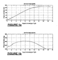
- Figures 1 a and 1b show the amplitude and phase distortion characteristics of a typical class AB power amplifier.
- Figure 1a gives the output signal envelope in volts as a function of the input signal envelope in volts, showing the characteristic amplitude compression as the amplifiers nears its saturated output power.
- Figure 1b gives the phase shift through the high power amplifier as a function of the input signal amplitude envelope.
- Figures 1c and 1d show the effect of amplifier distortion on a spread-spectrum modulated signal.
- Figure 1c shows the power spectrum of a 20 channel QPSK signal applied to the power amplifier input
- Figure 1d shows the resulting power spectrum at the amplifier output.
- the spectrum has developed sidebands , termed 'regrowth sidebands' which are characteristic of amplifier distortion. Regrowth sidebands are a system problem since they can potentially interfere with neighbouring communication channels. Specification limits on regrowth sidebands are therefore stringently specified in most cellular communication standards.
- Figure 1 2 shows a conventional cavity combiner transmitter system.
- a plurality of separate transmitters TX1, TX2....TXM each generate a signal which occupies a particular radio frequency band which is then amplified by respective high power amplifier HPA1, HPA2, whereasHPAN.
- HPA1, HPA2, ...HPAN The set of N such amplified signals are combined by a cavity combiner P10 for feeding to an antenna P15.
- a disadvantage of this is the expensive cavity combiner which typically needs to be adjustable in order to combine the power amplifiers with low loss, and maintain this low loss even in the event of an amplifier failure.
- FIG 3 shows an alternative transmitter architecture which is enabled by use of a linearised amplifier such as described in this document.
- Multiple transmitters on various channel frequencies are combined at a low signal level by a passive combiner (P20).
- the passive combiner (P20) does not need to be low loss and can therefore be an inexpensive hybrid type.
- Such a passive combiner also maintains high isolation between its input ports in the event of a fault on one of its inputs.
- the combined output being a composite of modulated signals at different channel frequencies, is then applied to a linearised high power amplifier (P25) such as that described in this document.
- P25 linearised high power amplifier
- the multi-carrier signal is amplified without generating unacceptable intermodulation products and is radiated from antenna (P15) via a low cost, low loss band filter (P30). .
- the amplifier arrangement does not cope with smaller numbers of signals effectively and reduces the error signals to around -20-30dbs.
- FIG. 4 shows a block diagram of a first embodiment made in accordance with the invention.
- an RF input signal (10) is applied to a high power amplifier (22) via a directional coupler (12), a first delay line (14), an amplitude modulator (16) and a phase modulator (18).
- An output of the amplifier (22) provides an amplified output signal (28) which is sampled by a directional coupler (26).
- the sampled RF output from the directional coupler (12) is applied to a power splitter (32), the outputs of which are connected to an envelope detector (34) and a second delay line (40).
- the output of the envelope detector is connected to an adaptive pre-distorter subsystem (70).
- the adaptive pre-distorter subsystem (70) generates two outputs: a gain correction signal (92) which is connected to the control port of first amplitude modulator (16); and a phase correction signal (94) which is connected to the control port of phase modulator (18).
- the adaptive pre-distorter (70) generates the correction signals (92, 94) as functions of input (36) in such a way that the input signal, delayed by (14) and modulated by modulators (16, 18), on passing through the high power amplifier (22) emerges with lower distortion than if no pre-distortion subsystem had been employed.
- the purpose of the pre-distorter gain and phase transfer functions is therefore to cancel the gain and phase distortion produced in the power amplifier (22).
- the purpose of delay line (14) is to compensate for any delay skew between the signal (10) modulation and the correction signals (92, 94) induced by processing delay in the correction path (12, 32, 34, 70).
- the error detection subsystem (60) requires as inputs a sample (42) of the input signal (10) and a sample (54) of the output signal (28), normalised to the same signal level and aligned in time.
- Output sample (54) is normalised to the same level as (42) by attenuating the coupled output of coupler (26) in attenuator (52); input sample (42) is time-aligned with (54) by delaying one output of power splitter (32) in delay line (40).
- the pre-distorter (70) operates on an adaptive basis. That is, the pre-distorter (70) adaptively adjusts its gain and phase transfer functions in response to residual gain error (82) and residual phase error (84) signals fed back from an error detection subsystem (60).
- the pre-distortion functions therefore optimally converge as the system operates.
- Figure 5 shows an implementation of error detection subsystem (60) as may be used in the above described amplifier.
- the input signals (42) and (54) are each split by power splitters (602) and (604) respectively.
- An output of splitter (602) is fed to envelope detector (610) and an output of splitter (604) is fed to envelope detector (612).
- the envelope detectors (610, 612) produce output voltages proportional to the amplitude envelope of signals (42) and (54) respectively.
- the output voltage of detector (610) is subtracted from the output of detector (612) by a differential amplifier (616) to produce a signal (618) proportional to the amplitude error between (42) and (54).
- the difference signal (618) is divided in analogue divider block (620) by signal (614) being the output of envelope detector (610) to produce a signal (82) which is proportional to the gain error between (42) and (54).
- the gain error signal (82) is a metric only of the gain distortion (amplitude compression or expansion) in the power amplifier and is independent of the input signal envelope level. This can improve the stability of the amplitude adaptation loop allowing parameter ⁇ g to be set more closely for rapid conversions.
- phase comparator (630) which has two outputs (632) and (634). If the RF input from splitter (602) is represented in polar form by R 1 .cos( ⁇ c t + ⁇ ) and the RF input from splitter (604) is represented by R 2 .cos( ⁇ c t + ⁇ ) then the response of phase comparator (630) is such that output (632) is proportional to R 1 .R 2 .cos( ⁇ - ⁇ ) and output (634) is proportional to R 1 .R 2 .sin( ⁇ - ⁇ ).
- Analogue divider block (636) divides output (634) by (632) to give phase error signal (84): it should be noted that this divider is merely correcting for the amplitude response of the differential phase detector and hence performs a different role to that (620) in the gain error loop. Phase error signal (84) is then equal to tan( ⁇ - ⁇ ) which for ( ⁇ - ⁇ ) small is approximately proportional to ( ⁇ - ⁇ ).
- error detector (60) Variations of the error detector (60) are possible. Depending on the performance required, the amplitude analogue divider (620) may be omitted (although ⁇ g will need to be set to a lower value in order to preserve a loop stability), an alternative configuration of amplitude detectors and signal processing elements may be used. Alternative types of phase discriminator may also be used. A variation of the error detector (60) may be implemented which generates error signals (82, 84) relating to the signs of the amplitude and phase errors only, as are commonly employed elsewhere in the field of control systems.
- the error detection block (60) may be partially or entirely replaced by digital implementation, wherein the RF signals (42, 54) are digitised and the error signals (82, 84) are computed by digital signal processing means (DSP). The feeding of these error signals to gain blocks (724, 754) into the predistorter (70) can then be performed in the digital domain.
- DSP digital signal processing means
- Figure 6 shows an implementation of the adaptive digital pre-distorter (70).
- Signal (36) being proportional to the amplitude envelope of the system input (10) is filtered by a low-pass anti-alias filter (702) and is digitised by (704), an analogue-to-digital converter.
- the m-bit output of the ADC is connected to the m bits of an address bus (760) via a multiplexer (706).
- the address bus (760) is used to select an address in RAM (710) a 2 m word phase correction random access memory (RAM) and (740), a 2 m word gain correction RAM.
- phase correction RAM (710) The data bus (713) of phase correction RAM (710) is connected to (712), a latching digital-to-analogue converter (DAC).
- the output of the DAC (712) is filtered by a low-pass anti-alias filter (714) to give phase correction signal (94).
- the data bus (743) of gain correction RAM (740) is connected to latching DAC (742).
- the output of DAC (742) is filtered by low-pass anti-alias filter (744) to give gain correction signal (92).
- phase correction RAM (710) asserts a correction value on its data bus (713) which is converted to an analogue phase correction signal (94) via DAC (712) and filter (714), which in the first embodiment is low-pass and band-pass in the second embodiment, as will become apparent.
- gain correction RAM (740) asserts a correction value on its data bus (743) which is converted to an analogue gain correction signal (92) via DAC (742) and filter (744). In this way the gain and phase correction signals required by the system are generated during clock phase one.
- FIFO first-in-first-out
- the contents of the correction RAMs (710, 740) are set into write mode via their read-write inputs (762, 764) and their contents are adapted.
- the residual phase error signal (84) is filtered by anti-alias filter (720) and digitised by ADC (722).
- the result is multiplied by a fixed coefficient ⁇ p in (724)and is applied to a subtractor (726).
- the subtractor forms the difference between the output of FIFO (716) and the output of (724).
- the resulting digital signal (727) is applied to the phase RAM data bus (713) via a 3-state buffer (728) which passes data on phase two but isolates it on phase one of the clock.
- the residual gain error signal (82) is filtered by anti-alias filter (750) and digitised by ADC (752).
- the result is multiplied by a fixed coefficient ⁇ 9 in (754) and is applied to a subtractor (756).
- the subtractor forms the difference between the output of FIFO (746) and the output of (754).
- the resulting digital signal (757) is applied to the phase RAM data bus (743) via a 3-state buffer (758) which passes data on phase two but isolates it on phase one of the clock.
- the settings of convergence parameters ⁇ p and ⁇ g are adjusted to achieve the desired convergence speed whilst maintaining system stability.
- multiplexer (706) switches to pass data from FIFO (708) to address bus (760). If the delay in FIFOs (708, 716) and (746) is k cycles of the pre-distorter clock then on clock phase two the address bus (760) is thereby set to select the entries in RAMs (710, 740) corresponding to the signal envelope k clock cycles ago. At the same time, the output of FIFO (716) corresponds to the phase correction value which was used k clock cycles ago. The output of (724) constitutes a metric of the residual phase error left at the same instant (k clock cycles ago) when this phase correction was applied, assuming the FIFO delays have been adjusted correctly.
- the output of subtractor (726) represents an improved estimate of the phase correction factor needed for the signal envelope value currently asserted on address bus (760).
- the write enable control of phase correction RAM (710) is strobed, thereby writing the improved estimate (727) into the correct location of the RAM.
- FIFO (746) yields, on clock phase two, the gain correction factor applied k cycles previously.
- Subtractor (756) forms an improved estimate of the correction factor needed for the envelope value asserted on address bus (760) by subtracting the scaled residual gain error at the output of (754) from the FIFO (746) output.
- the write enable control of gain correction RAM (740) is strobed, thereby writing the improved estimate (757) into the correct location of the RAM.
- the architecture provides a method whereby the LUT adaptively 'learns' the pre-distortion coefficients required.
- the input and output signals of the system are sampled. It is preferable that the input signal is delayed and the output signal attenuated so that the sampled signals are equal in power and any skew in the modulation envelope is resolved. Such delay and attenuation may be intrinsically associated with the circuitry, but it is preferable that dedicated circuit components are provided whereby the power and skew between the input signal at the gain and phase detector may be controlled.
- the two signals are each split into two: one output being fed into a gain error detector and the other being fed into a phase error detector.
- the gain error detector produces an output approximately proportional to the gain error between the signals
- the phase error detector produces an output approximately proportional to the phase error between the signals.
- the gain and phase error signals are digitised by an anti-alias filter and ADC.
- the input envelope samples and gain and phase correction samples are delayed in first-in-first-out (FIFO) buffer memory to align them in timing with the sampled error signals from the gain and phase error detectors.
- the gain and phase error signals are multiplied by a fixed fractional convergence parameter and are subtracted from the delayed gain and phase correction signals respectively to obtain signals which are an improved estimate of what the correction signals at the stored signal envelope should have been.
- the improved gain and phase correction estimates are written back, sample by sample, into the lookup table using the delayed envelope signal to determine the correct addresses, thereby improving the accuracy of the pre-distortion in future.
- the method of adaptation described above modifies one look-up table entry corresponding to one quantised envelope value for each sample of the gain and phase error signals. Hence each entry of the look-up table converges independently of the others. While having a large number of independent table entries has the benefit of being able to adapt to the wider strain of AM-AM and AM-PM functions, it can be disadvantageous with respect to convergence speed and estimation error.
- Variations of the algorithm are possible where the use of a single sample of the gain and phase error signals are used to modify multiple adjacent look-up table entries, using a primary knowledge of the properties of the look-up table function, such as limits in the rate of change of amplifier distortion with amplitude that are known for the amplifier employed.
- one such variation consists of the steps of: taking an off-line copy of the current gain and phase look-up tables; adapting one or more entries according to the basic algorithm; filtering using a low-pass filter the off-line gain and phase tables with respect to envelope value index; and, writing the modified tables back into the predistorter.
- the pre-distorter will adapt to track out changes in gain and phase response of the high power amplifier (22) and no further control systems are needed.
- the proposed architecture performs adaptive pre-distortion of x c (t) in the polar domain by the following steps:
- Figure 7 shows a block diagram of the second embodiment of the invention, wherein the system includes second amplitude (20) and second phase (21) modulators and baseband processing elements (86, 87, 88, 89). These form slow feedback loops operating in the gain and phase domains in order to centre the operation of the pre-distorter and allow system components of greatly reduced operating range to be used.
- second amplitude (20) and second phase (21) modulators and baseband processing elements 86, 87, 88, 89.
- the gain error signal (82) is integrated by integrator (88) and amplified by gain block (89). It is then applied to a second amplitude modulator (20) which adjusts the signal level into the second phase modulator (21) and high power amplifier (22).
- the arrangement forms a control loop with integral action whereby the output level is adjusted to set the sampled output (52) at the same average envelope voltage as the sampled input (42).
- the operation of the slow phase feedback loop is as follows: the phase error signal (84) is integrated by integrator (86) and amplified by gain block (87). It is then applied to a slow phase modulator (21) which adjusts the phase of the signal into the high power amplifier (22).
- the arrangement forms a control loop with integral action whereby the average phase of the sampled output (52) is adjusted to the same average phase as the sampled input (42).
- the correction signal anti-alias filters (714) and (744) have a zero at DC (i.e. are AC coupled) in order to prevent the pre-distorter adaptation and slow loop adjustments interacting.
- the sampled RF output from directional coupler (12) is applied to a power splitter (32), the outputs of which are connected to an envelope detector (34) and a delay line (40).
- the output of the envelope detector is connected to an adaptive pre-distorter subsystem (70).
- the adaptive pre-distorter subsystem (70) generates two outputs: a gain correction signal (92) which is connected to the control port of first amplitude modulator (16); and a phase correction signal (94) which is connected to the control port of first phase modulator (18).
- the pre-distorter (70) adaptively adjusts its gain and phase transfer functions in response to residual gain error (82) and residual phase error (84) signals fed back from an error detection subsystem (60) and the error detection subsystem (60) operates as described above.
- the 'slow feedback' control system nulls out the average gain and phase errors in the adaptation loop.
- the output of the gain error detector mentioned above is integrated and amplified to provide a control signal which modulates a gain control element between the pre-distorter and the power amplifier itself.
- the output of the phase error detector mentioned above is integrated and amplified to provide a control signal which modulates a phase control element between the pre-distorter and the power amplifier.
- the present invention provides a completely polar-domain design which is capable of providing pre-distortion to a standalone radio frequency power amplifier rather than being necessarily being incorporated into an existing DSP system.
- the analogue signal processing used to condition error signal and provide input signals eliminates the need to accurately digitise wideband signals at the carrier frequency in order to drive DSP implementations of the error feedback system and pre-distorter.
- the correction signals from the pre-distorter are applied to the input signal via analogue radio frequency control elements whereby at no stage is the input signal to the power amplifier required to be in the digital domain.
- slow loops can be used to stabilise the power amplifier gain and phase response, thereby reducing the dynamic range required from the pre-distorter look-up table. This is of advantage for many applications such as in the provision of high power linear amplifiers in the transmission of signals in cellular radio base stations.
Landscapes
- Physics & Mathematics (AREA)
- Nonlinear Science (AREA)
- Engineering & Computer Science (AREA)
- Power Engineering (AREA)
- Amplifiers (AREA)
- Transmitters (AREA)
- Tone Control, Compression And Expansion, Limiting Amplitude (AREA)
- Digital Transmission Methods That Use Modulated Carrier Waves (AREA)
Applications Claiming Priority (2)
| Application Number | Priority Date | Filing Date | Title |
|---|---|---|---|
| US209386 | 1998-12-10 | ||
| US09/209,386 US6275685B1 (en) | 1998-12-10 | 1998-12-10 | Linear amplifier arrangement |
Publications (2)
| Publication Number | Publication Date |
|---|---|
| EP1011192A2 true EP1011192A2 (de) | 2000-06-21 |
| EP1011192A3 EP1011192A3 (de) | 2002-05-15 |
Family
ID=22778564
Family Applications (1)
| Application Number | Title | Priority Date | Filing Date |
|---|---|---|---|
| EP99203954A Withdrawn EP1011192A3 (de) | 1998-12-10 | 1999-11-24 | Lineare Verstärkeranordnung |
Country Status (4)
| Country | Link |
|---|---|
| US (1) | US6275685B1 (de) |
| EP (1) | EP1011192A3 (de) |
| JP (1) | JP2000216640A (de) |
| CA (1) | CA2291863C (de) |
Cited By (29)
| Publication number | Priority date | Publication date | Assignee | Title |
|---|---|---|---|---|
| JP2002026665A (ja) * | 2000-07-07 | 2002-01-25 | Sony Corp | 歪補償装置および歪補償方法 |
| WO2002011379A1 (fr) * | 2000-07-20 | 2002-02-07 | Huawei Technologies Co., Ltd. | Procede et appareil de predistorsion numerique auto-adaptatif d'un emetteur sans fil |
| GB2376584A (en) * | 2001-06-15 | 2002-12-18 | Wireless Systems Int Ltd | An adaptive predistorter using normalised errors |
| GB2376613A (en) * | 2001-06-15 | 2002-12-18 | Wireless Systems Int Ltd | Signal distortion correction using predistortion |
| EP1276243A1 (de) * | 2001-07-11 | 2003-01-15 | TTPCOM Limited | Sender für Mobiles Telekommunikationsendgerät |
| WO2003003683A3 (de) * | 2001-06-27 | 2003-04-03 | Deutsche Telekom Ag | Verfahren zur vermeidung von störausstrahlungen bei am-sendern für digitale übertragung |
| EP1067696A3 (de) * | 1999-07-09 | 2003-11-12 | Sony Corporation | Verzerrungsausgleichverfahren und drahtloses Kommunikationsgerät |
| GB2354126B (en) * | 1999-09-13 | 2004-07-21 | Wireless Systems Int Ltd | Signal processing |
| EP1193865A3 (de) * | 2000-09-29 | 2005-02-09 | Sony Corporation | Verzerrungsskompensationseinrichtung und Verfahren |
| EP1511181A4 (de) * | 2002-05-31 | 2005-07-27 | Fujitsu Ltd | Verzerrungskompensator |
| EP1742351A1 (de) * | 2005-07-07 | 2007-01-10 | Hitachi Kokusai Electric Inc. | Vorverzerrungsverstärker |
| EP1335489A4 (de) * | 2000-09-19 | 2007-03-28 | Japan Science & Tech Corp | Leistungsverstärker mit kompensation nichtlinearer verzerrungen |
| KR100768102B1 (ko) | 2005-12-08 | 2007-10-17 | 한국전자통신연구원 | 직접 시퀀스 대역 확산 방식의 무선 피코셀 통신시스템에서의 위상 추적 장치 및 그 방법 |
| EP1865677A1 (de) * | 2006-06-06 | 2007-12-12 | Fujitsu Limited | Vorrichtung und Verfahren zur Frequenzbereich-Vorverzerrung in einem drahtlosen Übertragungssystem |
| US7330073B2 (en) | 2004-10-06 | 2008-02-12 | Telefonaktiebolaget L M Ericsson (Publ) | Arbitrary waveform predistortion table generation |
| US7362818B1 (en) | 2001-08-30 | 2008-04-22 | Nortel Networks Limited | Amplitude and phase comparator for microwave power amplifier |
| WO2008140730A1 (en) | 2007-05-10 | 2008-11-20 | M/A-Com, Inc. | Linear rf amplifier with polar feedback |
| US7746955B2 (en) | 2003-03-25 | 2010-06-29 | Telefonaktiebolaget Lm Ericsson (Publ) | Power amplifier pre-distortion |
| US7848716B2 (en) | 2005-02-28 | 2010-12-07 | Renesas Electronics Corporation | Semiconductor integrated circuit for communication |
| KR101006965B1 (ko) * | 2010-01-22 | 2011-01-12 | (주)앤트테크놀로지 | 선형화 기술을 이용한 대전력 증폭기 |
| WO2012003408A1 (en) * | 2010-06-30 | 2012-01-05 | Qualcomm Incorporated | Predistortion of complex modulated waveform |
| CN102882478A (zh) * | 2011-07-15 | 2013-01-16 | 瑞昱半导体股份有限公司 | 功率放大器的补偿装置及其相关方法 |
| US8594159B2 (en) | 2007-09-26 | 2013-11-26 | Fujitsu Limited | Transceiver amplifier and delay deviation compensation method |
| CN104348428A (zh) * | 2013-07-23 | 2015-02-11 | 晨星半导体股份有限公司 | 用于振幅调变至相位调变失真补偿的装置及方法 |
| US8964821B2 (en) | 2011-10-14 | 2015-02-24 | Qualcomm Incorporated | Shared feedback for adaptive transmitter pre-distortion |
| CN110266276A (zh) * | 2019-05-17 | 2019-09-20 | 杭州电子科技大学 | 5g超宽带功率放大器低速数字预失真方法 |
| WO2021259448A1 (en) * | 2020-06-22 | 2021-12-30 | Telefonaktiebolaget Lm Ericsson (Publ) | Transmitter circuit |
| US11990875B2 (en) | 2019-01-10 | 2024-05-21 | Telefonaktiebolaget Lm Ericsson (Publ) | Bias circuit and power amplifier circuit |
| US12381525B2 (en) * | 2022-06-28 | 2025-08-05 | Qorvo Us, Inc. | Amplifier system |
Families Citing this family (173)
| Publication number | Priority date | Publication date | Assignee | Title |
|---|---|---|---|---|
| KR100264789B1 (ko) * | 1998-06-16 | 2000-09-01 | 김영환 | 이동통신 시스템의 기지국 송신기 입력 및 출력 레벨 측정장치 |
| SE513156C2 (sv) * | 1998-07-10 | 2000-07-17 | Ericsson Telefon Ab L M | Anordning och förfarande relaterande till radiokommunikation |
| BR9816112A (pt) * | 1998-12-24 | 2001-09-04 | Nokia Networks Oy | Transmissor de portador de múltiplas frequências, estação base, e, método de transmissão de frequência de múltiplos portadores |
| US6748026B1 (en) * | 1999-02-12 | 2004-06-08 | Matsushita Electric Industrial Co., Ltd. | Distortion estimation apparatus, frequency offset compensation apparatus and reception apparatus |
| JP3709316B2 (ja) * | 1999-05-28 | 2005-10-26 | 松下電器産業株式会社 | 通信装置及び通信方法 |
| DE19927952A1 (de) * | 1999-06-18 | 2001-01-04 | Fraunhofer Ges Forschung | Vorrichtung und Verfahren zum Vorverzerren eines über eine nicht-lineare Übertragungsstrecke zu übertragenden Übertragungssignals |
| US6697436B1 (en) | 1999-07-13 | 2004-02-24 | Pmc-Sierra, Inc. | Transmission antenna array system with predistortion |
| US6798843B1 (en) * | 1999-07-13 | 2004-09-28 | Pmc-Sierra, Inc. | Wideband digital predistortion linearizer for nonlinear amplifiers |
| US6693974B2 (en) * | 1999-08-05 | 2004-02-17 | Samsung Electronics Co., Ltd. | Adaptive digital pre-distortion circuit using adjacent channel power profile and method of operation |
| US6356742B1 (en) * | 1999-08-30 | 2002-03-12 | Thomcast Communications, Inc. | Adaptive precorrection of signal combiners using passive hybrid junction sample cancellation |
| US6246286B1 (en) * | 1999-10-26 | 2001-06-12 | Telefonaktiebolaget Lm Ericsson | Adaptive linearization of power amplifiers |
| CA2329100A1 (en) * | 1999-12-21 | 2001-06-21 | Nortel Networks Limited | Phase and amplitude detector and method of determining errors |
| US6751447B1 (en) * | 1999-12-30 | 2004-06-15 | Samsung Electronics Cop., Ltd. | Adaptive digital pre-distortion circuit using output reference signal and method of operation |
| WO2001052442A1 (en) * | 2000-01-10 | 2001-07-19 | Airnet Communications Corporation | Method and apparatus for equalization in transmit and receive levels in a broadband transceiver system |
| US6831954B1 (en) * | 2000-02-01 | 2004-12-14 | Nokia Corporation | Apparatus, and associated method, for compensating for distortion introduced upon a send signal by an amplifier |
| GB0011326D0 (en) * | 2000-05-11 | 2000-06-28 | Nortel Networks Corp | A linear amplifier arrangement |
| US6489846B2 (en) * | 2000-05-25 | 2002-12-03 | Sony Corporation | Distortion compensating device and distortion compensating method |
| JP4326673B2 (ja) * | 2000-06-06 | 2009-09-09 | 富士通株式会社 | 非線形歪補償装置を有する通信装置の起動方法 |
| JP2002009556A (ja) * | 2000-06-16 | 2002-01-11 | Sony Corp | 歪補償装置及び歪補償方法 |
| US6707857B1 (en) * | 2000-07-14 | 2004-03-16 | Ericsson Inc. | Reference signal pre-distortion for transmitter with frequency synthesizer based phase encoding |
| US6650875B1 (en) * | 2000-08-30 | 2003-11-18 | Skyworks Solutions, Inc. | Transmitter architecture having a secondary phase-error correction loop including an amplitude reconstruction system |
| JP3590571B2 (ja) | 2000-08-30 | 2004-11-17 | 株式会社日立国際電気 | 歪補償装置 |
| KR100374828B1 (ko) * | 2000-09-15 | 2003-03-04 | 엘지전자 주식회사 | 적응성 전치왜곡 송신기 |
| JP2002111398A (ja) * | 2000-09-29 | 2002-04-12 | Sony Corp | 歪補償装置及び歪補償方法 |
| US6987954B2 (en) * | 2001-05-15 | 2006-01-17 | Research In Motion Limited | Feedback compensation detector for a direct conversion transmitter |
| GB2376583B (en) * | 2001-06-15 | 2005-01-05 | Wireless Systems Int Ltd | Time alignment of signals |
| US7409004B2 (en) * | 2001-06-19 | 2008-08-05 | Matsushita Electric Industrial Co., Ltd. | Hybrid polar modulator differential phase Cartesian feedback correction circuit for power amplifier linearization |
| US6600374B2 (en) * | 2001-06-25 | 2003-07-29 | Rambus Inc. | Collective automatic gain control |
| US7203247B2 (en) * | 2001-07-23 | 2007-04-10 | Agere Systems Inc. | Digital predistortion technique for WCDMA wireless communication system and method of operation thereof |
| US6731694B2 (en) | 2001-08-07 | 2004-05-04 | Motorola, Inc. | Isolator eliminator for a linear transmitter |
| US7382833B1 (en) * | 2001-08-16 | 2008-06-03 | Rockwell Collins, Inc. | System for phase, gain, and DC offset error correction for a quadrature modulator |
| US8107901B2 (en) * | 2001-08-20 | 2012-01-31 | Motorola Solutions, Inc. | Feedback loop with adjustable bandwidth |
| KR100438844B1 (ko) * | 2001-11-08 | 2004-07-05 | 주식회사 씨원테크놀로지 | 아이엠디 특성 제어와 감시를 위하여 전력증폭기 내부에내장된 스펙트럼 분석기와 지유아이 |
| US7058369B1 (en) * | 2001-11-21 | 2006-06-06 | Pmc-Sierra Inc. | Constant gain digital predistortion controller for linearization of non-linear amplifiers |
| US6947712B2 (en) * | 2001-12-12 | 2005-09-20 | Agere Systems Inc. | Group delay precompensator for broadband radio frequency transmitter and method of operating the same |
| US6703897B2 (en) * | 2001-12-26 | 2004-03-09 | Nortel Networks Limited | Methods of optimising power amplifier efficiency and closed-loop power amplifier controllers |
| US7085330B1 (en) | 2002-02-15 | 2006-08-01 | Marvell International Ltd. | Method and apparatus for amplifier linearization using adaptive predistortion |
| US7362821B1 (en) | 2002-05-22 | 2008-04-22 | Marvel International Ltd. | Method and apparatus for amplifier linearization using adaptive predistortion |
| AU2003213930A1 (en) * | 2002-03-26 | 2003-10-08 | Her Majesty In Right Of Canada As Represented By The Minister Of Industry | Adaptive predistorter based on the probability distribution function of the output amplitude |
| JP3874688B2 (ja) * | 2002-03-29 | 2007-01-31 | 富士通株式会社 | 歪補償装置 |
| US6985704B2 (en) | 2002-05-01 | 2006-01-10 | Dali Yang | System and method for digital memorized predistortion for wireless communication |
| US8472897B1 (en) | 2006-12-22 | 2013-06-25 | Dali Systems Co. Ltd. | Power amplifier predistortion methods and apparatus |
| US8811917B2 (en) | 2002-05-01 | 2014-08-19 | Dali Systems Co. Ltd. | Digital hybrid mode power amplifier system |
| US8380143B2 (en) | 2002-05-01 | 2013-02-19 | Dali Systems Co. Ltd | Power amplifier time-delay invariant predistortion methods and apparatus |
| US7991071B2 (en) * | 2002-05-16 | 2011-08-02 | Rf Micro Devices, Inc. | AM to PM correction system for polar modulator |
| US7801244B2 (en) * | 2002-05-16 | 2010-09-21 | Rf Micro Devices, Inc. | Am to AM correction system for polar modulator |
| GB2412512B (en) * | 2002-05-31 | 2005-11-16 | Renesas Tech Corp | A communication semiconductor integrated circuit, a wireless communication apparatus, and a loop gain calibration method |
| DE60238508D1 (de) * | 2002-05-31 | 2011-01-13 | Fujitsu Ltd | Verzerrungskompensationsvorrichtung |
| US7551905B2 (en) * | 2002-05-31 | 2009-06-23 | Fujitsu Limited | Distortion compensation apparatus |
| JP2004040564A (ja) * | 2002-07-04 | 2004-02-05 | Fujitsu Ltd | 電力増幅器の歪補償方法及びその装置 |
| US7149484B2 (en) * | 2002-10-03 | 2006-12-12 | Intel Corporation | Portable communication device having adjustable amplification and method therefor |
| JP3985649B2 (ja) * | 2002-10-03 | 2007-10-03 | 松下電器産業株式会社 | 送信方法及び送信装置 |
| US7254195B2 (en) * | 2003-08-25 | 2007-08-07 | M/A-Com, Inc. | Apparatus, methods and articles of manufacture for dynamic differential delay correction |
| DE10247034B3 (de) * | 2002-10-09 | 2004-02-19 | Siemens Ag | Verfahren zur adaptiven Vorverzerrung digitaler Rohdatenwerte und Vorrichtung zu dessen Durchführung |
| US7349365B2 (en) * | 2002-10-22 | 2008-03-25 | Mitsubishi Electric Research Laboratories, Inc. | Mobile telephone messaging by baseband envelope modulation |
| US7277678B2 (en) * | 2002-10-28 | 2007-10-02 | Skyworks Solutions, Inc. | Fast closed-loop power control for non-constant envelope modulation |
| US7333557B2 (en) * | 2002-12-16 | 2008-02-19 | Nortel Networks Limited | Adaptive controller for linearization of transmitter with impairments |
| US7403573B2 (en) * | 2003-01-15 | 2008-07-22 | Andrew Corporation | Uncorrelated adaptive predistorter |
| US7627055B2 (en) * | 2003-02-27 | 2009-12-01 | Nokia Corporation | Error adjustment in direct conversion architectures |
| US7295819B2 (en) * | 2003-03-11 | 2007-11-13 | Andrew Corporation | Signal sample acquisition techniques |
| US7123890B2 (en) * | 2003-03-11 | 2006-10-17 | Andrew Corporation | Signal sample acquisition techniques |
| JP4716306B2 (ja) * | 2003-03-24 | 2011-07-06 | 三菱電機株式会社 | プレディストータ |
| US7729668B2 (en) | 2003-04-03 | 2010-06-01 | Andrew Llc | Independence between paths that predistort for memory and memory-less distortion in power amplifiers |
| US7127020B2 (en) * | 2003-05-09 | 2006-10-24 | Texas Instruments Incorporated | Frequency synthesis loop having controlled loop gain |
| US6972622B2 (en) | 2003-05-12 | 2005-12-06 | Andrew Corporation | Optimization of error loops in distributed power amplifiers |
| US7149257B2 (en) * | 2003-07-03 | 2006-12-12 | Powerwave Technologies, Inc. | Digital predistortion system and method for correcting memory effects within an RF power amplifier |
| US7259630B2 (en) * | 2003-07-23 | 2007-08-21 | Andrew Corporation | Elimination of peak clipping and improved efficiency for RF power amplifiers with a predistorter |
| US6963242B2 (en) * | 2003-07-31 | 2005-11-08 | Andrew Corporation | Predistorter for phase modulated signals with low peak to average ratios |
| US6882221B2 (en) * | 2003-09-22 | 2005-04-19 | Northrop Grumman Corporation | Digital predistortion for power amplifier |
| US7023273B2 (en) * | 2003-10-06 | 2006-04-04 | Andrew Corporation | Architecture and implementation methods of digital predistortion circuitry |
| US7146138B2 (en) * | 2003-10-21 | 2006-12-05 | Kiomars Anvari | Power boosting technique for wireless multi-carrier power amplifier |
| KR20050069152A (ko) * | 2003-12-31 | 2005-07-05 | 동부아남반도체 주식회사 | 횡형 디모스 트랜지스터 소자 |
| JP4323968B2 (ja) * | 2004-01-14 | 2009-09-02 | 株式会社日立コミュニケーションテクノロジー | 無線通信装置のタイミング調整方法 |
| WO2005076495A1 (en) * | 2004-02-09 | 2005-08-18 | Sige Semiconductor Inc. | Methods of enhancing power amplifier linearity |
| US6998909B1 (en) * | 2004-02-17 | 2006-02-14 | Altera Corporation | Method to compensate for memory effect in lookup table based digital predistorters |
| US7250815B2 (en) * | 2004-02-25 | 2007-07-31 | Intel Corporation | Amplifier distortion management apparatus, systems, and methods |
| US7113036B2 (en) * | 2004-04-15 | 2006-09-26 | Agere Systems Inc. | Method and apparatus for adaptive digital predistortion using nonlinear and feedback gain parameters |
| US7551686B1 (en) * | 2004-06-23 | 2009-06-23 | Rf Micro Devices, Inc. | Multiple polynomial digital predistortion |
| JP4868319B2 (ja) * | 2004-07-29 | 2012-02-01 | エスティー‐エリクソン、ソシエテ、アノニム | 位相および/または振幅変調信号のための複合信号スケーリング |
| US7529523B1 (en) | 2004-08-23 | 2009-05-05 | Rf Micro Devices, Inc. | N-th order curve fit for power calibration in a mobile terminal |
| EP1835626B1 (de) * | 2005-01-04 | 2010-12-15 | Fujitsu Ltd. | Gleichstrom-offsetkompensationsverfahren und -einrichtung |
| DE102005013881A1 (de) * | 2005-03-24 | 2006-09-28 | Infineon Technologies Ag | Verfahren zur Signalverarbeitung und Sendeeinrichtung mit digitaler Vorverzerrung, insbesondere für den Mobilfunk |
| DE102005013880B3 (de) * | 2005-03-24 | 2006-04-20 | Infineon Technologies Ag | Verfahren zur Vorverzerrung eines Signals und Sendeeinrichtung mit digitaler Vorverzerrung, insbesondere für Mobilfunk |
| US8224265B1 (en) | 2005-06-13 | 2012-07-17 | Rf Micro Devices, Inc. | Method for optimizing AM/AM and AM/PM predistortion in a mobile terminal |
| US7653147B2 (en) * | 2005-08-17 | 2010-01-26 | Intel Corporation | Transmitter control |
| US7773695B2 (en) | 2005-08-19 | 2010-08-10 | Dominic Kotab | Amplitude modulator |
| US7769103B2 (en) * | 2005-09-15 | 2010-08-03 | Powerwave Technologies, Inc. | Amplifier system employing analog polynomial predistortion with sub-nyquist digital adaptation |
| US7680176B2 (en) * | 2005-11-21 | 2010-03-16 | Telefonaktiebolaget Lm Ericsson (Publ) | Simplified generalized rake receiver method and apparatus |
| US8207777B1 (en) * | 2005-11-21 | 2012-06-26 | Analog Devices, Inc. | Compensation with ratiometric attenuation |
| US7869542B2 (en) * | 2006-02-03 | 2011-01-11 | Quantance, Inc. | Phase error de-glitching circuit and method of operating |
| US7917106B2 (en) * | 2006-02-03 | 2011-03-29 | Quantance, Inc. | RF power amplifier controller circuit including calibrated phase control loop |
| US7933570B2 (en) * | 2006-02-03 | 2011-04-26 | Quantance, Inc. | Power amplifier controller circuit |
| US8032097B2 (en) | 2006-02-03 | 2011-10-04 | Quantance, Inc. | Amplitude error de-glitching circuit and method of operating |
| CN101401261B (zh) * | 2006-02-03 | 2012-11-21 | 匡坦斯公司 | 功率放大器控制器电路 |
| US8095090B2 (en) * | 2006-02-03 | 2012-01-10 | Quantance, Inc. | RF power amplifier controller circuit |
| US7761065B2 (en) * | 2006-02-03 | 2010-07-20 | Quantance, Inc. | RF power amplifier controller circuit with compensation for output impedance mismatch |
| US7877060B1 (en) | 2006-02-06 | 2011-01-25 | Rf Micro Devices, Inc. | Fast calibration of AM/PM pre-distortion |
| US20070223621A1 (en) * | 2006-03-21 | 2007-09-27 | M/A-Com, Inc. | Method and apparatus for signal power ramp-up in a communication transmission |
| US7962108B1 (en) | 2006-03-29 | 2011-06-14 | Rf Micro Devices, Inc. | Adaptive AM/PM compensation |
| US7796960B1 (en) * | 2006-04-04 | 2010-09-14 | Nortel Networks Limited | Signal transmitter linearization |
| US8886341B1 (en) | 2006-04-04 | 2014-11-11 | Microsoft Corporation | Adaptive sample-by-sample controller for under-determined systems |
| US8995502B1 (en) * | 2006-04-04 | 2015-03-31 | Apple Inc. | Transceiver with spectral analysis |
| US8498590B1 (en) * | 2006-04-04 | 2013-07-30 | Apple Inc. | Signal transmitter linearization |
| CN101479956B (zh) * | 2006-04-28 | 2013-07-31 | 大力系统有限公司 | 用于无线通信的高效率线性化功率放大器 |
| US7844014B2 (en) * | 2006-07-07 | 2010-11-30 | Scintera Networks, Inc. | Pre-distortion apparatus |
| US7962174B2 (en) * | 2006-07-12 | 2011-06-14 | Andrew Llc | Transceiver architecture and method for wireless base-stations |
| US7689182B1 (en) | 2006-10-12 | 2010-03-30 | Rf Micro Devices, Inc. | Temperature compensated bias for AM/PM improvement |
| US8269543B2 (en) * | 2006-10-23 | 2012-09-18 | Teetzel Andrew M | Automatic RC/CR quadrature network |
| US8411709B1 (en) | 2006-11-27 | 2013-04-02 | Marvell International Ltd. | Use of previously buffered state information to decode in an hybrid automatic repeat request (H-ARQ) transmission mode |
| US7778352B2 (en) * | 2006-12-21 | 2010-08-17 | Broadcom Corporation | Digital compensation for nonlinearities in a polar transmitter |
| US9026067B2 (en) * | 2007-04-23 | 2015-05-05 | Dali Systems Co. Ltd. | Remotely reconfigurable power amplifier system and method |
| CN104202279A (zh) | 2006-12-26 | 2014-12-10 | 大力系统有限公司 | 用于多信道宽带通信系统中的基带预失真线性化的方法和系统 |
| US8009762B1 (en) | 2007-04-17 | 2011-08-30 | Rf Micro Devices, Inc. | Method for calibrating a phase distortion compensated polar modulated radio frequency transmitter |
| KR101484796B1 (ko) * | 2007-04-23 | 2015-01-20 | 달리 시스템즈 씨오. 엘티디. | N-웨이 도허티 분산형 전력 증폭기 |
| US8274332B2 (en) | 2007-04-23 | 2012-09-25 | Dali Systems Co. Ltd. | N-way Doherty distributed power amplifier with power tracking |
| US8068574B2 (en) * | 2007-05-31 | 2011-11-29 | Freescale Semiconductor, Inc. | Systems, apparatus, and methods for performing digital pre-distortion with feedback signal adjustment |
| US8224266B2 (en) * | 2007-08-30 | 2012-07-17 | Dali Systems Co., Ltd. | Power amplifier predistortion methods and apparatus using envelope and phase detector |
| US8897393B1 (en) | 2007-10-16 | 2014-11-25 | Marvell International Ltd. | Protected codebook selection at receiver for transmit beamforming |
| US8542725B1 (en) | 2007-11-14 | 2013-09-24 | Marvell International Ltd. | Decision feedback equalization for signals having unequally distributed patterns |
| US8213883B1 (en) * | 2007-12-04 | 2012-07-03 | Scintera Networks, Inc. | Additive pre-distortion for linearization |
| KR101669173B1 (ko) * | 2007-12-07 | 2016-10-25 | 달리 시스템즈 씨오. 엘티디. | 베이스밴드-도출형 광대역 rf 디지털 전치 왜곡 시스템 |
| US20090146784A1 (en) * | 2007-12-10 | 2009-06-11 | Mohammad Soleimani | Method and System for Variable Power Amplifier Bias in RFID Transceivers |
| US8081935B2 (en) * | 2008-01-08 | 2011-12-20 | Panasonic Corporation | Multiple-mode modulator to process baseband signals |
| US8565325B1 (en) | 2008-03-18 | 2013-10-22 | Marvell International Ltd. | Wireless device communication in the 60GHz band |
| US8761261B1 (en) | 2008-07-29 | 2014-06-24 | Marvell International Ltd. | Encoding using motion vectors |
| US8498342B1 (en) | 2008-07-29 | 2013-07-30 | Marvell International Ltd. | Deblocking filtering |
| CN102113221A (zh) * | 2008-08-05 | 2011-06-29 | 富士通株式会社 | 发送装置以及调整值测定方法 |
| US8345533B1 (en) | 2008-08-18 | 2013-01-01 | Marvell International Ltd. | Frame synchronization techniques |
| US8681893B1 (en) | 2008-10-08 | 2014-03-25 | Marvell International Ltd. | Generating pulses using a look-up table |
| US8706062B1 (en) | 2008-12-19 | 2014-04-22 | Scintera Networks, Inc. | Self-adaptive power amplification |
| WO2010073483A1 (ja) * | 2008-12-22 | 2010-07-01 | 株式会社日立国際電気 | 歪補償増幅器 |
| US7777566B1 (en) * | 2009-02-05 | 2010-08-17 | Quantance, Inc. | Amplifier compression adjustment circuit |
| US20120032739A1 (en) * | 2009-03-09 | 2012-02-09 | Zte Wistron Telecom Ab | Digital predistortion circuit with extended operating range and a method thereof |
| US20100271123A1 (en) * | 2009-04-27 | 2010-10-28 | Qualcomm Incorporated | Adaptive digital predistortion of complex modulated waveform using localized peak feedback from the output of a power amplifier |
| US8520771B1 (en) * | 2009-04-29 | 2013-08-27 | Marvell International Ltd. | WCDMA modulation |
| US8737523B2 (en) * | 2009-06-04 | 2014-05-27 | Xilinx, Inc. | Apparatus and method for predictive over-drive detection |
| US8498591B1 (en) | 2009-08-21 | 2013-07-30 | Marvell International Ltd. | Digital Predistortion for nonlinear RF power amplifiers |
| US8489042B1 (en) * | 2009-10-08 | 2013-07-16 | Rf Micro Devices, Inc. | Polar feedback linearization |
| US8699620B1 (en) | 2010-04-16 | 2014-04-15 | Marvell International Ltd. | Digital Predistortion for nonlinear RF power amplifiers |
| TWI407686B (zh) * | 2010-06-11 | 2013-09-01 | Realtek Semiconductor Corp | 應用於功率放大器之補償裝置、決定功率放大器之預失真值的方法以及補償功率放大器之線性度的方法 |
| US8817771B1 (en) | 2010-07-16 | 2014-08-26 | Marvell International Ltd. | Method and apparatus for detecting a boundary of a data frame in a communication network |
| CN105141513B (zh) | 2010-09-14 | 2018-12-14 | 大力系统有限公司 | 操作分布式天线系统的方法和在该系统中进行通信的方法 |
| DE102010064396A1 (de) * | 2010-12-30 | 2012-07-05 | Intel Mobile Communications GmbH | HF-Rückkopplungsempfängeranordnung, HF-Sendeanordnung und HF-Sende-Empfangsanordnung |
| EP2732549A4 (de) | 2011-07-11 | 2015-03-18 | Rockstar Consortium Us Ip | Verstärkerlinearisierung mit nicht-standard-rückkopplung |
| US8837633B2 (en) | 2011-10-21 | 2014-09-16 | Xilinx, Inc. | Systems and methods for digital processing based on active signal channels of a communication system |
| US8995936B2 (en) * | 2011-11-14 | 2015-03-31 | Ethertronics, Inc. | Communication system with band, mode, impedance and linearization self-adjustment |
| US8514007B1 (en) | 2012-01-27 | 2013-08-20 | Freescale Semiconductor, Inc. | Adjustable power splitter and corresponding methods and apparatus |
| WO2014045409A1 (ja) * | 2012-09-21 | 2014-03-27 | 三菱電機株式会社 | アナログフィードバック増幅器 |
| JP2014116691A (ja) | 2012-12-06 | 2014-06-26 | Samsung Electronics Co Ltd | 高周波増幅装置及び歪補償方法 |
| WO2014088367A1 (en) * | 2012-12-06 | 2014-06-12 | Samsung Electronics Co., Ltd. | High frequency amplifier and method of compensating for distortion |
| EP2959602A1 (de) * | 2013-06-13 | 2015-12-30 | Comtech EF Data Corp. | System und verfahren für verzerrungsleistungsadaptierte adaptive vorverzerrung |
| US9160586B1 (en) | 2013-07-24 | 2015-10-13 | Marvell International Ltd. | Method and apparatus for estimating and compensating for in-phase and quadrature (IQ) mismatch in a receiver of a wireless communication device |
| KR102094469B1 (ko) | 2013-12-10 | 2020-03-27 | 삼성전자주식회사 | 디지털-아날로그 변환 장치 및 방법 |
| KR102188059B1 (ko) | 2013-12-23 | 2020-12-07 | 삼성전자 주식회사 | Ldo 레귤레이터, 전원 관리 시스템 및 ldo 전압 제어 방법 |
| US9774299B2 (en) * | 2014-09-29 | 2017-09-26 | Nxp Usa, Inc. | Modifiable signal adjustment devices for power amplifiers and corresponding methods and apparatus |
| US9762256B2 (en) * | 2015-04-16 | 2017-09-12 | Maxlinear, Inc. | Digital-to-analog converter (DAC) with enhanced dynamic element matching (DEM) and calibration |
| US9647611B1 (en) | 2015-10-28 | 2017-05-09 | Nxp Usa, Inc. | Reconfigurable power splitters and amplifiers, and corresponding methods |
| US9825657B2 (en) * | 2016-01-12 | 2017-11-21 | Google Inc. | Digital pre-distortion linearization for mobile communication |
| EP3474444A1 (de) * | 2017-10-19 | 2019-04-24 | Koninklijke Philips N.V. | Vorverzerrungschleife für rf leistungsverstärker |
| DE102018220101B4 (de) * | 2018-11-22 | 2020-06-10 | Infineon Technologies Ag | Vorverzerrungstechnik für eine Schaltungsanordnung mit einem Verstärker |
| CN109861660B (zh) * | 2018-12-29 | 2022-11-25 | 北京航天测控技术有限公司 | 一种冗余设计的可变增益型中频信号功率放大器 |
| CN109831165B (zh) * | 2019-01-25 | 2023-04-28 | 石家庄市凯拓电子技术有限公司 | 一种特高频放大器模块 |
| US11863219B2 (en) | 2019-08-20 | 2024-01-02 | Shanghai United Imaging Healthcare Co., Ltd. | Radio frequency power amplifier control device |
| US11165453B2 (en) * | 2019-08-20 | 2021-11-02 | Shanghai United Imaging Healthcare Co., Ltd. | Radio frequency power amplifier control device |
| CN110417366B (zh) * | 2019-08-20 | 2024-09-24 | 上海联影医疗科技股份有限公司 | 射频功率放大器控制装置与射频功率放大器 |
| WO2022103493A1 (en) * | 2020-11-16 | 2022-05-19 | Qorvo Us, Inc. | Progressive envelope tracking with delay compensation |
| US12401332B2 (en) | 2021-09-16 | 2025-08-26 | Qorvo Us, Inc. | Phase and amplitude error correction in a transmission circuit |
| US12323174B2 (en) | 2021-09-16 | 2025-06-03 | Qorvo Us, Inc. | Amplitude-to-phase error correction in a transceiver circuit |
| WO2023141443A1 (en) | 2022-01-18 | 2023-07-27 | Qorvo Us, Inc. | Linearized front-end operation using information from baseband circuit |
| JP7667755B2 (ja) * | 2022-02-22 | 2025-04-23 | 株式会社国際電気 | 増幅装置、無線装置、及び監視方法 |
| US12549138B1 (en) | 2022-04-12 | 2026-02-10 | Qorvo Us, Inc. | Bandwidth adaptation in a transmission circuit |
| US12489402B2 (en) | 2022-05-31 | 2025-12-02 | Qorvo Us, Inc. | Voltage ripple reduction in a power management circuit |
| US12456957B2 (en) | 2023-01-20 | 2025-10-28 | Qorvo Us, Inc. | Amplitude and phase error correction in a wireless communication circuit |
Family Cites Families (11)
| Publication number | Priority date | Publication date | Assignee | Title |
|---|---|---|---|---|
| JPS6173406A (ja) * | 1984-09-19 | 1986-04-15 | Nec Corp | 電力増幅装置 |
| US4554514A (en) * | 1984-12-21 | 1985-11-19 | Rca Corporation | Predistortion circuit with feedback |
| US4700151A (en) | 1985-03-20 | 1987-10-13 | Nec Corporation | Modulation system capable of improving a transmission system |
| JPH0771118B2 (ja) * | 1989-12-27 | 1995-07-31 | 三菱電機株式会社 | 変調装置 |
| US5049832A (en) | 1990-04-20 | 1991-09-17 | Simon Fraser University | Amplifier linearization by adaptive predistortion |
| US5193224A (en) | 1991-04-24 | 1993-03-09 | Northern Telecom Limited | Adaptive phase control for a power amplifier predistorter |
| JP2967699B2 (ja) * | 1995-03-06 | 1999-10-25 | 日本電気株式会社 | 送信装置 |
| US5742201A (en) * | 1996-01-30 | 1998-04-21 | Spectrian | Polar envelope correction mechanism for enhancing linearity of RF/microwave power amplifier |
| FR2746564B1 (fr) * | 1996-03-22 | 1998-06-05 | Matra Communication | Procede pour corriger des non-linearites d'un amplificateur, et emetteur radio mettant en oeuvre un tel procede |
| US5770971A (en) | 1996-07-26 | 1998-06-23 | Northern Telecom Limited | Distortion compensation control for a power amplifier |
| US5959499A (en) * | 1997-09-30 | 1999-09-28 | Motorola, Inc. | Predistortion system and method using analog feedback loop for look-up table training |
-
1998
- 1998-12-10 US US09/209,386 patent/US6275685B1/en not_active Expired - Lifetime
-
1999
- 1999-11-24 EP EP99203954A patent/EP1011192A3/de not_active Withdrawn
- 1999-12-07 CA CA002291863A patent/CA2291863C/en not_active Expired - Fee Related
- 1999-12-08 JP JP34825399A patent/JP2000216640A/ja not_active Withdrawn
Cited By (52)
| Publication number | Priority date | Publication date | Assignee | Title |
|---|---|---|---|---|
| EP1067696A3 (de) * | 1999-07-09 | 2003-11-12 | Sony Corporation | Verzerrungsausgleichverfahren und drahtloses Kommunikationsgerät |
| US6993301B1 (en) | 1999-09-13 | 2006-01-31 | Andrew Corporation | Lineariser for a signal handling apparatus |
| GB2354126B (en) * | 1999-09-13 | 2004-07-21 | Wireless Systems Int Ltd | Signal processing |
| JP2002026665A (ja) * | 2000-07-07 | 2002-01-25 | Sony Corp | 歪補償装置および歪補償方法 |
| RU2264037C2 (ru) * | 2000-07-20 | 2005-11-10 | Хуавей Текнолоджиз Ко., Лтд. | Способ и устройство ввода адаптивных цифровых предыскажений для беспроводного передатчика |
| WO2002011379A1 (fr) * | 2000-07-20 | 2002-02-07 | Huawei Technologies Co., Ltd. | Procede et appareil de predistorsion numerique auto-adaptatif d'un emetteur sans fil |
| US7136628B2 (en) | 2000-07-20 | 2006-11-14 | Huawei Technologies Co., Ltd. | Adaptive digital predistortion method and apparatus for wireless transmitter |
| EP1335489A4 (de) * | 2000-09-19 | 2007-03-28 | Japan Science & Tech Corp | Leistungsverstärker mit kompensation nichtlinearer verzerrungen |
| US6993090B2 (en) | 2000-09-29 | 2006-01-31 | Sony Corporation | Distortion compensation apparatus and distortion compensation method |
| EP1193865A3 (de) * | 2000-09-29 | 2005-02-09 | Sony Corporation | Verzerrungsskompensationseinrichtung und Verfahren |
| GB2376584B (en) * | 2001-06-15 | 2005-02-16 | Wireless Systems Int Ltd | Signal correction techniques |
| GB2376584A (en) * | 2001-06-15 | 2002-12-18 | Wireless Systems Int Ltd | An adaptive predistorter using normalised errors |
| GB2376613B (en) * | 2001-06-15 | 2005-01-05 | Wireless Systems Int Ltd | Methods and apparatus for signal distortion correction |
| US7042286B2 (en) | 2001-06-15 | 2006-05-09 | Andrew Corporation | Signal correction techniques |
| GB2376613A (en) * | 2001-06-15 | 2002-12-18 | Wireless Systems Int Ltd | Signal distortion correction using predistortion |
| US8259839B2 (en) | 2001-06-27 | 2012-09-04 | Deutsche Telekom Ag | Method for avoiding interference radiation of AM transmitters used in digital transmission |
| WO2003003683A3 (de) * | 2001-06-27 | 2003-04-03 | Deutsche Telekom Ag | Verfahren zur vermeidung von störausstrahlungen bei am-sendern für digitale übertragung |
| US7313175B2 (en) | 2001-06-27 | 2007-12-25 | Deutsche Telekom Ag | Method for avoiding interference radiation of AM transmitters used in digital transmission |
| CN1327620C (zh) * | 2001-06-27 | 2007-07-18 | 德国电信股份有限公司 | 避免用于数字传输中的am发射机的干扰辐射的方法 |
| EP1276243A1 (de) * | 2001-07-11 | 2003-01-15 | TTPCOM Limited | Sender für Mobiles Telekommunikationsendgerät |
| US7072625B2 (en) | 2001-07-11 | 2006-07-04 | Ttpcom Limited | Antenna circuitry |
| US7362818B1 (en) | 2001-08-30 | 2008-04-22 | Nortel Networks Limited | Amplitude and phase comparator for microwave power amplifier |
| EP1511181A4 (de) * | 2002-05-31 | 2005-07-27 | Fujitsu Ltd | Verzerrungskompensator |
| US7106133B2 (en) | 2002-05-31 | 2006-09-12 | Fujitsu Limited | Distortion compensator |
| US7746955B2 (en) | 2003-03-25 | 2010-06-29 | Telefonaktiebolaget Lm Ericsson (Publ) | Power amplifier pre-distortion |
| US7330073B2 (en) | 2004-10-06 | 2008-02-12 | Telefonaktiebolaget L M Ericsson (Publ) | Arbitrary waveform predistortion table generation |
| US7848716B2 (en) | 2005-02-28 | 2010-12-07 | Renesas Electronics Corporation | Semiconductor integrated circuit for communication |
| US8315579B2 (en) | 2005-02-28 | 2012-11-20 | Renesas Electronics Corporation | Semiconductor integrated circuit for communication |
| EP1742351A1 (de) * | 2005-07-07 | 2007-01-10 | Hitachi Kokusai Electric Inc. | Vorverzerrungsverstärker |
| US7414470B2 (en) | 2005-07-07 | 2008-08-19 | Hitachi Kokusai Electric Inc. | Predistortion amplifier for compensation distortion |
| KR100768102B1 (ko) | 2005-12-08 | 2007-10-17 | 한국전자통신연구원 | 직접 시퀀스 대역 확산 방식의 무선 피코셀 통신시스템에서의 위상 추적 장치 및 그 방법 |
| EP1865677A1 (de) * | 2006-06-06 | 2007-12-12 | Fujitsu Limited | Vorrichtung und Verfahren zur Frequenzbereich-Vorverzerrung in einem drahtlosen Übertragungssystem |
| WO2008140730A1 (en) | 2007-05-10 | 2008-11-20 | M/A-Com, Inc. | Linear rf amplifier with polar feedback |
| US7890067B2 (en) | 2007-05-10 | 2011-02-15 | Pine Valley Investments, Inc. | Linear RF amplifier with polar feedback |
| US8594159B2 (en) | 2007-09-26 | 2013-11-26 | Fujitsu Limited | Transceiver amplifier and delay deviation compensation method |
| KR101006965B1 (ko) * | 2010-01-22 | 2011-01-12 | (주)앤트테크놀로지 | 선형화 기술을 이용한 대전력 증폭기 |
| CN103039000B (zh) * | 2010-06-30 | 2015-11-25 | 高通股份有限公司 | 复合调制波形的预失真 |
| WO2012003408A1 (en) * | 2010-06-30 | 2012-01-05 | Qualcomm Incorporated | Predistortion of complex modulated waveform |
| CN103039000A (zh) * | 2010-06-30 | 2013-04-10 | 高通股份有限公司 | 复合调制波形的预失真 |
| US8737526B2 (en) | 2010-06-30 | 2014-05-27 | Qualcomm Incorporated | Predistortion of complex modulated waveform |
| CN102882478B (zh) * | 2011-07-15 | 2016-03-16 | 瑞昱半导体股份有限公司 | 功率放大器的补偿装置及其相关方法 |
| CN102882478A (zh) * | 2011-07-15 | 2013-01-16 | 瑞昱半导体股份有限公司 | 功率放大器的补偿装置及其相关方法 |
| US8964821B2 (en) | 2011-10-14 | 2015-02-24 | Qualcomm Incorporated | Shared feedback for adaptive transmitter pre-distortion |
| CN104348428A (zh) * | 2013-07-23 | 2015-02-11 | 晨星半导体股份有限公司 | 用于振幅调变至相位调变失真补偿的装置及方法 |
| CN104348428B (zh) * | 2013-07-23 | 2018-01-05 | 晨星半导体股份有限公司 | 用于振幅调变至相位调变失真补偿的装置及方法 |
| US11990875B2 (en) | 2019-01-10 | 2024-05-21 | Telefonaktiebolaget Lm Ericsson (Publ) | Bias circuit and power amplifier circuit |
| US12283925B2 (en) | 2019-01-10 | 2025-04-22 | Telefonaktiebolaget Lm Ericsson (Publ) | Bias circuit and power amplifier circuit |
| CN110266276A (zh) * | 2019-05-17 | 2019-09-20 | 杭州电子科技大学 | 5g超宽带功率放大器低速数字预失真方法 |
| CN110266276B (zh) * | 2019-05-17 | 2022-12-02 | 杭州电子科技大学 | 5g超宽带功率放大器低速数字预失真方法 |
| WO2021259448A1 (en) * | 2020-06-22 | 2021-12-30 | Telefonaktiebolaget Lm Ericsson (Publ) | Transmitter circuit |
| US12113558B2 (en) | 2020-06-22 | 2024-10-08 | Telefonaktiebolaget Lm Ericsson (Publ) | Transmitter circuit |
| US12381525B2 (en) * | 2022-06-28 | 2025-08-05 | Qorvo Us, Inc. | Amplifier system |
Also Published As
| Publication number | Publication date |
|---|---|
| US6275685B1 (en) | 2001-08-14 |
| CA2291863A1 (en) | 2000-06-10 |
| JP2000216640A (ja) | 2000-08-04 |
| EP1011192A3 (de) | 2002-05-15 |
| CA2291863C (en) | 2006-11-14 |
Similar Documents
| Publication | Publication Date | Title |
|---|---|---|
| US6275685B1 (en) | Linear amplifier arrangement | |
| US7023273B2 (en) | Architecture and implementation methods of digital predistortion circuitry | |
| KR100326176B1 (ko) | 이동통신시스템의전력증폭장치및방법 | |
| US7561636B2 (en) | Digital predistortion apparatus and method in power amplifier | |
| KR100802353B1 (ko) | 고효율 송신기를 위한 디지털 전치보상 시스템 및 방법 | |
| US7349490B2 (en) | Additive digital predistortion system employing parallel path coordinate conversion | |
| EP1162732A2 (de) | Lineare Verstärkeranordnung | |
| US8224266B2 (en) | Power amplifier predistortion methods and apparatus using envelope and phase detector | |
| CN101720528B (zh) | 数字混合模式功率放大器系统 | |
| CN1169309C (zh) | 自适应预失真发射机 | |
| US20090085658A1 (en) | Analog power amplifier predistortion methods and apparatus | |
| GB2359206A (en) | Power amplification using parallel amplifiers selected in dependence on input envelope | |
| US7502422B2 (en) | Electromagnetic wave transmitter systems, methods and articles of manufacture | |
| AU7972900A (en) | Improvements relating to eer transmitters | |
| US8131233B2 (en) | Time alignment methods and apparatus for polar modulation transmitters | |
| EP2277262B1 (de) | Vorwärtskopplungslinearisierung von hf-leistungsverstärkern | |
| US6963243B2 (en) | Amplifier pre-distortion processing based on composite look-up tables | |
| WO2004034603A2 (en) | Transmitter and methods of transmission using separate phase and amplitude modulators | |
| US20030045253A1 (en) | Amplifying device | |
| RU2172552C1 (ru) | Устройство и способ линеаризации усилителя мощности в системе подвижной радиосвязи | |
| KR20080058628A (ko) | 무선통신시스템에서 전치 왜곡 장치 및 방법 |
Legal Events
| Date | Code | Title | Description |
|---|---|---|---|
| PUAI | Public reference made under article 153(3) epc to a published international application that has entered the european phase |
Free format text: ORIGINAL CODE: 0009012 |
|
| AK | Designated contracting states |
Kind code of ref document: A2 Designated state(s): AT BE CH CY DE DK ES FI FR GB GR IE IT LI LU MC NL PT SE |
|
| AX | Request for extension of the european patent |
Free format text: AL;LT;LV;MK;RO;SI |
|
| RAP1 | Party data changed (applicant data changed or rights of an application transferred) |
Owner name: NORTEL NETWORKS LIMITED |
|
| PUAL | Search report despatched |
Free format text: ORIGINAL CODE: 0009013 |
|
| AK | Designated contracting states |
Kind code of ref document: A3 Designated state(s): AT BE CH CY DE DK ES FI FR GB GR IE IT LI LU MC NL PT SE |
|
| AX | Request for extension of the european patent |
Free format text: AL;LT;LV;MK;RO;SI |
|
| 17P | Request for examination filed |
Effective date: 20021115 |
|
| AKX | Designation fees paid |
Designated state(s): DE FR GB |
|
| RAP1 | Party data changed (applicant data changed or rights of an application transferred) |
Owner name: NORTEL NETWORKS LIMITED |
|
| 17Q | First examination report despatched |
Effective date: 20061227 |
|
| STAA | Information on the status of an ep patent application or granted ep patent |
Free format text: STATUS: THE APPLICATION IS DEEMED TO BE WITHDRAWN |
|
| 18D | Application deemed to be withdrawn |
Effective date: 20070508 |