EP1011380B1 - Kücheneinrichtung mit oberteil und mit wenigstens einem unterbau, und wagen zum ein- und aushängen eines unterbau-moduls an einem oberteil - Google Patents
Kücheneinrichtung mit oberteil und mit wenigstens einem unterbau, und wagen zum ein- und aushängen eines unterbau-moduls an einem oberteil Download PDFInfo
- Publication number
- EP1011380B1 EP1011380B1 EP97942700A EP97942700A EP1011380B1 EP 1011380 B1 EP1011380 B1 EP 1011380B1 EP 97942700 A EP97942700 A EP 97942700A EP 97942700 A EP97942700 A EP 97942700A EP 1011380 B1 EP1011380 B1 EP 1011380B1
- Authority
- EP
- European Patent Office
- Prior art keywords
- substructure
- module
- kitchen equipment
- equipment according
- top part
- Prior art date
- Legal status (The legal status is an assumption and is not a legal conclusion. Google has not performed a legal analysis and makes no representation as to the accuracy of the status listed.)
- Expired - Lifetime
Links
- 239000000725 suspension Substances 0.000 claims description 30
- 230000007704 transition Effects 0.000 claims description 9
- 239000002184 metal Substances 0.000 claims description 3
- 238000003780 insertion Methods 0.000 claims description 2
- 230000037431 insertion Effects 0.000 claims description 2
- 238000007373 indentation Methods 0.000 claims 2
- 230000000284 resting effect Effects 0.000 claims 2
- 238000004140 cleaning Methods 0.000 description 7
- 235000013305 food Nutrition 0.000 description 5
- 235000021190 leftovers Nutrition 0.000 description 4
- XLYOFNOQVPJJNP-UHFFFAOYSA-N water Chemical compound O XLYOFNOQVPJJNP-UHFFFAOYSA-N 0.000 description 4
- 239000004809 Teflon Substances 0.000 description 2
- 229920006362 Teflon® Polymers 0.000 description 2
- 230000009286 beneficial effect Effects 0.000 description 2
- 230000000903 blocking effect Effects 0.000 description 2
- 238000011109 contamination Methods 0.000 description 2
- 238000010411 cooking Methods 0.000 description 2
- 238000013461 design Methods 0.000 description 2
- 230000003670 easy-to-clean Effects 0.000 description 2
- 239000003925 fat Substances 0.000 description 2
- 230000002349 favourable effect Effects 0.000 description 2
- 239000010794 food waste Substances 0.000 description 2
- 239000002241 glass-ceramic Substances 0.000 description 2
- 239000008237 rinsing water Substances 0.000 description 2
- 238000003892 spreading Methods 0.000 description 2
- 238000004659 sterilization and disinfection Methods 0.000 description 2
- 241000467686 Eschscholzia lobbii Species 0.000 description 1
- 230000000712 assembly Effects 0.000 description 1
- 238000000429 assembly Methods 0.000 description 1
- 230000033228 biological regulation Effects 0.000 description 1
- 239000000919 ceramic Substances 0.000 description 1
- 238000005253 cladding Methods 0.000 description 1
- 238000010276 construction Methods 0.000 description 1
- 238000001816 cooling Methods 0.000 description 1
- 238000011161 development Methods 0.000 description 1
- 230000018109 developmental process Effects 0.000 description 1
- 239000004519 grease Substances 0.000 description 1
- 238000010438 heat treatment Methods 0.000 description 1
- 230000006698 induction Effects 0.000 description 1
- 238000009434 installation Methods 0.000 description 1
- 239000010806 kitchen waste Substances 0.000 description 1
- 238000004519 manufacturing process Methods 0.000 description 1
- 235000013372 meat Nutrition 0.000 description 1
- 238000000034 method Methods 0.000 description 1
- 239000003921 oil Substances 0.000 description 1
- 239000004033 plastic Substances 0.000 description 1
- 238000002360 preparation method Methods 0.000 description 1
- 230000001681 protective effect Effects 0.000 description 1
- 239000005871 repellent Substances 0.000 description 1
- IHQKEDIOMGYHEB-UHFFFAOYSA-M sodium dimethylarsinate Chemical class [Na+].C[As](C)([O-])=O IHQKEDIOMGYHEB-UHFFFAOYSA-M 0.000 description 1
- 239000007787 solid Substances 0.000 description 1
- 239000007921 spray Substances 0.000 description 1
- 238000003860 storage Methods 0.000 description 1
- 238000012549 training Methods 0.000 description 1
- 238000010792 warming Methods 0.000 description 1
Images


Classifications
-
- A—HUMAN NECESSITIES
- A47—FURNITURE; DOMESTIC ARTICLES OR APPLIANCES; COFFEE MILLS; SPICE MILLS; SUCTION CLEANERS IN GENERAL
- A47B—TABLES; DESKS; OFFICE FURNITURE; CABINETS; DRAWERS; GENERAL DETAILS OF FURNITURE
- A47B77/00—Kitchen cabinets
- A47B77/02—General layout, e.g. relative arrangement of compartments, working surface or surfaces, supports for apparatus
- A47B77/022—Work tops
-
- A—HUMAN NECESSITIES
- A47—FURNITURE; DOMESTIC ARTICLES OR APPLIANCES; COFFEE MILLS; SPICE MILLS; SUCTION CLEANERS IN GENERAL
- A47B—TABLES; DESKS; OFFICE FURNITURE; CABINETS; DRAWERS; GENERAL DETAILS OF FURNITURE
- A47B77/00—Kitchen cabinets
- A47B77/02—General layout, e.g. relative arrangement of compartments, working surface or surfaces, supports for apparatus
Definitions
- the invention relates to a kitchen device according to the preamble of claim 1.
- a kitchen device is known from FR 2 454 778 A.
- Hygiene conditions are of particular importance for kitchen equipment too, and all the more so when it comes to kitchen equipment for restaurants, hospitals or generally for commercial kitchens or professional kitchens. It should be aimed at an embodiment of the kitchen equipment, on the one hand in the simplest possible way enables cleaning, possibly disinfection in addition to rinsing, and, on the other hand, little opportunity for soiling, for example by adding Leftovers etc., in areas of connections, edges, joints, especially at the Top or outside of the kitchen equipment, offers.
- FR 2 712 071 A is also a fastening system for modular assemblies known in a kitchen, but with numerous support and cladding profiles can be used, so that this system is quite complex.
- Is also in the FR 2 644 047 A describes a kitchen piece of furniture in which one on the top mounting rails table-like frame box modules can be hung with flange edges; about it a smooth, compact worktop attached, which protrudes laterally over the frame, with projections on the legs of the frame in grooves on the underside of the countertop intervention. Appropriate openings must be made here for the attachment of work units be cut into the plate.
- FR 2 454 778 A relates to a work surface in the form of a top plate for fitted kitchens.
- the object of the invention is to provide a kitchen device of the type mentioned at the beginning, especially for commercial kitchens, to be provided with an extraordinarily high degree of Hygiene can be ensured, the easy cleaning or rinsing or disinfection which is also less susceptible to contamination from the outset, and, apart from being easy to manufacture and assemble, it is also highly mobile or easy interchangeability of their individual parts.
- the frame is on its top, running around the central opening, one has groove-shaped depression.
- the trough-shaped depression also called drainage channel, can easily be designed in this way be that angular edges do not occur, so that Food leftovers or the like are not easy to put on, and also one easy cleaning by rinsing or wiping in this too Range is possible.
- a preferably movable collecting container module is provided below the drain as a substructure.
- the oblique transition serves the Tilting the respective base module as a guide surface for the corresponding suspension projection of this substructure module, the then glides up at the sloping transition.
- the distance between each other facing edges of the rails is smaller than the depth of the Base module, measured between those facing away from each other Edges of the hanging protrusions, however, is greater than the depth the body of the sub-module, the respective sub-module in the suspended state with its hanging projections Bends, the contact surfaces of the rails limit on which the hanging projections rest.
- the depth of the substructure modules to the distance between the Edges of the suspension rails makes it particularly easy Locking in the manner of blocking or spreading favorable if the locking part with a locking lever a lever arm that can be expanded against the upper part is formed.
- the base module is open at the top.
- Such an open training is possible in particular if if the substructure modules are cabinet elements deals with compartments or with shops, these cabinet elements moreover open to the front or with the help of doors, for example Double doors, can be closed. If it is - what is also conceivable - with the base module around an oven unit or a cooling unit has such a module a closed, box-like shape, but nonetheless the suspension described - or a simple one Assume such a unit, which then rolls or wheels exhibits - is possible.
- top frame is designed for mere wall mounting.
- the top frame is made from a CrNi sheet, like on known, preferably with a thickness of about 3 mm, consists.
- the Body of the substructure module made of a CrNi sheet as such known, preferably with a thickness of about 2 mm.
- a cart can be used the one that runs obliquely relative to the driving level Support surface, the front and rear by standing up, in one spacing corresponding to the depth of the substructure modules Edges is limited, and one with the support surface fixed connected rocker arm.
- the contact surface can be a frame or grid-like construction or through a plate be educated.
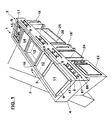
- FIG. 1 is a perspective view Kitchen equipment 1 regarded as particularly preferred illustrated, which is designed for wall mounting, wherein a mounting wall 2 has only been shown schematically. Such a wall 2 can also be seen in FIG. 2.
- the kitchen device 1 consists of an upper part 3, which is through a compact, tight, fully welded Frame 4 made of generally C-shaped CrNi sheet metal parts exists, cf. except Fig.1 also Fig.2, where the cross section of the Frame 4 and its central upper opening 5 can be seen are.
- the frame 4 has a body 6 of four mitred, tightly welded together Profiles 7 on, in particular two over the entire Length of the kitchen device 1 extending longitudinal profiles 7 (a front and a rear) and two over the Depth of the kitchen device 1 extending transverse profiles 7.
- the profiles 7 have a channel-shaped top Well 9 shaped so that one is around the Opening 5 extending gutter is formed, as out of Fig.2 in particular also emerges from Fig.1.
- This gutter-shaped Recess 9 closes on the inside as a boundary of the middle Opening 5 of the upper part 3 to a flange-like support strip 10 (see Fig. 2), which may be angled down at the inner edge and can be used to support an attached Work unit inserted into the opening 5 of the frame 3 serves.
- Such work units are, for example 1 a large cooktop 11, a grill plate 12, a Pan 13, a work surface 14 and a deep fryer 15 illustrated.
- thermal or non-thermal - components or general Work units such as warming surfaces, induction cooking surfaces etc.; ceramic hobs in particular can be used as hobs Find use, with highly polished surfaces can be provided to prevent food residues from accumulating, Counteract grease or general dirt.
- transverse gutter parts 16 may be used, the open into the circumferential drainage channel 9 at the front and rear.
- the gutter 9 drains 17 which, like is also indicated schematically in FIG. 2, simply from drain pipes can exist, which open out at the bottom but preferably with a shut-off device, not shown can be provided.
- a movable, cart-like collecting container module 18 is inserted, s. in addition to Fig. 1 also Fig. 8.
- This collection container module consists for example - according to Figure 8 - with a car Wheels or rollers 19 on which several, e.g. three, storage tanks 20, 21, 22 for the separate collection and disposal of solid kitchen waste; Meat residues; as well as fats or water (Rinse water) or overflowing food - preferably removable - are provided.
- This collecting container module 18 represents one of several possible substructure modules for kitchen equipment 1, in Figure 1 a further movable collecting container module 18 'is shown inserted in an inoperative position.
- substructure modules with suspension on Upper part 3, for example an oven module 23, an open one Cabinet element module 24 and an open cabinet element module 25 illustrated with intermediate board 26.
- oven module 23 could also be a movable module with Wheels or rollers, similar to the collection container modules 18, 18 ', his.
- substructure modules that can be suspended or attached are preferred, this releasable hanging attachment below is to be explained in particular with reference to FIG.
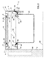
- Fig.2 is an example of the open at the front Cabinet element 24 as a substructure module illustrates which the underside of the upper part 3, i.e. of the frame 4, hung is a solution in a simple manner, without the aid of special tools, is possible; in this way the Order of substructure modules, e.g. 23, 24, 25 according to Fig.1, at the kitchen equipment 1 can be designed individually. Furthermore, by unhooking and taking away these base modules also conveniently created access to the underside of the upper part 3 be, accordingly the attachment of the work units 11 to 15 in the frame 4 of the upper part 3 from the bottom forth and can be made. In particular, how is shown, for example, in FIG.
- the substructure modules e.g. a cabinet module 24 as shown in FIG. 2, being carried by the flanges 30, 31 of the frame profiles 7 become.
- these flanges 30, 31 are angled Welded rails 32, 33, on which also on the top a cover 34 can be attached and screwed tight can, as illustrated at 35.
- a (Teflon) seal 28 may be interposed.
- the rails 32, 33 define lower contact surfaces 36 for flange-like suspension projections 37, 37 'on the upper longitudinal edges of the substructure module 24, see. except Fig.2 in particular Figure 3. It can be seen from Figure 3 that the cabinet module 24th apart from the front formed by an angle bar Suspension projection 37, on the front 38 as well as on the Top 39 is open.
- substructure module 24 with its suspension projections 37, 37 ' rest on the bearing surfaces 36 and thereby on adjacent bends of rails 32, 33 abut substructure module 24 can, however, be inclined slightly for hanging or unhooking and in the manner of "threading” or “threading” through the Opening between the facing edges of the flanges 30, 31 are passed.
- This tilting or sloping of the substructure module 24 is through an oblique transition 41 front rail 32 relieved; this sloping transition 41 in The front suspension projection 37 leads in the form of an inclined ramp of the substructure module 24 when pulling the same, whereby it a tipping and lifting of the front comes; Because of this Move forward (to the right in Fig.
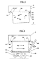
- FIG 24 A position of the substructure module is shown schematically in FIG 24, in which the front hook-in projection 37 the oblique Transition 41 is led upwards, so that for hanging of the module 24 in the lower opening of the frame 4 the rear Suspension projection 37 'past the rear flange 31 can be, as illustrated by arrow 42.
- the front of the base module was as described 24 moved slightly forward, see p. Arrow 44, the front suspension projection 37 at the transition 41 obliquely to the front was led above.
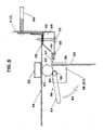
- the carriage 40 47 upstanding edges at the two ends of its support surface 54, 55, so as to attach or detach the base module 24 when tilting forward or backward against slipping to secure. Laterally, the bearing surface 47 is free, so that with one and the same car 40 base modules with the most varied Widths (see for example the modules 24, 25 in Fig. 1) can be attached or detached.
- the bearing surface 47 and the edges 54, 55 are not homogeneous, must be plate-shaped parts, but also by lattice-like or rust-like structures can be formed. In particular, the edges 54, 55 can also be bow-shaped bent rods have been preserved. It is only essential that the Rocker arm 49 (handlebar) firmly connected to the support surface 47 is, the stability must be sufficient to the largest, i.e. most difficult to be able to mount and unmount sub-modules.
- Substructure modules e.g. 24, not only in the longitudinal direction of the Rails 32, 33, but above all also transversely thereto, that is in particular according to the representation in Fig. 2 to the right (to the front), to prevent is in the front upper area of each Substructure module, e.g. 24, adjacent to the suspension projection 37, a locking part 56 in the form of a locking lever attached, the in one of the suspension projection 37 with its upper, horizontal flange defining angle profile strip inside welded-on tabs 57, 58 (see also, in particular, except for FIG. 6) Fig.7), namely in the upward open, otherwise circular arc Bearing recesses 59, pivotable with a rod part 60 is stored.
- the rod part 60 is a handle 61 completed, which forms the one lever arm of the locking lever 56.
- the other lever arm 62 is against the cover by one 34 of the upper part 3 expandable tubular body 63 is formed.
- This Tubular body 63 lies in the locking position shown in FIG or blocking position on the one hand on the upper edge of the body of the Sub-module 24 and on the other hand on the underside of the cover 34, in an "over-dead-center position" from which he by pivoting the handle 61 firmly connected to it in the direction of arrow 64 (see Fig. 6) - with a slight elasticity Deflection of the cover 34 upwards - in a release position can be moved.
- stiffening in this spreading of the Locking lever 56 against the cover 34 is on this one in Cross-section of rectangular stiffening molded pipe 65 welded on.
- FIG. 6 it is a suspension part provided angled rail 32 to the front pulled up to reinforce when screwing on a To serve limiting or protective bracket 66, the - s. also Fig. 1 - for limiting and as a ram protection of a control panel with Operating handles or the like. Controls 67 is used.
- Operating handles also e.g. Touch or sensor fields as control elements be provided for the work units 11 to 15.
- the kitchen device 1 thus described a homogeneous, compact, seamless top 3, the is easy to clean, and it is not possible from the outset offers for the preparation of leftovers and the like that a high level of hygiene is guaranteed. Furthermore is through the described modular system regarding work units as well as substructures a high degree of flexibility for given individual designs.
- a support 69 of which horizontal rails 70 for the attachment (and adjustment) of the Protruding top 3 of the kitchen device 1 to the outside, and preferably at the outer edges of the kitchen device 1. Accordingly, the entire kitchen device 1 is to be attached to the wall, where below the suspended base modules, e.g. 24, ground clearance is given. If necessary, however also, should this be desired, on the outer edges or Broad sides of the kitchen device 1 in itself conventional Way uprights are attached to the kitchen equipment 1 on the Supporting the floor should not be possible to fix it to the wall his.
- the profiles 7 for the frame 4 of the upper part 3 exist preferably from a 3 mm CrNi sheet, whereas the substructure modules, e.g. 24, 25, can consist of a 2 mm CrNi sheet.
- the kitchen device 1 described is particularly suitable for so-called "professional" kitchens or commercial kitchens, for example for Hospitals or restaurants where strict hygiene regulations apply and wherever there is a high degree of mobility or Variability of the individual substructures as well as work units is desired. From the above explanations, that the substructure modules in particular are simply attached, along the rails 32, 33 over the entire length of the Kitchen equipment 1 moved and with the help of the locking lever 56 can be fixed, and that the work units 11th up to 15 simply loosened from the bottom, removed, on can be used elsewhere and fixed again.
Landscapes
- Combinations Of Kitchen Furniture (AREA)
- Frying-Pans Or Fryers (AREA)
Description
Claims (14)
- Kücheneinrichtung mit einem rechteckförmigen Oberteil (3) mit einer Öffnung (5), in welche wenigstens eine Arbeitseinheit (11 bis 15) lösbar eingesetzt ist, und mit wenigstens einem hängend befestigten Unterbau (z.B. 24), dadurch gekennzeichnet, daß der Oberteil (3) ein Rahmen-Korpus (6) aus allgemein C-förmigen, an den Rahmenecken (8) miteinander dicht verschweißten Metallprofilen (7) ist, der einen nach außen fugenlosen Rahmen (4) bildet, der eine mittige Öffnung (5) zum Einsetzen der Arbeitseinheit(en) (11 bis 15) aufweist, wobei an der Unterseite des Rahmens (4) benachbart der Öffnung (5) Aufhängeteile zum lösbaren Aufhängen des modulartigen Unterbaus (z.B. 24) vorgesehen sind.
- Kücheneinrichtung nach Anspruch 1, dadurch gekennzeichnet, daß der Rahmen (4) an seiner Oberseite, um die mittige Öffnung (5) herum verlaufend, eine rinnenförmige Vertiefung (9) aufweist.
- Kücheneinrichtung nach Anspruch 2, dadurch gekennzeichnet, daß an die rinnenförmige Vertiefung (9) wenigstens ein nach unten führender Ablauf (17) angeschlossen ist.
- Kücheneinrichtung nach Anspruch 3, dadurch gekennzeichnet, daß unterhalb des Ablaufs (17) als Unterbau ein vorzugsweise verfahrbares Sammelbehälter-Modul (18; 18') vorgesehen ist.
- Kücheneinrichtung nach einem der Ansprüche 1 bis 4, dadurch gekennzeichnet, daß die jeweilige Arbeitseinheit (11 bis 15) mit, gegebenenfalls umgebogenen, flanschartigen Rändern (27) auf die mittige Öffnung (5) begrenzenden Tragleisten (10) aufgesetzt und unter Zwischenlage von Dichtungen (28) mit diesen Tragleisten (10) verschraubt ist.
- Kücheneinrichtung nach einem der Ansprüche 1 bis 5, dadurch gekennzeichnet, daß die Aufhängeteile durch abgewinkelte Schienen (32, 33) gebildet sind, und das Unterbau-Modul (24) flanschartige Aufhäng-Vorsprünge (37) besitzt.
- Kücheneinrichtung nach Anspruch 6, dadurch gekennzeichnet, daß die eine Schiene (32) einen von einer Auflagefläche (36) schräg hochführenden Übergang (41) aufweist.
- Kücheneinrichtung nach Anspruch 6 oder 7, dadurch gekennzeichnet, daß der Abstand zwischen den einander zugewandten Rändern der Schienen (32, 33) kleiner ist als die Tiefe des Unterbau-Moduls (24), gemessen zwischen den voneinander abgewandten Rändern der Aufhäng-Vorsprünge (27), jedoch größer ist als die Tiefe des Korpus des Unterbau-Moduls (24), wobei das jeweilige Unterbau-Modul (24) im aufgehängten Zustand mit seinen Aufhäng-Vorsprüngen (37) an Abwinkelungen (z.B. 41) anstößt, die Auflageflächen (36) der Schienen (32, 33) begrenzen, auf denen die Aufhäng-Vorsprünge (37) aufliegen.
- Kücheneinrichtung nach einem der Ansprüche 1 bis 8, dadurch gekennzeichnet, daß das Unterbau-Modul (24) an seinen oberen, vorderen Randbereich einen mit dem Oberteil (3) zusammenarbeitenden Arretierteil (56) zur Arretierung des Unterbau-Moduls (24) am Oberteil (3) im aufgehängten Zustand aufweist.
- Kücheneinrichtung nach den Ansprüchen 8 und 9, dadurch gekennzeichnet, daß der Arretierteil durch einen Arretierhebel (56) mit einem gegen den Oberteil (3) verspreizbaren Hebelarm (62) gebildet ist.
- Kücheneinrichtung nach einem der Ansprüche 1 bis 10, dadurch gekennzeichnet, daß das Unterbau-Modul (24) oben offen ausgebildet ist.
- Kücheneinrichtung nach einem der Ansprüche 1 bis 11, dadurch gekennzeichnet, daß der Oberteil-Rahmen (4) für eine bloße Wandbefestigung ausgebildet ist.
- Kücheneinrichtung nach einem der Ansprüche 1 bis 12, dadurch gekennzeichnet, daß der Oberteil-Rahmen (4) aus einem CrNi-Blech, z.B. mit einer Stärke von ca. 3 mm, besteht.
- Kücheneinrichtung nach einem der Ansprüche 1 bis 13, dadurch gekennzeichnet, daß der Korpus des Unterbau-Moduls (24) aus einem CrNi-Blech, z.B. mit einer Stärke von ca. 2 mm, besteht.
Priority Applications (1)
| Application Number | Priority Date | Filing Date | Title |
|---|---|---|---|
| AT97942700T ATE237975T1 (de) | 1996-11-08 | 1997-10-13 | Kücheneinrichtung mit oberteil und mit wenigstens einem unterbau, und wagen zum ein- und aushängen eines unterbau-moduls an einem oberteil |
Applications Claiming Priority (4)
| Application Number | Priority Date | Filing Date | Title |
|---|---|---|---|
| AT65696U AT1702U1 (de) | 1996-11-08 | 1996-11-08 | Kücheneinrichtung |
| AT65696 | 1996-11-08 | ||
| AT65696U | 1996-11-08 | ||
| PCT/AT1997/000217 WO1998020776A1 (de) | 1996-11-08 | 1997-10-13 | Kücheneinrichtung mit oberteil und mit wenigstens einem unterbau, und wagen zum ein- und aushängen eines unterbau-moduls an einem oberteil |
Publications (2)
| Publication Number | Publication Date |
|---|---|
| EP1011380A1 EP1011380A1 (de) | 2000-06-28 |
| EP1011380B1 true EP1011380B1 (de) | 2003-04-23 |
Family
ID=3496367
Family Applications (1)
| Application Number | Title | Priority Date | Filing Date |
|---|---|---|---|
| EP97942700A Expired - Lifetime EP1011380B1 (de) | 1996-11-08 | 1997-10-13 | Kücheneinrichtung mit oberteil und mit wenigstens einem unterbau, und wagen zum ein- und aushängen eines unterbau-moduls an einem oberteil |
Country Status (7)
| Country | Link |
|---|---|
| EP (1) | EP1011380B1 (de) |
| AT (1) | AT1702U1 (de) |
| AU (1) | AU4444697A (de) |
| DE (2) | DE59709934D1 (de) |
| PL (1) | PL334874A1 (de) |
| WO (1) | WO1998020776A1 (de) |
| YU (1) | YU21699A (de) |
Cited By (1)
| Publication number | Priority date | Publication date | Assignee | Title |
|---|---|---|---|---|
| US20240306812A1 (en) * | 2021-02-15 | 2024-09-19 | Efendi Proje Mimarlik Muhendislik Sanayi Ve Ticaret Limited Sirketi | Modular workstation |
Families Citing this family (5)
| Publication number | Priority date | Publication date | Assignee | Title |
|---|---|---|---|---|
| NL1012371C2 (nl) * | 1999-06-16 | 2000-12-19 | Holec Holland Nv | Spoelbakkeukenkast met subverdeelinrichting. |
| WO2009050091A2 (de) * | 2007-10-12 | 2009-04-23 | BSH Bosch und Siemens Hausgeräte GmbH | Kochfeld, insbesondere gaskochfeld |
| SE535103C2 (sv) * | 2009-11-13 | 2012-04-17 | Elektrotermo Ab | Bänkanordning för skåp |
| DE102011115109B4 (de) * | 2011-10-07 | 2016-09-01 | Claudia Musch | Mobile Küchenvorrichtung |
| WO2017025919A2 (en) | 2015-08-10 | 2017-02-16 | Duke Manufacturing Co. | Food serving station and associated appliances and methods |
Family Cites Families (11)
| Publication number | Priority date | Publication date | Assignee | Title |
|---|---|---|---|---|
| SE194849C1 (de) * | ||||
| US3746416A (en) * | 1971-07-01 | 1973-07-17 | Gen Electric | Modular furniture system and means for manipulating and connecting components thereof |
| DE2407582C3 (de) * | 1974-02-16 | 1981-02-26 | Licentia Patent-Verwaltungs-Gmbh, 6000 Frankfurt | Einbaukochfläche aus Glas o.dgl. mit mehreren Einzelkochstellen für Einbauküchenmöbel |
| DE2917144A1 (de) * | 1979-04-27 | 1980-11-06 | Schwarzwaelder Kuechenmoebelwe | Arbeitsplatte fuer einbaukuechen mit einem eingelassenen einbauteil und verfahren zum herstellen einer solchen arbeitsplatte |
| US4562827A (en) * | 1984-11-21 | 1986-01-07 | Roper Corporation | Downdraft countertop cooking range |
| DE3730901A1 (de) * | 1987-09-15 | 1989-03-23 | Schock & Co Gmbh | Tischplatte mit eingesetztem formteil |
| FR2644047B1 (fr) * | 1989-03-10 | 1992-05-15 | Barthelemy Auffray | Meuble de cuisine |
| NL9002266A (nl) * | 1990-10-18 | 1992-05-18 | Ahrend Groep Nv | Van wielen of rollen voorziene bergkast. |
| DE4034250A1 (de) * | 1990-10-27 | 1992-04-30 | Juno Grosskuechen | Verbindungsvorrichtung fuer nebeneinander stehende grosskuechengeraete |
| DE4306545C1 (de) * | 1993-03-03 | 1994-04-21 | Neubauer Kurt Maschf | Küche mit benachbarten Funktionseinheiten |
| ES2078160B1 (es) * | 1993-11-08 | 1998-06-16 | Fagor S Coop | Disposicion de modulos de cocinado comerciales. |
-
1996
- 1996-11-08 AT AT65696U patent/AT1702U1/de not_active IP Right Cessation
-
1997
- 1997-10-13 YU YU21699A patent/YU21699A/sh unknown
- 1997-10-13 PL PL97334874A patent/PL334874A1/xx unknown
- 1997-10-13 EP EP97942700A patent/EP1011380B1/de not_active Expired - Lifetime
- 1997-10-13 DE DE59709934T patent/DE59709934D1/de not_active Expired - Fee Related
- 1997-10-13 WO PCT/AT1997/000217 patent/WO1998020776A1/de not_active Ceased
- 1997-10-13 DE DE19781256T patent/DE19781256D2/de not_active Ceased
- 1997-10-13 AU AU44446/97A patent/AU4444697A/en not_active Abandoned
Cited By (1)
| Publication number | Priority date | Publication date | Assignee | Title |
|---|---|---|---|---|
| US20240306812A1 (en) * | 2021-02-15 | 2024-09-19 | Efendi Proje Mimarlik Muhendislik Sanayi Ve Ticaret Limited Sirketi | Modular workstation |
Also Published As
| Publication number | Publication date |
|---|---|
| YU21699A (sh) | 2000-03-21 |
| EP1011380A1 (de) | 2000-06-28 |
| DE19781256D2 (de) | 2000-08-03 |
| AU4444697A (en) | 1998-06-03 |
| WO1998020776A1 (de) | 1998-05-22 |
| PL334874A1 (en) | 2000-03-27 |
| AT1702U1 (de) | 1997-10-27 |
| DE59709934D1 (de) | 2003-05-28 |
Similar Documents
| Publication | Publication Date | Title |
|---|---|---|
| EP1306622B1 (de) | Schienensystem für Gargutträger in einem Backofen | |
| DE19515080C2 (de) | Grillgerät insbesondere mit Holzkohlefeuerung | |
| EP1011380B1 (de) | Kücheneinrichtung mit oberteil und mit wenigstens einem unterbau, und wagen zum ein- und aushängen eines unterbau-moduls an einem oberteil | |
| DE10241486B4 (de) | Garofenmuffel mit einem über dem Muffelboden angeordneten Unterhitzeheizkörper | |
| DE10116098A1 (de) | Küchensystem | |
| DE102020206185B4 (de) | Beistellwagen sowie Küchensystem mit einem Beistellwagen | |
| DE4446757C3 (de) | Back- und Bratofen mit einem Teleskopwagen | |
| DE3128944C2 (de) | Auflagerost für einen Herd mit Back- und Bratraum | |
| DE102011115109B4 (de) | Mobile Küchenvorrichtung | |
| EP4374746A1 (de) | Küchengerät | |
| EP2284447B1 (de) | Garofenmuffel | |
| DE69815896T2 (de) | Tablett zum tragen von gegenständen, insbesondere für kühlschränke | |
| EP1376019A1 (de) | Garofenmuffel | |
| DE10241489A1 (de) | Teleskopartiges System und Auszug für einen Gargutträger | |
| DE8020612U1 (de) | Kuchenform | |
| DE20216417U1 (de) | Spritzschutz | |
| DE3602454C2 (de) | ||
| EP1376017A1 (de) | Teleskopartiges System und Auszug für einen Gargutträger | |
| DE202007009433U1 (de) | Mobile Küche | |
| DE10062116C2 (de) | Backofen | |
| EP4374747A1 (de) | Küchengerät | |
| DE102023130756A1 (de) | Küchengerät | |
| DE202023105906U1 (de) | Mobile Küche, Austauscharbeitsfläche und Küchengestell | |
| EP4374745A1 (de) | Küchengerät | |
| DE202013003343U1 (de) | Raclette-Gerät |
Legal Events
| Date | Code | Title | Description |
|---|---|---|---|
| PUAI | Public reference made under article 153(3) epc to a published international application that has entered the european phase |
Free format text: ORIGINAL CODE: 0009012 |
|
| 17P | Request for examination filed |
Effective date: 19990504 |
|
| AK | Designated contracting states |
Kind code of ref document: A1 Designated state(s): AT BE CH DE DK FI FR GR IT LI NL SE |
|
| AX | Request for extension of the european patent |
Free format text: SI PAYMENT 19990505 |
|
| 17Q | First examination report despatched |
Effective date: 20010710 |
|
| RAP1 | Party data changed (applicant data changed or rights of an application transferred) |
Owner name: LOHBERGER, HEIZ + KOCHGERAETE-TECHNOLOGIE GMBH |
|
| GRAH | Despatch of communication of intention to grant a patent |
Free format text: ORIGINAL CODE: EPIDOS IGRA |
|
| GRAH | Despatch of communication of intention to grant a patent |
Free format text: ORIGINAL CODE: EPIDOS IGRA |
|
| GRAA | (expected) grant |
Free format text: ORIGINAL CODE: 0009210 |
|
| AK | Designated contracting states |
Designated state(s): AT BE CH DE DK FI FR GR IT LI NL SE |
|
| AX | Request for extension of the european patent |
Extension state: SI |
|
| PG25 | Lapsed in a contracting state [announced via postgrant information from national office to epo] |
Ref country code: FR Free format text: LAPSE BECAUSE OF FAILURE TO SUBMIT A TRANSLATION OF THE DESCRIPTION OR TO PAY THE FEE WITHIN THE PRESCRIBED TIME-LIMIT Effective date: 20030423 Ref country code: FI Free format text: LAPSE BECAUSE OF FAILURE TO SUBMIT A TRANSLATION OF THE DESCRIPTION OR TO PAY THE FEE WITHIN THE PRESCRIBED TIME-LIMIT Effective date: 20030423 |
|
| RAX | Requested extension states of the european patent have changed |
Extension state: SI Payment date: 19990504 |
|
| RIN1 | Information on inventor provided before grant (corrected) |
Inventor name: MARCHHART, WOLFGANG |
|
| REG | Reference to a national code |
Ref country code: CH Ref legal event code: EP |
|
| REF | Corresponds to: |
Ref document number: 59709934 Country of ref document: DE Date of ref document: 20030528 Kind code of ref document: P |
|
| REG | Reference to a national code |
Ref country code: CH Ref legal event code: NV Representative=s name: SPIERENBURG & PARTNER AG, PATENT- UND MARKENANWAEL |
|
| PG25 | Lapsed in a contracting state [announced via postgrant information from national office to epo] |
Ref country code: SE Free format text: LAPSE BECAUSE OF FAILURE TO SUBMIT A TRANSLATION OF THE DESCRIPTION OR TO PAY THE FEE WITHIN THE PRESCRIBED TIME-LIMIT Effective date: 20030723 Ref country code: GR Free format text: LAPSE BECAUSE OF FAILURE TO SUBMIT A TRANSLATION OF THE DESCRIPTION OR TO PAY THE FEE WITHIN THE PRESCRIBED TIME-LIMIT Effective date: 20030723 Ref country code: DK Free format text: LAPSE BECAUSE OF FAILURE TO SUBMIT A TRANSLATION OF THE DESCRIPTION OR TO PAY THE FEE WITHIN THE PRESCRIBED TIME-LIMIT Effective date: 20030723 |
|
| PG25 | Lapsed in a contracting state [announced via postgrant information from national office to epo] |
Ref country code: LI Free format text: LAPSE BECAUSE OF NON-PAYMENT OF DUE FEES Effective date: 20031031 Ref country code: CH Free format text: LAPSE BECAUSE OF NON-PAYMENT OF DUE FEES Effective date: 20031031 Ref country code: BE Free format text: LAPSE BECAUSE OF NON-PAYMENT OF DUE FEES Effective date: 20031031 |
|
| PLBE | No opposition filed within time limit |
Free format text: ORIGINAL CODE: 0009261 |
|
| STAA | Information on the status of an ep patent application or granted ep patent |
Free format text: STATUS: NO OPPOSITION FILED WITHIN TIME LIMIT |
|
| 26N | No opposition filed |
Effective date: 20040126 |
|
| EN | Fr: translation not filed | ||
| BERE | Be: lapsed |
Owner name: *LOHBERGER HEIZ + KOCHGERATE-TECHNOLOGIE G.M.B.H. Effective date: 20031031 |
|
| PG25 | Lapsed in a contracting state [announced via postgrant information from national office to epo] |
Ref country code: NL Free format text: LAPSE BECAUSE OF NON-PAYMENT OF DUE FEES Effective date: 20040501 |
|
| REG | Reference to a national code |
Ref country code: CH Ref legal event code: PL |
|
| NLV4 | Nl: lapsed or anulled due to non-payment of the annual fee |
Effective date: 20040501 |
|
| PGFP | Annual fee paid to national office [announced via postgrant information from national office to epo] |
Ref country code: AT Payment date: 20041021 Year of fee payment: 8 |
|
| PGFP | Annual fee paid to national office [announced via postgrant information from national office to epo] |
Ref country code: DE Payment date: 20041029 Year of fee payment: 8 |
|
| PG25 | Lapsed in a contracting state [announced via postgrant information from national office to epo] |
Ref country code: IT Free format text: LAPSE BECAUSE OF NON-PAYMENT OF DUE FEES Effective date: 20051013 Ref country code: AT Free format text: LAPSE BECAUSE OF NON-PAYMENT OF DUE FEES Effective date: 20051013 |
|
| PG25 | Lapsed in a contracting state [announced via postgrant information from national office to epo] |
Ref country code: DE Free format text: LAPSE BECAUSE OF NON-PAYMENT OF DUE FEES Effective date: 20060503 |