EP1011589B1 - Humidificateur pour appareil d'assistance thermique - Google Patents
Humidificateur pour appareil d'assistance thermique Download PDFInfo
- Publication number
- EP1011589B1 EP1011589B1 EP98944806A EP98944806A EP1011589B1 EP 1011589 B1 EP1011589 B1 EP 1011589B1 EP 98944806 A EP98944806 A EP 98944806A EP 98944806 A EP98944806 A EP 98944806A EP 1011589 B1 EP1011589 B1 EP 1011589B1
- Authority
- EP
- European Patent Office
- Prior art keywords
- patient support
- support apparatus
- humidifier module
- door
- opening
- Prior art date
- Legal status (The legal status is an assumption and is not a legal conclusion. Google has not performed a legal analysis and makes no representation as to the accuracy of the status listed.)
- Expired - Lifetime
Links
- XLYOFNOQVPJJNP-UHFFFAOYSA-N water Substances O XLYOFNOQVPJJNP-UHFFFAOYSA-N 0.000 claims description 94
- 239000012530 fluid Substances 0.000 claims description 28
- 238000003780 insertion Methods 0.000 claims description 9
- 230000037431 insertion Effects 0.000 claims description 9
- 238000010438 heat treatment Methods 0.000 claims description 4
- 230000013011 mating Effects 0.000 claims description 4
- 230000000903 blocking effect Effects 0.000 claims description 3
- 230000001419 dependent effect Effects 0.000 claims 2
- 230000005484 gravity Effects 0.000 claims 1
- 238000002955 isolation Methods 0.000 description 12
- 238000005192 partition Methods 0.000 description 6
- 230000001276 controlling effect Effects 0.000 description 3
- 238000012544 monitoring process Methods 0.000 description 3
- NJPPVKZQTLUDBO-UHFFFAOYSA-N novaluron Chemical compound C1=C(Cl)C(OC(F)(F)C(OC(F)(F)F)F)=CC=C1NC(=O)NC(=O)C1=C(F)C=CC=C1F NJPPVKZQTLUDBO-UHFFFAOYSA-N 0.000 description 3
- 230000000712 assembly Effects 0.000 description 2
- 238000000429 assembly Methods 0.000 description 2
- 230000000994 depressogenic effect Effects 0.000 description 2
- 239000000203 mixture Substances 0.000 description 2
- 230000007704 transition Effects 0.000 description 2
- 235000004443 Ricinus communis Nutrition 0.000 description 1
- 240000000528 Ricinus communis Species 0.000 description 1
- 238000006243 chemical reaction Methods 0.000 description 1
- 230000003750 conditioning effect Effects 0.000 description 1
- 230000002596 correlated effect Effects 0.000 description 1
- 230000007423 decrease Effects 0.000 description 1
- 230000007613 environmental effect Effects 0.000 description 1
- 238000001704 evaporation Methods 0.000 description 1
- 230000008020 evaporation Effects 0.000 description 1
- 239000007788 liquid Substances 0.000 description 1
- 230000003287 optical effect Effects 0.000 description 1
- 230000003134 recirculating effect Effects 0.000 description 1
- 239000007787 solid Substances 0.000 description 1
- 238000010792 warming Methods 0.000 description 1
Images




Classifications
-
- F—MECHANICAL ENGINEERING; LIGHTING; HEATING; WEAPONS; BLASTING
- F24—HEATING; RANGES; VENTILATING
- F24F—AIR-CONDITIONING; AIR-HUMIDIFICATION; VENTILATION; USE OF AIR CURRENTS FOR SCREENING
- F24F9/00—Use of air currents for screening, e.g. air curtains
-
- A—HUMAN NECESSITIES
- A61—MEDICAL OR VETERINARY SCIENCE; HYGIENE
- A61G—TRANSPORT, PERSONAL CONVEYANCES, OR ACCOMMODATION SPECIALLY ADAPTED FOR PATIENTS OR DISABLED PERSONS; OPERATING TABLES OR CHAIRS; CHAIRS FOR DENTISTRY; FUNERAL DEVICES
- A61G11/00—Baby-incubators; Couveuses
-
- A—HUMAN NECESSITIES
- A61—MEDICAL OR VETERINARY SCIENCE; HYGIENE
- A61M—DEVICES FOR INTRODUCING MEDIA INTO, OR ONTO, THE BODY; DEVICES FOR TRANSDUCING BODY MEDIA OR FOR TAKING MEDIA FROM THE BODY; DEVICES FOR PRODUCING OR ENDING SLEEP OR STUPOR
- A61M16/00—Devices for influencing the respiratory system of patients by gas treatment, e.g. ventilators; Tracheal tubes
- A61M16/021—Devices for influencing the respiratory system of patients by gas treatment, e.g. ventilators; Tracheal tubes operated by electrical means
- A61M16/022—Control means therefor
- A61M16/024—Control means therefor including calculation means, e.g. using a processor
-
- A—HUMAN NECESSITIES
- A61—MEDICAL OR VETERINARY SCIENCE; HYGIENE
- A61M—DEVICES FOR INTRODUCING MEDIA INTO, OR ONTO, THE BODY; DEVICES FOR TRANSDUCING BODY MEDIA OR FOR TAKING MEDIA FROM THE BODY; DEVICES FOR PRODUCING OR ENDING SLEEP OR STUPOR
- A61M16/00—Devices for influencing the respiratory system of patients by gas treatment, e.g. ventilators; Tracheal tubes
- A61M16/10—Preparation of respiratory gases or vapours
- A61M16/1075—Preparation of respiratory gases or vapours by influencing the temperature
- A61M16/109—Preparation of respiratory gases or vapours by influencing the temperature the humidifying liquid or the beneficial agent
-
- A—HUMAN NECESSITIES
- A61—MEDICAL OR VETERINARY SCIENCE; HYGIENE
- A61M—DEVICES FOR INTRODUCING MEDIA INTO, OR ONTO, THE BODY; DEVICES FOR TRANSDUCING BODY MEDIA OR FOR TAKING MEDIA FROM THE BODY; DEVICES FOR PRODUCING OR ENDING SLEEP OR STUPOR
- A61M16/00—Devices for influencing the respiratory system of patients by gas treatment, e.g. ventilators; Tracheal tubes
- A61M16/10—Preparation of respiratory gases or vapours
- A61M16/14—Preparation of respiratory gases or vapours by mixing different fluids, one of them being in a liquid phase
- A61M16/16—Devices to humidify the respiration air
-
- G—PHYSICS
- G05—CONTROLLING; REGULATING
- G05D—SYSTEMS FOR CONTROLLING OR REGULATING NON-ELECTRIC VARIABLES
- G05D23/00—Control of temperature
- G05D23/19—Control of temperature characterised by the use of electric means
- G05D23/1917—Control of temperature characterised by the use of electric means using digital means
-
- A—HUMAN NECESSITIES
- A61—MEDICAL OR VETERINARY SCIENCE; HYGIENE
- A61F—FILTERS IMPLANTABLE INTO BLOOD VESSELS; PROSTHESES; DEVICES PROVIDING PATENCY TO, OR PREVENTING COLLAPSING OF, TUBULAR STRUCTURES OF THE BODY, e.g. STENTS; ORTHOPAEDIC, NURSING OR CONTRACEPTIVE DEVICES; FOMENTATION; TREATMENT OR PROTECTION OF EYES OR EARS; BANDAGES, DRESSINGS OR ABSORBENT PADS; FIRST-AID KITS
- A61F7/00—Heating or cooling appliances for medical or therapeutic treatment of the human body
- A61F2007/0059—Heating or cooling appliances for medical or therapeutic treatment of the human body with an open fluid circuit
- A61F2007/006—Heating or cooling appliances for medical or therapeutic treatment of the human body with an open fluid circuit of gas
-
- A—HUMAN NECESSITIES
- A61—MEDICAL OR VETERINARY SCIENCE; HYGIENE
- A61F—FILTERS IMPLANTABLE INTO BLOOD VESSELS; PROSTHESES; DEVICES PROVIDING PATENCY TO, OR PREVENTING COLLAPSING OF, TUBULAR STRUCTURES OF THE BODY, e.g. STENTS; ORTHOPAEDIC, NURSING OR CONTRACEPTIVE DEVICES; FOMENTATION; TREATMENT OR PROTECTION OF EYES OR EARS; BANDAGES, DRESSINGS OR ABSORBENT PADS; FIRST-AID KITS
- A61F7/00—Heating or cooling appliances for medical or therapeutic treatment of the human body
- A61F2007/0088—Radiating heat
-
- A—HUMAN NECESSITIES
- A61—MEDICAL OR VETERINARY SCIENCE; HYGIENE
- A61G—TRANSPORT, PERSONAL CONVEYANCES, OR ACCOMMODATION SPECIALLY ADAPTED FOR PATIENTS OR DISABLED PERSONS; OPERATING TABLES OR CHAIRS; CHAIRS FOR DENTISTRY; FUNERAL DEVICES
- A61G11/00—Baby-incubators; Couveuses
- A61G11/001—Baby-incubators; Couveuses with height-adjustable elements
- A61G11/002—Baby-incubators; Couveuses with height-adjustable elements height-adjustable patient support
-
- A—HUMAN NECESSITIES
- A61—MEDICAL OR VETERINARY SCIENCE; HYGIENE
- A61G—TRANSPORT, PERSONAL CONVEYANCES, OR ACCOMMODATION SPECIALLY ADAPTED FOR PATIENTS OR DISABLED PERSONS; OPERATING TABLES OR CHAIRS; CHAIRS FOR DENTISTRY; FUNERAL DEVICES
- A61G11/00—Baby-incubators; Couveuses
- A61G11/005—Baby-incubators; Couveuses with movable walls, e.g. for accessing the inside, removable walls
-
- A—HUMAN NECESSITIES
- A61—MEDICAL OR VETERINARY SCIENCE; HYGIENE
- A61G—TRANSPORT, PERSONAL CONVEYANCES, OR ACCOMMODATION SPECIALLY ADAPTED FOR PATIENTS OR DISABLED PERSONS; OPERATING TABLES OR CHAIRS; CHAIRS FOR DENTISTRY; FUNERAL DEVICES
- A61G11/00—Baby-incubators; Couveuses
- A61G11/009—Baby-incubators; Couveuses with hand insertion windows, e.g. in the walls
-
- A—HUMAN NECESSITIES
- A61—MEDICAL OR VETERINARY SCIENCE; HYGIENE
- A61G—TRANSPORT, PERSONAL CONVEYANCES, OR ACCOMMODATION SPECIALLY ADAPTED FOR PATIENTS OR DISABLED PERSONS; OPERATING TABLES OR CHAIRS; CHAIRS FOR DENTISTRY; FUNERAL DEVICES
- A61G2203/00—General characteristics of devices
- A61G2203/30—General characteristics of devices characterised by sensor means
- A61G2203/46—General characteristics of devices characterised by sensor means for temperature
-
- A—HUMAN NECESSITIES
- A61—MEDICAL OR VETERINARY SCIENCE; HYGIENE
- A61G—TRANSPORT, PERSONAL CONVEYANCES, OR ACCOMMODATION SPECIALLY ADAPTED FOR PATIENTS OR DISABLED PERSONS; OPERATING TABLES OR CHAIRS; CHAIRS FOR DENTISTRY; FUNERAL DEVICES
- A61G2203/00—General characteristics of devices
- A61G2203/70—General characteristics of devices with special adaptations, e.g. for safety or comfort
- A61G2203/72—General characteristics of devices with special adaptations, e.g. for safety or comfort for collision prevention
- A61G2203/723—Impact absorbing means, e.g. bumpers or airbags
-
- A—HUMAN NECESSITIES
- A61—MEDICAL OR VETERINARY SCIENCE; HYGIENE
- A61G—TRANSPORT, PERSONAL CONVEYANCES, OR ACCOMMODATION SPECIALLY ADAPTED FOR PATIENTS OR DISABLED PERSONS; OPERATING TABLES OR CHAIRS; CHAIRS FOR DENTISTRY; FUNERAL DEVICES
- A61G2210/00—Devices for specific treatment or diagnosis
- A61G2210/50—Devices for specific treatment or diagnosis for radiography
-
- A—HUMAN NECESSITIES
- A61—MEDICAL OR VETERINARY SCIENCE; HYGIENE
- A61G—TRANSPORT, PERSONAL CONVEYANCES, OR ACCOMMODATION SPECIALLY ADAPTED FOR PATIENTS OR DISABLED PERSONS; OPERATING TABLES OR CHAIRS; CHAIRS FOR DENTISTRY; FUNERAL DEVICES
- A61G7/00—Beds specially adapted for nursing; Devices for lifting patients or disabled persons
- A61G7/002—Beds specially adapted for nursing; Devices for lifting patients or disabled persons having adjustable mattress frame
- A61G7/012—Beds specially adapted for nursing; Devices for lifting patients or disabled persons having adjustable mattress frame raising or lowering of the whole mattress frame
-
- A—HUMAN NECESSITIES
- A61—MEDICAL OR VETERINARY SCIENCE; HYGIENE
- A61M—DEVICES FOR INTRODUCING MEDIA INTO, OR ONTO, THE BODY; DEVICES FOR TRANSDUCING BODY MEDIA OR FOR TAKING MEDIA FROM THE BODY; DEVICES FOR PRODUCING OR ENDING SLEEP OR STUPOR
- A61M16/00—Devices for influencing the respiratory system of patients by gas treatment, e.g. ventilators; Tracheal tubes
- A61M16/10—Preparation of respiratory gases or vapours
- A61M16/105—Filters
- A61M16/106—Filters in a path
- A61M16/107—Filters in a path in the inspiratory path
-
- A—HUMAN NECESSITIES
- A61—MEDICAL OR VETERINARY SCIENCE; HYGIENE
- A61M—DEVICES FOR INTRODUCING MEDIA INTO, OR ONTO, THE BODY; DEVICES FOR TRANSDUCING BODY MEDIA OR FOR TAKING MEDIA FROM THE BODY; DEVICES FOR PRODUCING OR ENDING SLEEP OR STUPOR
- A61M2205/00—General characteristics of the apparatus
- A61M2205/33—Controlling, regulating or measuring
- A61M2205/3379—Masses, volumes, levels of fluids in reservoirs, flow rates
- A61M2205/3389—Continuous level detection
-
- F—MECHANICAL ENGINEERING; LIGHTING; HEATING; WEAPONS; BLASTING
- F24—HEATING; RANGES; VENTILATING
- F24F—AIR-CONDITIONING; AIR-HUMIDIFICATION; VENTILATION; USE OF AIR CURRENTS FOR SCREENING
- F24F11/00—Control or safety arrangements
- F24F11/30—Control or safety arrangements for purposes related to the operation of the system, e.g. for safety or monitoring
-
- F—MECHANICAL ENGINEERING; LIGHTING; HEATING; WEAPONS; BLASTING
- F24—HEATING; RANGES; VENTILATING
- F24F—AIR-CONDITIONING; AIR-HUMIDIFICATION; VENTILATION; USE OF AIR CURRENTS FOR SCREENING
- F24F2110/00—Control inputs relating to air properties
- F24F2110/10—Temperature
Definitions
- the present invention relates to patient-support devices, and particularly, to infant thermal support devices of the type having a humidity controlled environment for a patient supported by the device. More particularly, the present invention relates to a self-contained humidifier module that is inserted into a patient-support apparatus.
- a humidifier module according to the preamble of claim 1 is known from WO-A-97/11664.
- the present invention is a humidifier module for a patient-support apparatus including an opening into which the module is inserted, an electrical service connector, an air inlet port, and an air outlet port.
- the humidifier module which is to be inserted into the patient-support apparatus, comprises a water reservoir for holding water, a heater for heating the water, an air chamber with an air inlet port and an air exhaust port for mating with the air inlet and outlet ports of the support apparatus, and an electrical connector for mating with the electrical service connector of the patient-support apparatus.
- the patient-support apparatus is provided with a humidified environment for the patient when the humidifier module is inserted into the opening of the patient-support apparatus.
- the patient-support apparatus may include one or more external doors that normally close the opening of the patient-support apparatus. The external doors are opened by the insertion of the humidifier module through the opening of the patient support apparatus.
- the patient-support apparatus may also include one or more internal doors that normally close the air inlet and outlet ports of the patient-support apparatus. The internal doors are opened by the insertion of the humidifier module through the opening and into the patient-support apparatus.
- the humidifier module may include one or more spill damper doors that close the air inlet port and air exhaust port of the humidifier module to prevent hot water heated by the heater from spilling out of the humidifier module when the humidifier module is removed from the patient-support apparatus.
- the patient-support apparatus may include door opener tabs that engage and open the spill damper doors when the humidifier module is inserted into the patient-support apparatus.
- the humidifier module includes a pair of door openers that are positioned beneath the respective air inlet and exhaust ports and each door opener is formed to include a recess that catches any water that inadvertently spills out of the humidifier module through the air inlet and exhaust ports.
- the humidifier module can include a refill door that is positioned to lie outside a compartment of the patient-support apparatus in which the humidifier module is received.
- the refill door can be opened so that water can be poured into the water reservoir without having to remove the humidifier module from the patient-support apparatus.
- the patient-support apparatus of the present invention comprises a compartment for accepting a removable self-contained humidifier module, an air inlet in fluid communication with the compartment, an air outlet in fluid communication with the compartment, and an electrical service connector positioned to lie in the compartment.
- the humidifier module includes a water heater chamber and cooperating inlets and outlets for connecting with the air inlets and outlets of the patient-support when the humidifier module is inserted into the compartment.
- the humidifier module further includes an electrical connector that couples to the electrical service connector of the patient-support apparatus and a heater coupled to the electrical connector.
- the electrical connector of the humidifier module aligns with and automatically connects to the electrical service connector of the patient-support apparatus when the humidifier module is inserted into the patient-support apparatus.
- a patient-support apparatus having a patient support and a fluid circulation system with a flow path that directs circulated fluid through the patient support to provide a thermally controlled environment for a patient.
- the patient support includes a compartment for accepting a removable self-contained humidifier module, an inlet port in fluid communication with the compartment and an outlet port in fluid communication with the compartment.
- the apparatus also includes a first door pivotably coupled to the patient support and normally closing the inlet port, a second door pivotably coupled to the patient support and normally closing the outlet port.
- the humidifier module includes a water container for containing water, an inlet port for connecting with the outlet port of the patient-support when the humidifier module is inserted into the compartment, an exhaust port for connecting with the inlet port of the patient-support when the humidifier module is inserted into the compartment, and first and second door openers arranged to engage and pivot the respective first and second doors to an open position to allow at least some to the fluid in the first path to be diverted through the humidifier module and over the water contained in the water container.
- the preferred humidifier module of the present invention comprises a container for holding water and an air chamber above the water.
- the container may have an air inlet port and an air exhaust port providing for air flow movement through the chamber.
- the humidifier module includes a heater for heating the water and a water reservoir for holding additional water.
- the humidifier further includes a control valve coupled to the water reservoir and coupled to the container.
- the control valve has a closed configuration blocking the flow of water from the water reservoir to the container and the control valve has an opened configuration allowing the flow of water from the water reservoir to the container.
- a level sensor senses the water level in the container and provides a signal to the control valve to move the control valve between the opened and closed configurations.
- the preferred humidifier module comprises a locking mechanism that locks the humidifier module to the patient support of the patient-support apparatus when a temperature sensor, which is coupled to the locking mechanism, senses a temperature that exceeds a predetermined temperature.
- the locking mechanism includes a locking post and a solenoid that extends the locking post to a locking position and that retracts the locking post to a releasing position depending upon the temperature sensed by the temperature sensor.
- the patient-support apparatus is formed to include an aperture that receives the locking post when the locking post extends to the locking position.
- the patient-support apparatus comprises a patient support having a first chamber, a second chamber and a fluid-flow orifice between the first and second chambers.
- a fan is positioned to lie in the first chamber. The fan is operable to move fluid through the orifice into the second chamber.
- a laminar flow profile structure is appended to the patient support in the second chamber and configured to maintain laminar flow of the fluid as the fluid enters the second chamber from the first chamber.
- the patient support is formed to include at least one flow aperture in fluid communication with the second chamber and the fluid flows from the second chamber through the aperture to an area surrounding a patient supported on the patient support.
- the patient support includes a platform tub and a platform cover positioned to lie above a channel formed in the platform tub.
- the platform cover is formed to include a mattress-receiving aperture and a plurality of vent slots that are arranged around the mattress-receiving aperture.
- the vent slots are in fluid communication with the channel so that some of the fluid flowing in the channel passes upwardly through each of the vent slots.
- the patient support further includes a bottom wall having a datum surface in the first chamber and inclined surfaces in the channel. The inclined surfaces are configured so that air exits each vent slot of the platform cover at substantially the same velocity.
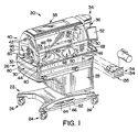
- a thermal support apparatus or patient-support apparatus 20 such as an infant warming device or incubator, includes a base 22, a plurality of castors 24 extending downwardly from base 22, and an infant supporting portion or patient support 26 supported above base 22 as shown in Fig. 1.
- Patient support 26 includes a pedestal 28 coupled to base 22 for vertical movement, a platform tub 30 supported by pedestal 28, and a mattress 32 supported on platform tub 30.
- Mattress 32 has an upwardly facing patient-support surface 33.
- Patient-support apparatus 20 also includes a canopy support arm 34 including a telescoping vertical arm 36 and a horizontal overhead arm 38.
- a canopy 40 is coupled to overhead arm 38 and is positioned to lie above platform tub 30.
- Canopy 40 includes a pair of canopy halves 42 coupled to overhead arm 38 for pivoting movement between a lowered position shown in Fig. 1 and a raised position (not shown).
- a pair of transparent side guard panels 44 and a pair of transparent end guard panels 46 extend upwardly from platform tub 30 as shown in Fig. 1.
- Side guard panels 44 and end guard panels 46 cooperate with canopy halves 42 and overhead arm 38 to provide patient-support apparatus 20 with an isolation chamber.
- Side guard panels 44 may be formed to include a pair of access ports that are normally closed by access door assemblies 48.
- Access door assemblies 48 include door panels 49 that can be opened to allow access to a patient, such as an infant, supported by thermal support apparatus 20 within the isolation chamber.
- Each end guard panel 46 is formed to include at least one U-shaped window and a pass-through grommet 50 is positioned to lie in each U-shaped window. Wires and tubes (not shown) can be routed into the isolation chamber through pass-through grommets 50.
- Patient-support apparatus 20 includes a user interface panel 52 for monitoring various systems that control the temperature and humidity of the isolation chamber and for allowing caregivers to input various control parameters into memory of a control system of patient-support apparatus 20.
- Patient-support apparatus 20 also includes a humidifier module 54 that can be filled with water and inserted into platform tub 30. Heated air is blown through humidifier module 54 and directed into the isolation chamber.
- a tower 56 is positioned to lie in the isolation chamber. Tower 56 supports various sensors 58, such as patient environmental sensors and noise and light sensors, and also provides a return-air path for the air being circulated through the isolation chamber.
- Hinges 60 are provided so that side guard panels 44 and the end guard panel 46 at a foot end of patient support 26 can pivot downwardly away from canopy 40 to provide increased access to the infant supported by patient-support apparatus 20.
- Up and down buttons (not shown) can be pressed to extend and retract vertical arm 36 of canopy support arm 34, thereby raising and lowering, respectively, overhead arm 38 and canopy 40.
- Patient-support apparatus 20 includes an up pedal 62 that can be depressed to raise patient support 26 relative to base 22 and a down pedal 64 that can be depressed to lower patient support 26 relative to base 22.
- Patient-support apparatus 20 also includes a side bumper 66 that protects pedals 62, 64 and other components, such as base 22 and pedestal 28, from inadvertent impact.
- Platform tub 30 is formed to include a handle 68 on each side of canopy support arm 34. Handles 68 can be grasped by a caregiver to maneuver patient-support apparatus 20 during transport.
- Patient-support apparatus 20 includes humidifier module 54 as previously described.
- Humidifier module 54 includes an upper reservoir portion 70 and a lower water heater portion 72 as shown in Fig. 2.
- Heater portion 72 includes a container bottom 74 configured to hold water 76.
- Reservoir portion 70 includes a container top 78 that seats against container bottom 74 to provide humidifier module 54 with a chamber 80. Receipt of water 76 in container bottom 74 subdivides chamber 80 into a water-filled portion 82 and an air-filled portion 84.
- Reservoir portion 70 includes a water reservoir container 86 positioned to lie above container top 78.
- Container 86 has a chamber 88 in which additional water 90 is stored.
- Humidifier module 54 includes a reservoir cover 92 fixed to reservoir container 86 above chamber 88 as shown in Fig. 2.
- a refill door 94 pivotably couples to reservoir container 86 adjacent to an edge of cover 92.
- Refill door 94 is movable relative to container 86 between a closed position, shown in Fig. 2 (in solid), and an opened position, shown in Fig. 2 (in phantom).
- When refill door 94 is in the opened position water can be poured into chamber 88 of reservoir container 86 as shown in Fig. 1.
- Refill door 94 can be moved between the opened and closed positions when humidifier module 54 is separated away from platform tub 30 and when humidifier module 54 is installed in platform tub 30.
- water reservoir container 86 can be filled with water 88 without having to remove humidifier module 54 from platform tub 30.
- Humidifier module 54 includes a control valve 96, shown in Fig. 2, that controls the flow of water from reservoir container 86 to container bottom 74.
- An inlet tube 98 is coupled to flow control valve 96 by an inlet connector 100 and an outlet tube 110 is coupled to flow control valve 96 by an outlet connector 112.
- Container 86 includes a water outlet 114 in fluid communication with chamber 88.
- Inlet tube 98 is coupled to water outlet 114 so that a portion of additional water 88 flows from container 86 through water outlet 114, inlet tube 98, and inlet connector 100 to control valve 96.
- Control valve 96 is actuatable between a closed configuration in which additional water 88 is blocked from flowing into container bottom 74 and an opened configuration in which additional water 88 flows into container bottom 74 to thereby, become water 76.
- Humidifier module 54 includes a heater 116 having a heater pan 118 and a heater pad 120 as shown in Figs. 2, 5, and 7.
- Humidifier module 54 also includes an electrical connector 122, a portion of which is electrically coupled to heater pad 120. Power is supplied to heater pad 120 through electrical connector 122 so that water 76 in water-filled portion 82 of chamber 80 is heated and evaporated into air-filled portion 84 of chamber 80. As water 76 is heated and evaporated, the amount of water 76 in container bottom 74 decreases.
- Humidifier module 54 includes a water level sensor 124, shown in Fig. 2, that is operatively connected to control valve 96.
- sensor 124 When the level of water 76 in container bottom 74 drops to a predetermined level, sensor 124 provides a signal that switches control valve 96 from the closed configuration to the opened configuration so that water 88 from water reservoir container 86 flows through control valve 96 into container bottom 74 as previously described.
- sensor 124 When the level of water 76 rises to a predetermined level, sensor 124 provides a signal that switches control valve 96 from the opened configuration back to the closed configuration so that water 88 is prevented from flowing through control valve 96 into container bottom 74.
- sensor 124 is a commercially available Honeywell Model No. LL 105000 liquid level sensor.
- Heater pad 120 is sandwiched between heater pan 118 and a bottom wall 126 of container bottom 74 as shown best in Figs. 5 and 7. As heater pad 120 heats water 76, bottom wall 126 is also heated.
- Humidifier module 54 includes a locking solenoid 128, shown in Fig. 2, and a temperature sensor (not shown) that is operatively coupled to locking solenoid 128.
- the temperature sensor is positioned to lie between heater pan 118 and heater pad 120 and the temperature sensed by the temperature sensor is correlated to the temperature of bottom wall 126.
- the temperature sensor provides a signal to locking solenoid 128 to extend a locking pin 130 of locking solenoid 128 to a locking position.
- the temperature sensor provides a signal to locking solenoid 128 to retract locking pin 130 to a releasing position.
- Lower water heater portion 72 includes a circuit housing 132 and an electric circuit (not shown) that is contained in an internal compartment of circuit housing 132.
- Control valve 96, heater 116, electrical connector 122, water level sensor 124, and locking solenoid 128 are all coupled to the electric circuit contained in circuit housing 132.
- the electric circuit includes serial port interface circuitry for sending data to and receiving data from a main control circuit of patient-support apparatus 20.
- the electric circuit also includes analog-to-digital conversion circuitry, temperature conditioning circuitry, water fill logic circuitry, humidifier lock-in logic circuitry, temperature lock out comparator circuitry, pan temperature comparator circuitry, humidifier identification code and status circuitry, and voltage regulator circuitry for monitoring and supplying an appropriate level of power to the various components of the electric circuit.
- Heater pad 120 is operated by 120 V AC power and the electric circuit includes both heater control circuitry and optical isolation circuitry that isolates the majority of the electric circuit from the 120 V AC power.
- the electric circuit also includes a set of status LED's, indicated generally by reference numeral 134 shown in Fig. 1.
- Status LED's 134 include a "humidifier connect" LED that, when lit, indicates that humidifier module 54 is connected and receiving power; a low water LED that, when lit, indicates that there is no additional water 88 in water reservoir container 86 and that the level of water 76 is below a predetermined threshold level; and a "lock” LED that, when lit, indicates that locking pin 130 of locking solenoid 128 is in the locking position.
- Humidifier module 54 includes a handle recess 135, shown in Fig. 1, for use by a caregiver to selectively insert humidifier module 54 into and remove humidifier module 54 from platform tub 30 as previously described.
- Platform tub 30 includes a first chamber 136 that is subdivided into a first internal compartment 138 and a second internal compartment 140 by a partition wall 142 as shown in Fig. 3.
- Platform tub 30 also includes a second chamber 144 that is subdivided into a mattress well 146 and an air flow channel 148 by a set of internal walls 150.
- First chamber 136 is separated from second chamber 144 by a pair of transversely extending bulkhead walls 152. Walls 152 are spaced-apart so that inner edges 154 of walls 152 define an opening 156 between first chamber 136 and second chamber 144.
- Patient-support apparatus 20 includes an air or fluid circulation system 158 that circulates air from chamber 136, through opening 156, and into air flow channel 148 as shown in Fig. 3.
- Air circulation system 158 includes a fan 160 and a plurality of heat transfer fins 162 as shown in Fig. 3.
- Fan 160 includes a disk 163, shown in Fig. 9, with a plurality of upwardly extending fan blades 164 appended thereto and a motor (not shown) that is operated to rotate disk 163 and fan blades 164.
- Air circulation system 158 includes a divider or top plate 166 positioned to lie above fan 160 and an air filter 168 positioned to lie above top plate 166 as shown in Fig. 3.
- Top plate 166 divides first internal compartment 138 into an upper air mixing space and a lower air make-up space and top plate 166 is formed to include a fan inlet aperture 170.
- Platform tub 30 includes a cylindrical wall 172, shown in Figs. 4 and 6, that substantially surrounds fan blades 164. Cylindrical wall 172 is formed to include a fan outlet port 174.
- Rotation of fan blades 164 by the motor of fan 160 causes air to be drawn downwardly from the air mixing space through air filter 168 and fan inlet aperture 170 of top plate 166 and into the air make-up space occupied by fan blades 164.
- the air drawn downwardly by fan blades 164 is a mixture of both circulated air, indicated by arrows 176 shown in Fig. 3 (in phantom), and ambient room air, indicated by arrows 178.
- Ambient room air 178 enters internal compartment 138 of platform tub 30 through an air inlet port 180 formed in platform tub 30 adjacent to one of handles 68.
- Circulated air 176 is pulled from the isolation chamber above patient support 26 through a vent opening 182, shown in Fig. 1, formed in tower 56 and then is directed downwardly through an interior region of tower 56 into internal compartment 138 as shown in Fig. 3.
- Air circulation system 158 includes a heater (not shown) that supplies heat to heat transfer fins 162 so that, as the air moves across heat transfer fins 162, the air is warmed to provide a stream of heated air 184.
- the main control circuit of patient-support apparatus 20 includes circuitry for monitoring the temperature in the isolation chamber, circuitry for sensing air flow, circuitry for sensing the rotational speed of fan 160, circuitry for controlling the rotational speed of fan 160, and circuitry for controlling the amount of heat supplied from the heater to heat transfer fins 162.
- the main control circuit is a microprocessor-based circuit having computer software that controls the operation of the various systems of patient-support apparatus including air circulation system 158. Thus, the main control circuit controls the temperature in the isolation chamber by controlling the temperature of heated air 184.
- Platform tub 30 includes an outer wall 186 that is formed to include an opening 188 as shown in Figs. 4 and 6.
- Humidifier module 54 is inserted into compartment 140 through opening 188.
- Patient-support apparatus 20 includes a first external door 190 and a second external door 192, each of which are spring-biased to a position closing respective portions of opening 188 when humidifier module 54 is removed from compartment 140 as shown in Figs. 1 and 3.
- Partition wall 142 is formed to include an opening 194, part of which provides an air outlet port 196 between first internal compartment 138 and second internal compartment 140 and part of which provides an air inlet port 198 between first internal compartment 138 and second internal compartment 140 as shown in Fig. 3.
- Patient-support apparatus 20 includes a pair of internal doors 200, one of which normally closes air outlet port 196 and the other of which normally closes air inlet port 198.
- Internal doors 200 are each coupled to a vertically extending pivot pin 210 as shown in Figs. 4 and 6.
- a torsion spring 212 is also coupled to pivot pin 210 and each door 200 includes a slot 214 that receives a respective end of torsion spring 212. Torsion spring 212 biases each door 200 to a respective closed position as shown in Fig. 4.
- Heat transfer fins 162 are positioned to lie between a pair of first stage walls 216 of platform tub 30 as shown in Fig. 4. Fins 162 and walls 216 are oriented so that air 176, 178 being forced by fan 160 through fan outlet port 174 is directed toward the door 200 that closes air outlet port 196 as shown in Fig. 4.
- Platform tub 30 includes a second stage wall 218 integrally formed with one of first stage walls 216 to provide platform tub 30 with a corner or wall portion 220. Wall portion 220 is transversely spaced apart from pivot pin 210 to define an orifice 222 therebetween.
- Doors 200 are curved so that heated air 184 is circulated from the path defined by heat transfer fins 162 and walls 216, through orifice 222, and into a path defined between the door 200 that closes air inlet port 198 and second stage wall 218.
- Fan 160 further circulates heated air 184 from first internal compartment 138, through opening 156 between edges 154 of walls 152, and into air flow channel 148.
- Humidifier module 54 includes a pair of door openers 224 that are appended to a back wall 226 of container bottom 74 as shown, for example, in Figs. 2 and 3. Door openers 224 are spaced apart to define a pin-receiving space 228 therebetween. A catch ledge 230 extends between door openers 224 adjacent to back wall 226 of container bottom 74.
- Humidifier module 54 includes a latch spring 232 coupled to upper water reservoir portion 70.
- Latch spring 232 includes a bottom catch portion 234 that catches on catch ledge 230 to help secure upper water reservoir portion 70 to lower water heater portion 72.
- Reservoir portion 70 of humidifier module 54 includes a pair of spill damper doors 236, one of which covers an air inlet port 238 of container top 78, shown in Fig. 7, and the other of which covers an air exhaust port (not shown) of container top 78 that is similar to air inlet port 238.
- Each door opener 224 is formed to include a recess 240 for catching water that inadvertently spills out of container bottom 74 between spill damper doors 236 and respective back wall 226 of container bottom 74 during insertion and removal of humidifier module 54 relative to platform tub 30.
- door openers 224 engage respective internal doors 200, as shown in Fig. 4, and pivot doors 200 from their respective closed positions to respective opened positions as shown in Fig. 6.
- pivot pin 210 is received in pin-receiving space 228 between door openers 224.
- door openers 224 hold doors 200 in their opened positions so that distal ends of doors 200 engage wall portion 220 to close orifice 222.
- outer portions of back wall 226 of container bottom 74 and stop portions 250 of container top 78, shown in Figs. 2 and 3 engage respective stop walls 252 of platform tub 30 to prevent insertion of humidifier module 54 past the position shown in Fig. 6.
- a pair of door opener tabs 254 is appended to partition wall 142 above opening 194 and extends therefrom into compartment 140 as shown in Fig. 3.
- One of door opener tabs 254 is positioned to lie over air outlet port 196 and the other of door opener tabs 254 is positioned to lie over air inlet port 198.
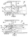
- a top portion of each spill damper door 236 is mounted to container top 78 by a horizontal pivot pin 256 as shown in Figs. 5 and 7.
- tabs 254 engage respective spill damper doors 236 to pivot doors 236 upwardly about respective pivot pins 256 from respective closed positions, shown in Figs. 2, 3, and 5, to respective opened positions, as shown in Fig. 7.
- each door opener 224 is positioned to lie in first internal compartment 138 to hold each respective door 200 in the opened position and a portion of each door opener tab 254 is positioned to lie in chamber 80 to hold each respective spill damper door 236 in the opened position.
- air outlet port 196 of transition wall 142 is adjacent to and mates with air inlet port 238 of humidifier module 54 and air inlet port 198 of transition wall 142 is adjacent to and mates with the air exhaust port of humidifier module 54 when humidifier module 54 is fully inserted into platform tub 30.
- Platform tub 30 includes a top bar 258 that extends across the top boundary of opening 188 formed in outer wall 186 of platform tub 30 as shown in Fig. 3.
- Top bar 258 is formed to include an aperture 260 and an entry notch 262 that extends from the front edge of top bar 258 to aperture 260.
- While humidifier module 54 is fully inserted into platform tub 30 so that doors 200 are in the opened positions, as shown in Figs. 6 and 7, heated air 184 flows from first internal compartment 138 through both air outlet port 196 of partition wall 142 and air inlet port 238 of humidifier module 54 into air-filled portion 84 of chamber 80.
- Heat transfer fins 162 and first stage walls 216 are oriented to direct heated air 184 substantially straight into humidifier module 54 as shown in Fig. 6.
- Container top 78 includes a vertical wall 264, shown in Fig. 6 (in phantom), that partitions air-filled portion 84 of chamber 80 into an air in-flow side and an air out-flow side. Heated air 184 flows around vertical wall 264 and then out of humidifier module 54 and back into first internal compartment 138 through both the air exhaust port of humidifier module 54 and air inlet port 198 of partition wall 142.
- heated air 184 flows through chamber 80 of humidifier module 54, heated air 184 picks up moisture due to the evaporation of water 76 into chamber 80, as previously described.
- heated air 184 is transformed into heated and humidified air 266 while passing through humidifier module 54 as shown in Fig. 6.
- Heated and humidified air 266 exits humidifier module 54 along the out-flow path defined by vertical wall 264 of container top 78 and is directed toward second stage wall 218 of platform tub 30.
- Second stage wall 218 is curved to redirect heated and humidified air 266 from first internal compartment 138, through opening 156 between edges 154 of walls 152, and into air flow channel 148.
- an air fluid stream circulates through platform tub 30 along two different paths depending upon whether humidifier module 54 is inserted into or removed from platform tub 30.
- doors 200 are closed and heated air 184 is circulated from first internal compartment 138 into air flow channel 148 without entering second internal compartment 140.
- doors 200 are opened by door openers 224, spill damper doors 236 are opened by door opener tabs 254, and heated air 184 flows through humidifier module 54 to be transformed into heated and humidified air 266 which, in turn, is circulated back into first internal compartment 138 and then into air flow channel 148.
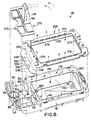
- Patient support 26 includes a platform cover 268 and a compartment cover 270 as shown in Fig. 8.
- Platform cover 268 couples to platform tub 30 so as to cover air flow channel 148.
- Compartment cover 270 couples to platform tub 30 so as to cover first and second internal compartments 138, 140.
- Tower 56 is formed in compartment cover 270.
- compartment cover 270 includes a tab 272 that extends over air inlet port 180.
- Platform cover 268 is formed to include a large rectangular mattress-receiving aperture 274 and a plurality of air vent slots 276 that surround mattress-receiving aperture 272.
- Platform cover 268 further includes an inner lip 278 that seats against internal walls 150 of platform tub 30.
- Platform tub 30 includes a bottom wall 280 to which walls 152 and walls 150 are appended.
- Platform tub 30 also includes a cover plate 330, shown in Fig. 8, that is positioned to lie in a transverse portion of air flow channel 148 between bottom wall 280 and platform cover 268.
- Cover plate 330 includes a first edge 332 positioned to lie adjacent to transverse walls 152 of platform tub 30 and a second edge 334 positioned to lie adjacent to the associated transverse wall 150 of platform tub 30.
- the ends of cover plate 330 are curved and extend from the transverse portion of air flow channel 148 into respective longitudinal portions of air flow channel 148.
- Patient-support apparatus 20 includes top plate 166, shown in Figs.
- Cover plate 330 is substantially coplanar with top plate 166 and a portion of edge 332 of cover plate 330 meets an edge (not shown) of top plate 166 at opening 156.
- the air circulated by fan 160 through fan outlet port 174 passes beneath top plate 166 and through opening 156 into air flow channel 148 beneath cover plate 330.
- Cover plate 330 includes end edges 336 extending between first and second edges 332, 334 as shown in Fig. 8. Fan 160 causes air to pass beneath cover plate 330, past end edges 336, and into the longitudinal portions of air flow channel 148.
- Cover plate 330 is formed to include a pair of bleeder holes 338 which allow some of the air circulating beneath cover plate 330 to move upwardly therethrough into the space above cover plate 330. Some of the air moving upwardly through bleeder holes 328 passes through the air vent slots 276 that are adjacent to tower 56 to provide an air curtain near the head of a patient supported by mattress 32.
- Patient-support apparatus 20 includes a divider wall 340, shown in Fig. 3, that extends between edges 154 of transverse walls 152 above top plate 166 and cover plate 330 to prevent the air that passes upwardly through bleeder holes 338 from moving back into first internal compartment 138 through opening 156.
- a center divider 282 is appended to a bottom surface (not shown) of cover plate 330.
- Center divider 282 extends downwardly from cover plate 330 and is positioned to lie in the transverse portion of air flow channel 148 between the respective wall 150 and opening 156 as shown in Figs. 8 and 9.
- Center divider 282 includes an apex 284 at opening 156 and a pair of curved surfaces 286 extending from apex 284 toward the associated wall 150. Apex 284 cooperates with curved surfaces 286 to split the air passing through opening 156 into two separate air streams which are directed toward opposite sides of platform tub 30.
- Center divider 282 is configured so that the mass flow rate of air in each air stream is substantially equivalent.
- Center divider 282 is also configured so that the air passing through opening 156 into air flow channel 148 does not become turbulent.
- platform tub 30 Internal walls 150 of platform tub 30 are blended together at corners 288.
- platform tub 30 includes outside corner surfaces 290 that confront comers 288 as shown in Fig. 9. Corners 288 and corner surfaces 290 are configured so that the air passing from the transverse head-end portion of air flow channel 148 into the longitudinal portions of air flow channel 148 and the air passing from the longitudinal portions of air flow channel 148 into the transverse foot-end portion of air flow channel 148 does not become turbulent.
- center divider 282 and the various surfaces and walls that bound air flow channel 148 cooperate to ensure that the flow of air through air flow channel 148 is substantially laminar.
- Some of the air circulating through the longitudinal portions of air flow channel 148 passes upwardly through the air vent slots 276 that are adjacent to the longitudinal sides of mattress 32 to provide a pair of spaced-apart air curtains near the sides of the patient supported on mattress 32.
- Some of the air circulating in air flow channel 148 flows from the longitudinal portions thereof into the transverse portion of air flow channel 148 at the foot end of platform tub 30.
- the air in the transverse portion of air flow channel 148 moves upwardly through the air vent slots 276 at the foot end of platform cover 268 to provide an air curtain near the feet of the patient supported on mattress 32.
- bottom wall 280 of platform tub 30 that is positioned to lie in first chamber 136 provides platform tub 30 with a horizontal planar datum surface 328 as shown in Fig. 9.
- Bottom wall 280 ramps upwardly along the path of air flow channel 148 with respect to datum surface 328 to compensate for the air that is lost from air flow channel 148 through the air vent slots 276 thereabove. Ramping bottom wall 280 in this manner causes the velocity at which air exits each air vent slot 276 to more closely approximate a target velocity.
Landscapes
- Health & Medical Sciences (AREA)
- Engineering & Computer Science (AREA)
- Life Sciences & Earth Sciences (AREA)
- Veterinary Medicine (AREA)
- Public Health (AREA)
- General Health & Medical Sciences (AREA)
- Animal Behavior & Ethology (AREA)
- Heart & Thoracic Surgery (AREA)
- Hematology (AREA)
- Biomedical Technology (AREA)
- Anesthesiology (AREA)
- Pulmonology (AREA)
- Emergency Medicine (AREA)
- Chemical & Material Sciences (AREA)
- General Physics & Mathematics (AREA)
- Automation & Control Theory (AREA)
- Physics & Mathematics (AREA)
- Combustion & Propulsion (AREA)
- Mechanical Engineering (AREA)
- General Engineering & Computer Science (AREA)
- Gynecology & Obstetrics (AREA)
- Pediatric Medicine (AREA)
- Pregnancy & Childbirth (AREA)
- Accommodation For Nursing Or Treatment Tables (AREA)
- Air Humidification (AREA)
Claims (44)
- Module humidificateur (54) destiné à un dispositif d'aide à un patient incluant un système de circulation de fluide destiné à mettre en circulation un fluide et une ouverture dans laquelle le module humidificateur est inséré, le module humidificateur comportant un conteneur (80) destiné à contenir de l'eau et fournissant une chambre d'air au-dessus de l'eau, le conteneur comportant une entrée d'air et une sortie d'air destinées à l'air déplacé par le système de circulation de fluide à travers la chambre d'air, un dispositif de chauffage (116) pour chauffer l'eau, un réservoir d'eau (70) destiné à contenir de l'eau supplémentaire, caractérisé en ce qu'il comporte une vanne de commande (96) reliée au réservoir d'eau et reliée au conteneur, la vanne de commande ayant une configuration fermée bloquant l'écoulement d'eau à partir du réservoir d'eau vers le conteneur et la vanne de commande ayant une configuration ouverte permettant l'écoulement d'eau à partir du réservoir d'eau vers le conteneur, et un détecteur de niveau (124) pour détecter le niveau d'eau dans le conteneur et envoyer un signal à la vanne de commande pour déplacer la vanne de commande entre les configurations ouverte et fermée.
- Module humidificateur selon la revendication 1, dans lequel le détecteur de niveau est un détecteur de lumière de réfraction.
- Module humidificateur selon la revendication 1 ou 2, dans lequel le réservoir d'eau est positionné pour être situé au-dessus du conteneur et l'eau supplémentaire s'écoule à partir du réservoir d'eau vers le conteneur lorsque la vanne de commande est dans la configuration ouverte, du fait de la gravité.
- Module humidificateur selon l'une quelconque des revendications précédentes, dans lequel le module comporte au moins une porte anti-déversement et dans lequel la au moins une porte anti-déversement agit comme un tampon destiné à empêcher l'eau chaude chauffée par le dispositif de chauffage de se déverser à l'extérieur du module.
- Module humidificateur selon l'une quelconque des revendications précédentes, dans lequel le dispositif de chauffage est dans une chambre située en dessous du réservoir d'eau.
- Module humidificateur selon l'une quelconque des revendications précédentes, dans lequel le dispositif de chauffage comporte un bac de chauffage qui contient de l'eau et un patin chauffant qui chauffe l'eau et le patin chauffant est relié à une surface de fond du bac de chauffage.
- Module humidificateur selon l'une quelconque des revendications précédentes, comportant de plus un connecteur électrique destiné à être apparié avec un connecteur de service électrique du dispositif d'aide à un patient.
- Dispositif d'aide à un patient comportant une aide à un patient incluant une ouverture dans laquelle est reçu un module humidificateur selon l'une quelconque des revendications précédentes, et un système de mise en circulation de fluide destiné à déplacer de l'air à travers la chambre d'air du module humidificateur.
- Dispositif d'aide à un patient selon la revendication 8, incluant le module humidificateur de la revendication 7 et comportant de plus un connecteur de service électrique relié à l'aide à un patient, adjacent à l'ouverture, et le connecteur électrique du module humidificateur est aligné avec le connecteur de service électrique du dispositif d'aide à un patient et relié automatiquement à celui-ci pour recevoir un courant en provenance de celui-ci lorsque le module humidificateur est inséré dans l'ouverture.
- Dispositif d'aide à un patient selon la revendication 8 ou 9, dans lequel le dispositif d'aide à un patient comporte au moins une porte extérieure qui ferme normalement l'ouverture du dispositif d'aide à un patient et dans lequel la porte est ouverte par l'insertion du module humidificateur dans le dispositif d'aide à un patient.
- Dispositif d'aide à un patient selon la revendication 10, dans lequel la au moins une porte extérieure se ferme automatiquement lorsque le module humidificateur est enlevé de l'ouverture du dispositif d'aide à un patient.
- Dispositif d'aide à un patient selon la revendication 11, lorsqu'elle dépend de la revendication 9, dans lequel la au moins une porte extérieure comporte une porte qui est ouverte par le connecteur électrique du module humidificateur lorsque le module humidificateur est inséré dans l'ouverture de sorte que le connecteur électrique du module humidificateur peut avoir accès au connecteur de service électrique du dispositif d'aide à un patient.
- Dispositif d'aide à un patient selon l'une quelconque des revendications 10 à 12, dans lequel la au moins une porte extérieure comporte une première porte qui pivote autour d'un premier axe dans une première direction lorsque le module humidificateur est inséré à travers l'ouverture et une seconde porte qui pivote autour d'un second axe dans une seconde direction opposée à la première direction lorsque le module humidificateur est inséré à travers l'ouverture.
- Dispositif d'aide à un patient selon la revendication 13, dans lequel le premier axe et le second axe sont tous deux sensiblement verticaux.
- Dispositif d'aide à un patient selon l'une quelconque des revendications 8 à 14, dans lequel une partie importante du réservoir d'eau est positionnée pour être située à l'intérieur de l'aide à un patient alors que le module humidificateur est inséré à travers l'ouverture, le module humidificateur comporte de plus une porte de remplissage qui est positionnée pour être située à l'extérieur de l'aide à un patient lorsque le module humidificateur est inséré à travers l'ouverture, et la porte de remplissage peut être ouverte pour permettre de déverser de l'eau dans le réservoir d'eau.
- Dispositif d'aide à un patient selon l'une quelconque des revendications 8 à 15, dans lequel une partie importante de chacun parmi le réservoir d'eau, le dispositif de chauffage et la chambre d'air passe à travers l'ouverture du dispositif d'aide à un patient lorsque le module humidificateur est inséré dans le dispositif d'aide à un patient.
- Dispositif d'aide à un patient selon l'une quelconque des revendications 8 à 16, dans lequel le dispositif d'aide à un patient comporte un orifice d'entrée d'air et un orifice d'échappement d'air destinés à être appariés en utilisation avec l'entrée d'air et la sortie d'air de l'humidificateur et au moins une porte intérieure qui ferme normalement les orifices d'entrée et de sortie d'air du dispositif d'aide à un patient et dans lequel la porte est ouverte par l'insertion du module humidificateur dans le dispositif d'aide à un patient.
- Dispositif d'aide à un patient selon la revendication 17, dans lequel la au moins une porte intérieure comporte une première porte reliée de manière pivotante à l'aide à un patient et fermant normalement l'orifice d'entrée, une seconde porte reliée de manière pivotante à l'aide à un patient et fermant normalement l'orifice de sortie.
- Dispositif d'aide à un patient selon la revendication 18, dans lequel l'aide à un patient comporte de plus un axe de pivotement et la première et la seconde porte sont toutes deux montées sur l'axe de pivotement pour avoir un mouvement de pivotement.
- Dispositif d'aide à un patient selon la revendication 19, dans lequel l'axe de pivotement s'étend verticalement.
- Dispositif d'aide à un patient selon la revendication 19 ou 20, dans lequel l'aide à un patient comporte une partie de paroi espacée à partir de l'axe de pivotement pour définir un orifice entre elles, le fluide mis en circulation s'écoulant à travers l'orifice lorsque le module humidificateur est enlevé du compartiment, et au moins une parmi les première et seconde portes s'étendant entre la partie de paroi et l'axe de pivotement ferme l'orifice lorsque le module humidificateur est inséré dans l'ouverture.
- Dispositif d'aide à un patient selon l'une quelconque des revendications 18 à 21, dans lequel le module humidificateur comporte des premier et deuxième dispositifs d'ouverture de porte agencés pour venir en prise avec les première et seconde portes respectives et les faire pivoter vers une position ouverte lors de l'insertion du module humidificateur dans le dispositif d'aide à un patient.
- Dispositif d'aide à un patient selon la revendication 22, lorsqu'elle dépend de l'une quelconque des revendications 19 à 21, dans lequel le premier dispositif d'ouverture de porte est espacé du deuxième dispositif d'ouverture de porte pour définir un espace de réception d'axe entre eux, et l'axe de pivotement est positionné pour être situé dans l'espace de réception d'axe lorsque le module humidificateur est inséré dans l'ouverture.
- Dispositif d'aide à un patient selon l'une quelconque des revendications 18 à 23, dans lequel les première et seconde portes pivotent dans des sens opposés l'une vers l'autre en réponse à l'insertion du module humidificateur dans l'ouverture.
- Dispositif d'aide à un patient selon l'une quelconque des revendications 18 à 24, dans lequel le module humidificateur comporte de plus une première porte anti-déversement qui ferme l'entrée du module humidificateur lorsqu'il est enlevé de l'ouverture et une seconde porte anti-déversement qui ferme la sortie du module humidificateur lorsqu'il est enlevé de l'ouverture.
- Dispositif d'aide à un patient selon la revendication 25, dans lequel l'aide à un patient comporte de plus des troisième et quatrième dispositifs d'ouverture de porte agencés pour venir en prise avec les première et seconde portes anti-déversement respectives et les déplacer pour ouvrir l'orifice d'entrée et l'orifice d'échappement du module humidificateur lorsque le module humidificateur est inséré dans l'ouverture.
- Dispositif d'aide à un patient selon la revendication 26, dans lequel les troisième et quatrième dispositifs d'ouverture de porte font pivoter les première et seconde portes anti-déversement vers le haut par rapport au conteneur d'eau lorsque le module humidificateur est inséré dans l'ouverture.
- Dispositif d'aide à un patient selon l'une quelconque des revendications 18 à 27, dans lequel le premier dispositif d'ouverture de porte est positionné pour être situé en dessous de l'entrée du module humidificateur, le deuxième dispositif d'ouverture de porte est positionné pour être situé en dessous de la sortie du module humidificateur, et chacun parmi les premier et deuxième dispositifs d'ouverture de porte est formé pour inclure une cavité destinée à capturer l'eau qui se déverse du conteneur d'eau à travers l'entrée et la sortie.
- Dispositif d'aide à un patient selon l'une quelconque des revendications 8 à 28, dans lequel une aide à un patient a une première chambre, une seconde chambre, et un orifice d'écoulement de fluide entre la première et la seconde chambre, un ventilateur positionné pour être situé dans la première chambre et pouvant être actionné pour déplacer du fluide à travers l'orifice jusqu'à l'intérieur de la seconde chambre, et une structure de profil d'écoulement laminaire annexée à l'aide à un patient dans la seconde chambre et configurée pour maintenir un écoulement laminaire du fluide lorsque le fluide pénètre dans la seconde chambre en provenance de la première chambre.
- Dispositif d'aide à un patient selon la revendication 29, dans lequel l'aide à un patient comporte une paire de parois transversales et une paire de parois longitudinales qui divisent la seconde chambre en un puits formant matelas et un canal qui entoure pratiquement le puits formant matelas et la structure à profil laminaire et configuré pour diriger des quantités sensiblement équivalentes de fluide le long de chacune des parois longitudinales.
- Dispositif d'aide à un patient selon la revendication 30, dans lequel la structure de profil d'écoulement laminaire comporte un diviseur central ayant un sommet situé à l'orifice d'écoulement de fluide et une paire de surfaces incurvées qui s'étendent à partir du sommet et en direction de l'une des parois transversales.
- Dispositif d'aide à un patient selon la revendication 31, comportant de plus une plaque formant couvercle positionnée pour être située dans la seconde chambre et le diviseur central est relié à la plaque formant couvercle et s'étend vers le bas à partir de celle-ci.
- Dispositif d'aide à un patient selon la revendication 29, dans lequel la structure de profil d'écoulement laminaire comporte un diviseur central configuré pour dévier le fluide pour qu'il s'écoule le long de deux trajets séparés dans l'aide à un patient et le diviseur central est configuré de sorte que des quantités sensiblement équivalentes de fluide sont déviées le long de chaque trajet.
- Dispositif d'aide à un patient selon la revendication 33, dans lequel la structure de profil d'écoulement laminaire comporte de plus un sommet au niveau de l'orifice.
- Dispositif d'aide à un patient selon la revendication 34, dans lequel le diviseur central comporte une paire de surfaces incurvées concaves qui s'étendent à partir du sommet à travers un angle d'approximativement 90°.
- Dispositif d'aide à un patient selon l'une quelconque des revendications 33 à 35, comportant de plus une plaque formant couvercle s'étendant au-delà des côtés opposés du diviseur central.
- Dispositif d'aide à un patient selon l'une quelconque des revendications 8 à 36, dans lequel le dispositif d'aide à un patient est formé pour comporter un espace de réception d'axe de blocage, le module humidificateur comporte de plus un axe de blocage, et l'axe de blocage est mobile entre une position bloquante, reçu dans l'espace de réception d'axe de blocage, pour empêcher d'enlever le module humidificateur de l'ouverture, et une position rétractée de libération pour permettre d'enlever le module humidificateur de l'ouverture.
- Dispositif d'aide à un patient selon la revendication 37, comportant de plus un détecteur de température pour détecter la température d'une surface du module humidificateur et un mécanisme de blocage relié au détecteur de température et configuré pour déplacer l'axe de blocage, en réponse à la température détectée par le détecteur de température, entre la position bloquante lorsque la température détectée dépasse une température prédéterminée, et la position de libération lorsque la température détectée est en dessous de la température prédéterminée.
- Dispositif d'aide à un patient selon la revendication 38, dans lequel le mécanisme de blocage comporte un électroaimant relié à l'axe de blocage et l'électroaimant peut être actionné pour déplacer l'axe de blocage entre les positions bloquante et de libération.
- Dispositif d'aide à un patient selon la revendication 38 ou 39, dans lequel le dispositif de chauffage comporte un réservoir de chauffage et un patin chauffant et le détecteur de température est positionné pour être situé entre le réservoir de chauffage et le patin chauffant.
- Dispositif d'aide à un patient selon l'une quelconque des revendications 37 à 40, dans lequel l'aide à un patient comporte un bac, formant plate-forme, dans lequel un compartiment destiné au module humidificateur est formé, et un élément adjacent à une partie du compartiment et l'espace de réception d'axe de blocage est formé dans l'élément.
- Dispositif d'aide à un patient selon la revendication 41, dans lequel l'élément s'étend sur une partie du compartiment, l'espace de réception d'axe de blocage est une échancrure formée dans l'élément, et l'axe de blocage se déplace verticalement vers l'intérieur de l'échancrure et vers l'extérieur de celle-ci.
- Dispositif d'aide à un patient selon l'une quelconque des revendications 37 à 40, dans lequel l'espace de réception d'axe de blocage est une échancrure adjacente à l'ouverture.
- Dispositif d'aide à un patient selon l'une quelconque des revendications 8 à 36, comportant de plus un axe de blocage qui bloque le module humidificateur sur le dispositif d'aide à un patient lorsque la température du dispositif de chauffage dépasse une température seuil, et un indicateur qui indique que l'humidificateur est bloqué sur le dispositif d'aide à un patient.
Applications Claiming Priority (3)
| Application Number | Priority Date | Filing Date | Title |
|---|---|---|---|
| US926383 | 1997-09-09 | ||
| US08/926,383 US6024694A (en) | 1995-09-25 | 1997-09-09 | Humidifier for a thermal support apparatus |
| PCT/US1998/018706 WO1999012513A1 (fr) | 1997-09-09 | 1998-09-09 | Humidificateur pour appareil d'assistance thermique |
Publications (2)
| Publication Number | Publication Date |
|---|---|
| EP1011589A1 EP1011589A1 (fr) | 2000-06-28 |
| EP1011589B1 true EP1011589B1 (fr) | 2003-07-23 |
Family
ID=25453136
Family Applications (1)
| Application Number | Title | Priority Date | Filing Date |
|---|---|---|---|
| EP98944806A Expired - Lifetime EP1011589B1 (fr) | 1997-09-09 | 1998-09-09 | Humidificateur pour appareil d'assistance thermique |
Country Status (9)
| Country | Link |
|---|---|
| US (1) | US6024694A (fr) |
| EP (1) | EP1011589B1 (fr) |
| JP (1) | JP2001515758A (fr) |
| AU (1) | AU9225798A (fr) |
| BR (1) | BR9811646A (fr) |
| CA (1) | CA2302745A1 (fr) |
| DE (1) | DE69816627T2 (fr) |
| NO (1) | NO20001165L (fr) |
| WO (1) | WO1999012513A1 (fr) |
Cited By (1)
| Publication number | Priority date | Publication date | Assignee | Title |
|---|---|---|---|---|
| WO2021127732A1 (fr) * | 2019-12-24 | 2021-07-01 | ResMed Pty Ltd | Appareil permettant d'humidifier un gaz respiratoire |
Families Citing this family (63)
| Publication number | Priority date | Publication date | Assignee | Title |
|---|---|---|---|---|
| JP2001070368A (ja) * | 1999-09-03 | 2001-03-21 | Atom Medical Corp | 保育器用加湿器 |
| JP2001070371A (ja) * | 1999-09-07 | 2001-03-21 | Atom Medical Corp | 保育器 |
| US6880188B1 (en) | 1999-11-15 | 2005-04-19 | Draeger Medical Infant Care, Inc. | Infant care apparatus with movable infant support |
| AU4708401A (en) | 1999-11-15 | 2001-06-25 | Hill-Rom Services, Inc. | Patient-support apparatus |
| US6256454B1 (en) * | 1999-12-11 | 2001-07-03 | Datex- Ohmeda, Inc. | Humidifier for infant warming apparatus |
| WO2001047462A1 (fr) * | 1999-12-23 | 2001-07-05 | Hill-Rom Services, Inc. | Humidificateur destine a un appareil de support pour un patient |
| US6669626B1 (en) | 1999-12-23 | 2003-12-30 | Hill-Rom Services, Inc. | Humidifier for a patient support apparatus |
| US7588029B2 (en) | 2000-03-21 | 2009-09-15 | Fisher & Paykel Healthcare Limited | Humidified gases delivery apparatus |
| US7120354B2 (en) | 2000-03-21 | 2006-10-10 | Fisher & Paykel Healthcare Limited | Gases delivery conduit |
| US7111624B2 (en) | 2000-03-21 | 2006-09-26 | Fisher & Paykel Healthcare Limited | Apparatus for delivering humidified gases |
| US6918389B2 (en) | 2000-03-21 | 2005-07-19 | Fisher & Paykel Healthcare Limited | Breathing assistance apparatus |
| WO2001080804A2 (fr) | 2000-04-21 | 2001-11-01 | Hill-Rom Services, Inc. | Dispositif a securite intrinseque pour un appareil d'assistance pour nourrisson |
| CA2424647C (fr) | 2000-10-16 | 2009-09-08 | Fisher & Paykel Healthcare Limited | Ameliorations apportees a un dispositif utilise pour humidifier des gaz dans des processus medicaux |
| EP1343448B1 (fr) | 2000-12-22 | 2008-09-24 | Draeger Medical Systems, Inc. | Couveuse avec un detecteur d'humidite |
| US20020114360A1 (en) * | 2001-02-20 | 2002-08-22 | Perlman Stephen G. | System and method for processing multiple broadcast multimedia streams |
| CA2443958C (fr) | 2001-04-16 | 2007-06-26 | Hill-Rom Services, Inc. | Support pour bebe : systeme et procede de regulation thermique |
| EP1388106A4 (fr) | 2001-05-15 | 2008-11-19 | Hill Rom Services Inc | Appareil et procede de gestion de donnees sur des patients |
| US7093277B2 (en) * | 2001-05-30 | 2006-08-15 | Digeo, Inc. | System and method for improved multi-stream multimedia transmission and processing |
| US7386129B2 (en) * | 2001-05-30 | 2008-06-10 | Digeo, Inc. | System and method for multimedia content simulcast |
| EP1434546B1 (fr) | 2001-10-05 | 2010-05-19 | Draeger Medical Systems, Inc. | Combinaison dispositif de support pour patient et de chariot d'amarrage |
| CA2464530A1 (fr) | 2001-11-15 | 2003-05-30 | Hill-Rom Services, Inc. | Module d'humidificateur |
| CA2790187C (fr) * | 2002-09-17 | 2015-07-07 | Fisher & Paykel Healthcare Limited | Appareil d'administration de gaz humidifies |
| WO2004026214A1 (fr) | 2002-09-18 | 2004-04-01 | Hill-Rom Services, Inc. | Dispositif de support thermique pour nouveau-nes comprenant un systeme de drain |
| DK2116271T3 (en) | 2002-11-12 | 2016-07-25 | Fisher & Paykel Healthcare Ltd | Apparatus for breathing assistance |
| AU2004266551B2 (en) * | 2003-08-20 | 2009-07-23 | Fisher & Paykel Healthcare Limited | Water chamber for humidifier |
| US7543583B2 (en) * | 2004-07-28 | 2009-06-09 | Hill-Rom Services, Inc. | Forced air vent in siderail |
| CN103143099B (zh) | 2004-08-20 | 2018-04-20 | 菲舍尔和佩克尔保健有限公司 | 用于测量供应给患者的气体的特性的装置 |
| EP2992921B1 (fr) | 2005-08-15 | 2017-09-27 | ResMed Limited | Connecteur interconnectant un humidificateur et un générateur de flux dans un dispositif cpap |
| USD555235S1 (en) * | 2006-06-01 | 2007-11-13 | Aeiomed, Inc. | CPAP blower housing |
| DE102006046466B3 (de) * | 2006-09-29 | 2008-04-10 | Dräger Medical AG & Co. KG | Inkubator oder offene Patientenpflegeeinheit mit automatisch betätigten Seitenscheiben |
| US8365726B2 (en) | 2007-06-07 | 2013-02-05 | Resmed Limited | Tub for humidifier |
| US8079949B2 (en) | 2007-12-05 | 2011-12-20 | Draeger Medical Systems, Inc. | Method and apparatus for providing treatment in a warming device |
| USD601704S1 (en) | 2007-12-05 | 2009-10-06 | Draeger Medical Systems, Inc. | Warming therary device |
| US8342177B2 (en) * | 2008-09-24 | 2013-01-01 | Covidien Lp | Spill resistant humidifier for use in a breathing assistance system |
| WO2010036635A1 (fr) * | 2008-09-29 | 2010-04-01 | Draeger Medical Systems, Inc. | Dispositif de thérapie chauffante comportant un système d’humidification modulaire |
| US20110160520A1 (en) * | 2008-11-07 | 2011-06-30 | Draeger Medical Systems, Inc. | Warming therapy device including pump assembly with integrated heating element |
| CA3177636A1 (fr) | 2011-06-03 | 2012-12-06 | Fisher & Paykel Healthcare Limited | Tubes medicaux et procedes de fabrication |
| DE102011111754A1 (de) * | 2011-08-24 | 2013-02-28 | Thermo Electron Led Gmbh | Brutschrank mit verbesserter Innenraum-Befeuchtung |
| US8733348B2 (en) * | 2011-09-30 | 2014-05-27 | Carefusion 207, Inc. | Humidifying respiratory gases |
| DE102011114900B4 (de) * | 2011-10-05 | 2015-08-27 | Thermo Electron Led Gmbh | Brutschrank mit verbesserter innenraum-befeuchtung |
| GB2541301B (en) | 2012-03-15 | 2017-07-12 | Fisher & Paykel Healthcare Ltd | Respiratory gas humidification system |
| GB2577634B (en) | 2012-04-27 | 2020-09-30 | Fisher & Paykel Healthcare Ltd | Respiratory humidification apparatus |
| CA2871850A1 (fr) | 2012-05-23 | 2013-11-28 | Fisher & Paykel Healthcare Limited | Procede de detection de defaut de trajet d'ecoulement pour un appareil d'assistance respiratoire |
| JP6026144B2 (ja) * | 2012-06-05 | 2016-11-16 | アトムメディカル株式会社 | 保育器 |
| JP5956257B2 (ja) * | 2012-06-25 | 2016-07-27 | アトムメディカル株式会社 | 保育器 |
| CN104955510B (zh) | 2012-11-14 | 2017-05-10 | 费雪派克医疗保健有限公司 | 用于呼吸回路的分区加热 |
| JP6412879B2 (ja) | 2012-12-04 | 2018-10-24 | フィッシャー アンド ペイケル ヘルスケア リミテッド | 医療用チューブおよびその製造方法 |
| GB2583046B8 (en) | 2013-09-13 | 2021-04-28 | Fisher & Paykel Healthcare Ltd | Resilient probe mount for a humidification system |
| US10814091B2 (en) | 2013-10-24 | 2020-10-27 | Fisher & Paykel Healthcare Limited | System for delivery of respiratory gases |
| GB2558102B (en) | 2013-12-20 | 2018-11-28 | Fisher & Paykel Healthcare Ltd | Humidification system connections |
| US10449319B2 (en) | 2014-02-07 | 2019-10-22 | Fisher & Paykel Healthcare Limited | Respiratory humidification system |
| CN111265754B (zh) | 2014-03-17 | 2023-06-06 | 费雪派克医疗保健有限公司 | 用于呼吸系统的医用管 |
| EP3607988B1 (fr) * | 2014-06-03 | 2025-09-10 | Fisher & Paykel Healthcare Limited | Chambre d'humidification pour un appareil de thérapie respiratoire |
| WO2016089224A1 (fr) * | 2014-12-03 | 2016-06-09 | Fisher & Paykel Healthcare Limited | Thérapie par gaz respiratoires |
| CN107106809B (zh) * | 2014-12-18 | 2020-04-21 | 皇家飞利浦有限公司 | 液体腔室分离系统和方法 |
| JP7014717B2 (ja) | 2015-09-09 | 2022-02-01 | フィッシャー アンド ペイケル ヘルスケア リミテッド | 呼吸回路用の区域加熱 |
| SG10202106016TA (en) | 2016-12-07 | 2021-07-29 | Fisher and paykel healthcare ltd | Sensing arrangements for medical devices |
| US11311695B2 (en) | 2016-12-22 | 2022-04-26 | Fisher & Paykel Healthcare Limited | Medical tubes and methods of manufacture |
| JP6300423B1 (ja) * | 2017-01-30 | 2018-03-28 | アトムメディカル株式会社 | 保育器 |
| GB2563013A (en) * | 2017-05-25 | 2018-12-05 | Mom Incubators Ltd | Incubator and method for use |
| KR101937181B1 (ko) * | 2018-07-09 | 2019-01-14 | 주식회사 아베크 | 제균, 살균시스템이 적용된 펫 헬스케어 장치 |
| CN111662527A (zh) * | 2020-05-09 | 2020-09-15 | 惠州市沃瑞科技有限公司 | 一种控湿亲水聚合物及其制备方法和控湿装置 |
| WO2023224069A1 (fr) * | 2022-05-20 | 2023-11-23 | 新コスモス電機株式会社 | Incubateur pour nourrisson, système de soins pour enfants et procédé d'élimination |
Family Cites Families (23)
| Publication number | Priority date | Publication date | Assignee | Title |
|---|---|---|---|---|
| US3187744A (en) * | 1961-01-31 | 1965-06-08 | Air Reduction | Incubator |
| GB947617A (en) * | 1961-11-23 | 1964-01-22 | Oxygenaire London Ltd | Improvements in or relating to incubators for premature infants |
| US3335713A (en) * | 1963-11-05 | 1967-08-15 | Air Shields | Infant incubator |
| US3511162A (en) * | 1969-02-20 | 1970-05-12 | Johnson & Johnson | Apparatus and method for isolating a patient zone |
| BE759595A (nl) * | 1969-12-18 | 1971-04-30 | Pielkenrood Vinitex Bv | Verpleegkast voor zuigelingen of dergelijke |
| US3821947A (en) * | 1971-02-01 | 1974-07-02 | G Schossow | Infant warmer-incubator |
| JPS49122184A (fr) * | 1973-03-28 | 1974-11-21 | ||
| US4121571A (en) * | 1977-01-28 | 1978-10-24 | Pickering Donald E | Transportable life support chamber, method and system |
| CA1155352A (fr) * | 1980-01-14 | 1983-10-18 | James R. Grosholz | Couveuse dotee d'un rideau d'air chaud |
| US4361137B1 (en) * | 1980-01-14 | 1997-02-18 | Air Shields | Incubator having warm air curtain across access opening |
| IL75215A (en) * | 1985-05-16 | 1992-07-15 | Israel Atomic Energy Comm | Infant incubator |
| DE3607575A1 (de) * | 1986-03-07 | 1987-09-10 | Draegerwerk Ag | Inkubator fuer kleinkinder |
| US4796605A (en) * | 1986-07-11 | 1989-01-10 | Atom Kabushiki Kaisha | Incubator |
| US4936824A (en) * | 1987-05-15 | 1990-06-26 | The Boc Group, Inc. | Infant incubator with air curtain |
| US5162038A (en) * | 1989-12-04 | 1992-11-10 | Hill-Rom Company | Infant warmer open bed |
| US5224923A (en) * | 1990-03-26 | 1993-07-06 | Air-Shields, Inc. | Infant incubator |
| CA2039010A1 (fr) * | 1990-03-26 | 1991-09-27 | Kenneth G. Miller | Humidificateur pour les couveuses pour nouveau-nes |
| US5242375A (en) * | 1992-02-27 | 1993-09-07 | Air-Shields, Inc. | Infant incubator and humidifier |
| US5453077A (en) * | 1993-12-17 | 1995-09-26 | Hill-Rom Company, Inc. | Infant thermal support device |
| US5759149A (en) * | 1993-12-17 | 1998-06-02 | Hill-Rom, Inc. | Patient thermal support device |
| US5539854A (en) * | 1994-06-15 | 1996-07-23 | Ohmeda Inc. | Heat controlled humidifier for infant incubator |
| CA2148211C (fr) * | 1994-06-15 | 2006-07-11 | David A. Gloyd | Humidificateur chauffant pour incubateur |
| US5498229A (en) * | 1994-09-09 | 1996-03-12 | Air-Shields, Inc. | Infant radiant warmer |
-
1997
- 1997-09-09 US US08/926,383 patent/US6024694A/en not_active Expired - Lifetime
-
1998
- 1998-09-09 CA CA002302745A patent/CA2302745A1/fr not_active Abandoned
- 1998-09-09 AU AU92257/98A patent/AU9225798A/en not_active Abandoned
- 1998-09-09 DE DE69816627T patent/DE69816627T2/de not_active Expired - Fee Related
- 1998-09-09 JP JP2000510413A patent/JP2001515758A/ja active Pending
- 1998-09-09 BR BR9811646-0A patent/BR9811646A/pt not_active IP Right Cessation
- 1998-09-09 WO PCT/US1998/018706 patent/WO1999012513A1/fr not_active Ceased
- 1998-09-09 EP EP98944806A patent/EP1011589B1/fr not_active Expired - Lifetime
-
2000
- 2000-03-07 NO NO20001165A patent/NO20001165L/no not_active Application Discontinuation
Cited By (1)
| Publication number | Priority date | Publication date | Assignee | Title |
|---|---|---|---|---|
| WO2021127732A1 (fr) * | 2019-12-24 | 2021-07-01 | ResMed Pty Ltd | Appareil permettant d'humidifier un gaz respiratoire |
Also Published As
| Publication number | Publication date |
|---|---|
| AU9225798A (en) | 1999-03-29 |
| BR9811646A (pt) | 2000-08-08 |
| NO20001165L (no) | 2000-05-08 |
| DE69816627D1 (de) | 2003-08-28 |
| DE69816627T2 (de) | 2004-06-17 |
| NO20001165D0 (no) | 2000-03-07 |
| JP2001515758A (ja) | 2001-09-25 |
| WO1999012513A1 (fr) | 1999-03-18 |
| EP1011589A1 (fr) | 2000-06-28 |
| US6024694A (en) | 2000-02-15 |
| CA2302745A1 (fr) | 1999-03-18 |
Similar Documents
| Publication | Publication Date | Title |
|---|---|---|
| EP1011589B1 (fr) | Humidificateur pour appareil d'assistance thermique | |
| KR940008966B1 (ko) | 보육기 | |
| US7335157B2 (en) | Humidifier module | |
| JP3583192B2 (ja) | 保育器用加熱式加湿器 | |
| US8821368B2 (en) | Warming therapy device including modular humidification system | |
| US4846783A (en) | Incubator for infants | |
| EP1520572A2 (fr) | Appareil de support thermique pour patient | |
| JPH0349501B2 (fr) | ||
| GB2323343A (en) | Vehicle rear seat ventilation | |
| WO1993016671A1 (fr) | Incubateur pour bebe et humidifacteur d'air | |
| JPH0422580B2 (fr) | ||
| CN106310475B (zh) | 导气管组件、储液装置、加湿器和呼吸机 | |
| US9095485B2 (en) | Infant incubator | |
| US6669626B1 (en) | Humidifier for a patient support apparatus | |
| US6090036A (en) | Humidifying Mechanism for Incubator | |
| KR20100061115A (ko) | 가습기 | |
| MXPA00002367A (en) | Humidifier for a thermal support apparatus | |
| US5093895A (en) | Humidifier attachable to baseboard radiator | |
| JPH0238737Y2 (fr) | ||
| JPH0319378Y2 (fr) | ||
| GB1576238A (en) | Infant incubator | |
| HK1161074A (en) | Warming therapy device including modular humidification system | |
| HK1161828A (en) | Warming therapy device including modular humidification system | |
| WO2004026214A1 (fr) | Dispositif de support thermique pour nouveau-nes comprenant un systeme de drain | |
| WO2001047462A1 (fr) | Humidificateur destine a un appareil de support pour un patient |
Legal Events
| Date | Code | Title | Description |
|---|---|---|---|
| PUAI | Public reference made under article 153(3) epc to a published international application that has entered the european phase |
Free format text: ORIGINAL CODE: 0009012 |
|
| 17P | Request for examination filed |
Effective date: 20000405 |
|
| AK | Designated contracting states |
Kind code of ref document: A1 Designated state(s): CH DE DK FR GB GR IT LI NL SE |
|
| GRAH | Despatch of communication of intention to grant a patent |
Free format text: ORIGINAL CODE: EPIDOS IGRA |
|
| GRAH | Despatch of communication of intention to grant a patent |
Free format text: ORIGINAL CODE: EPIDOS IGRA |
|
| GRAA | (expected) grant |
Free format text: ORIGINAL CODE: 0009210 |
|
| AK | Designated contracting states |
Designated state(s): CH DE DK FR GB GR IT LI NL SE |
|
| PG25 | Lapsed in a contracting state [announced via postgrant information from national office to epo] |
Ref country code: NL Free format text: LAPSE BECAUSE OF FAILURE TO SUBMIT A TRANSLATION OF THE DESCRIPTION OR TO PAY THE FEE WITHIN THE PRESCRIBED TIME-LIMIT Effective date: 20030723 Ref country code: LI Free format text: LAPSE BECAUSE OF FAILURE TO SUBMIT A TRANSLATION OF THE DESCRIPTION OR TO PAY THE FEE WITHIN THE PRESCRIBED TIME-LIMIT Effective date: 20030723 Ref country code: IT Free format text: LAPSE BECAUSE OF FAILURE TO SUBMIT A TRANSLATION OF THE DESCRIPTION OR TO PAY THE FEE WITHIN THE PRESCRIBED TIME-LIMIT;WARNING: LAPSES OF ITALIAN PATENTS WITH EFFECTIVE DATE BEFORE 2007 MAY HAVE OCCURRED AT ANY TIME BEFORE 2007. THE CORRECT EFFECTIVE DATE MAY BE DIFFERENT FROM THE ONE RECORDED. Effective date: 20030723 Ref country code: FR Free format text: LAPSE BECAUSE OF FAILURE TO SUBMIT A TRANSLATION OF THE DESCRIPTION OR TO PAY THE FEE WITHIN THE PRESCRIBED TIME-LIMIT Effective date: 20030723 Ref country code: CH Free format text: LAPSE BECAUSE OF FAILURE TO SUBMIT A TRANSLATION OF THE DESCRIPTION OR TO PAY THE FEE WITHIN THE PRESCRIBED TIME-LIMIT Effective date: 20030723 |
|
| REG | Reference to a national code |
Ref country code: GB Ref legal event code: FG4D |
|
| REG | Reference to a national code |
Ref country code: CH Ref legal event code: EP |
|
| REF | Corresponds to: |
Ref document number: 69816627 Country of ref document: DE Date of ref document: 20030828 Kind code of ref document: P |
|
| PGFP | Annual fee paid to national office [announced via postgrant information from national office to epo] |
Ref country code: GB Payment date: 20030902 Year of fee payment: 6 |
|
| RAP2 | Party data changed (patent owner data changed or rights of a patent transferred) |
Owner name: HILL-ROM SERVICES, INC. |
|
| PG25 | Lapsed in a contracting state [announced via postgrant information from national office to epo] |
Ref country code: SE Free format text: LAPSE BECAUSE OF FAILURE TO SUBMIT A TRANSLATION OF THE DESCRIPTION OR TO PAY THE FEE WITHIN THE PRESCRIBED TIME-LIMIT Effective date: 20031023 Ref country code: GR Free format text: LAPSE BECAUSE OF FAILURE TO SUBMIT A TRANSLATION OF THE DESCRIPTION OR TO PAY THE FEE WITHIN THE PRESCRIBED TIME-LIMIT Effective date: 20031023 Ref country code: DK Free format text: LAPSE BECAUSE OF FAILURE TO SUBMIT A TRANSLATION OF THE DESCRIPTION OR TO PAY THE FEE WITHIN THE PRESCRIBED TIME-LIMIT Effective date: 20031023 |
|
| PGFP | Annual fee paid to national office [announced via postgrant information from national office to epo] |
Ref country code: DE Payment date: 20031031 Year of fee payment: 6 |
|
| NLT2 | Nl: modifications (of names), taken from the european patent patent bulletin |
Owner name: HILL-ROM SERVICES, INC. |
|
| NLV1 | Nl: lapsed or annulled due to failure to fulfill the requirements of art. 29p and 29m of the patents act | ||
| REG | Reference to a national code |
Ref country code: CH Ref legal event code: PL |
|
| PLBE | No opposition filed within time limit |
Free format text: ORIGINAL CODE: 0009261 |
|
| STAA | Information on the status of an ep patent application or granted ep patent |
Free format text: STATUS: NO OPPOSITION FILED WITHIN TIME LIMIT |
|
| 26N | No opposition filed |
Effective date: 20040426 |
|
| EN | Fr: translation not filed | ||
| PG25 | Lapsed in a contracting state [announced via postgrant information from national office to epo] |
Ref country code: GB Free format text: LAPSE BECAUSE OF NON-PAYMENT OF DUE FEES Effective date: 20040909 |
|
| PG25 | Lapsed in a contracting state [announced via postgrant information from national office to epo] |
Ref country code: DE Free format text: LAPSE BECAUSE OF NON-PAYMENT OF DUE FEES Effective date: 20050401 |
|
| GBPC | Gb: european patent ceased through non-payment of renewal fee |
Effective date: 20040909 |