EP1011900B1 - Schneidwerkzeug - Google Patents
Schneidwerkzeug Download PDFInfo
- Publication number
- EP1011900B1 EP1011900B1 EP98943126A EP98943126A EP1011900B1 EP 1011900 B1 EP1011900 B1 EP 1011900B1 EP 98943126 A EP98943126 A EP 98943126A EP 98943126 A EP98943126 A EP 98943126A EP 1011900 B1 EP1011900 B1 EP 1011900B1
- Authority
- EP
- European Patent Office
- Prior art keywords
- screw
- tool
- tool according
- cutting insert
- slot
- Prior art date
- Legal status (The legal status is an assumption and is not a legal conclusion. Google has not performed a legal analysis and makes no representation as to the accuracy of the status listed.)
- Expired - Lifetime
Links
- 238000003754 machining Methods 0.000 title claims description 4
- 125000006850 spacer group Chemical group 0.000 claims description 14
- 230000000295 complement effect Effects 0.000 claims description 2
- 230000001154 acute effect Effects 0.000 description 2
- 238000006073 displacement reaction Methods 0.000 description 1
- 230000007704 transition Effects 0.000 description 1
Images


Classifications
-
- B—PERFORMING OPERATIONS; TRANSPORTING
- B23—MACHINE TOOLS; METAL-WORKING NOT OTHERWISE PROVIDED FOR
- B23B—TURNING; BORING
- B23B27/00—Tools for turning or boring machines; Tools of a similar kind in general; Accessories therefor
- B23B27/04—Cutting-off tools
-
- Y—GENERAL TAGGING OF NEW TECHNOLOGICAL DEVELOPMENTS; GENERAL TAGGING OF CROSS-SECTIONAL TECHNOLOGIES SPANNING OVER SEVERAL SECTIONS OF THE IPC; TECHNICAL SUBJECTS COVERED BY FORMER USPC CROSS-REFERENCE ART COLLECTIONS [XRACs] AND DIGESTS
- Y10—TECHNICAL SUBJECTS COVERED BY FORMER USPC
- Y10T—TECHNICAL SUBJECTS COVERED BY FORMER US CLASSIFICATION
- Y10T407/00—Cutters, for shaping
- Y10T407/22—Cutters, for shaping including holder having seat for inserted tool
- Y10T407/2272—Cutters, for shaping including holder having seat for inserted tool with separate means to fasten tool to holder
- Y10T407/2282—Cutters, for shaping including holder having seat for inserted tool with separate means to fasten tool to holder including tool holding clamp and clamp actuator
-
- Y—GENERAL TAGGING OF NEW TECHNOLOGICAL DEVELOPMENTS; GENERAL TAGGING OF CROSS-SECTIONAL TECHNOLOGIES SPANNING OVER SEVERAL SECTIONS OF THE IPC; TECHNICAL SUBJECTS COVERED BY FORMER USPC CROSS-REFERENCE ART COLLECTIONS [XRACs] AND DIGESTS
- Y10—TECHNICAL SUBJECTS COVERED BY FORMER USPC
- Y10T—TECHNICAL SUBJECTS COVERED BY FORMER US CLASSIFICATION
- Y10T407/00—Cutters, for shaping
- Y10T407/22—Cutters, for shaping including holder having seat for inserted tool
- Y10T407/2272—Cutters, for shaping including holder having seat for inserted tool with separate means to fasten tool to holder
- Y10T407/2282—Cutters, for shaping including holder having seat for inserted tool with separate means to fasten tool to holder including tool holding clamp and clamp actuator
- Y10T407/2286—Resiliently biased clamp jaw
-
- Y—GENERAL TAGGING OF NEW TECHNOLOGICAL DEVELOPMENTS; GENERAL TAGGING OF CROSS-SECTIONAL TECHNOLOGIES SPANNING OVER SEVERAL SECTIONS OF THE IPC; TECHNICAL SUBJECTS COVERED BY FORMER USPC CROSS-REFERENCE ART COLLECTIONS [XRACs] AND DIGESTS
- Y10—TECHNICAL SUBJECTS COVERED BY FORMER USPC
- Y10T—TECHNICAL SUBJECTS COVERED BY FORMER US CLASSIFICATION
- Y10T407/00—Cutters, for shaping
- Y10T407/22—Cutters, for shaping including holder having seat for inserted tool
- Y10T407/2272—Cutters, for shaping including holder having seat for inserted tool with separate means to fasten tool to holder
- Y10T407/2282—Cutters, for shaping including holder having seat for inserted tool with separate means to fasten tool to holder including tool holding clamp and clamp actuator
- Y10T407/2286—Resiliently biased clamp jaw
- Y10T407/2288—Integral with holder
-
- Y—GENERAL TAGGING OF NEW TECHNOLOGICAL DEVELOPMENTS; GENERAL TAGGING OF CROSS-SECTIONAL TECHNOLOGIES SPANNING OVER SEVERAL SECTIONS OF THE IPC; TECHNICAL SUBJECTS COVERED BY FORMER USPC CROSS-REFERENCE ART COLLECTIONS [XRACs] AND DIGESTS
- Y10—TECHNICAL SUBJECTS COVERED BY FORMER USPC
- Y10T—TECHNICAL SUBJECTS COVERED BY FORMER US CLASSIFICATION
- Y10T407/00—Cutters, for shaping
- Y10T407/25—Cutters, for shaping including cut off tool
Definitions
- the present invention relates to a tool for chip removing machining, preferably for grooving or parting as defined by the preamble of the independent claim.
- WO 96/17706 a tool of the above mentioned type is described.
- the cutting insert and the holder have cooperating grooved surfaces, wherein the upper clamping surfaces are generally V-shaped and the lower clamping surfaces are serrated. At certain moments has happened that the cutting insert has been inserted incorrectly at the lower clamping surface of the insert pocket, i.e. the cutting insert serrations were inserted into the seat but incorrectly positioned in the lateral direction of the cutting insert.
- SU-A1-1720803 is shown a further tool of the above mentioned type wherein the minimum size of the insert pocket is determined.
- One object of the present invention is to provide a rigid tool preferably for thin holders and thin cutting inserts.
- Another object of the present invention is to provide a tool in which the clamping arm is protected from plastic deformation.
- Still another object of the present invention is to provide a tool in which the cutting insert cannot be incorrectly positioned.
- Still another object of the present invention is to provide a tool where twisting of the cutting insert during machining is avoided.
- a tool 10 including a holder 11 and a cutting insert 12.
- the holder 11 is of the type where an arm 13, integrated with the holder, constitutes an upper side 15 of the insert pocket 14.
- the arm is movable about a pivot 27 by means of a screw 17 and a slot 16.
- the slot 16 terminates in the cutting insert pocket.
- the slot extends in the longitudinal direction of the cutting insert, an appropriate distance, beyond the screw 17 influencing the arm 13.
- the screw means 17 as seen in Fig. 3A is provided substantially in the middle of the elongated slot 16.
- the screw 17 fits into a threaded boring 45 which has a center axis CL.
- An abutment surface 34 is provided in connection with the lower border line of the slot 16, wherein the surface 34 constitutes a stop for the cutting insert in its longitudinal direction.
- the upper side 15 has a general convex V-shaped cross-section with flanks converging towards the cutting insert.
- the flanks form an obtuse, internal angle with each other, which lies in the interval 120° to 160°.
- a clearance surface is provided between the flanks in order to avoid a central contact with the cutting insert.
- the arm is intended to clamp the cutting insert against the lower side 19 of the cutting insert pocket.
- the lower side is formed with a number of from each other separate, identical grooves 26, which in cross section describe a substantially trapezoidal path.
- the grooves are elongated and extend along the entire lower side 19.
- the direction F which is the feed direction when the tool is used as a parting tool and the direction L, which is the feed direction when the tool is used as a tool for longitudinal turning are shown in Fig. 2.
- the angle ⁇ between the directions F and L can be 90° ⁇ 15°.
- the groove 26 further has two flanks which connect to the groove bottom, via a sharp or rounded transition. The flanks form an acute angle with each other.
- the cutting insert 12 comprises an upper surface 18, a lower surface 29 as well as side surfaces 20, 21, 22, 23 connecting them, wherein the lines of intersection between the side surfaces 22, 23 and the upper surface 18 form cutting edges 24, 25.
- the cutting insert is preferably somewhat wider than the cutting insert pocket, for the sake of clearance.
- the length of the insert edge 24 is shorter than the height of the cutting insert between upper and lower surfaces 18, 29.
- the upper surface has two flanks which converge towards the lower surface 29 with an external angle substantially corresponding to the above-mentioned internal angle.
- the lower side is formed by a number of from each other separate, substantially, identical ridges 30.
- the ridges form a substantially sinusoidal curve, in cross section, which oscillates about a line.
- the ridges are elongated and extend along the entire lower side 29.
- the ridge 30 has two flanks which touch and connect to a bottom 31. The flanks form an acute angle with each other.
- the tool according to the present invention further comprises an externally threaded sleeve or set screw 40, an annular member or a spacer 41 and a washer 42, all being substantially symmetrically positioned relative to the axis of the screw 17.
- the axis of the screw 17 is substantially perpendicular to the slot 16.
- the set screw 40 is of cylindrical shape and has a flange 43 at its free end which is fitted into a complementary, threaded boring 44 in the holder.
- the set screw flange 43 and a shoulder of the boring defines the maximum size of the insert pocket.
- the spacer 41 is preferably a metallic circular ring which is positioned in the slot 16 around the sleeve 40.
- the width of the slot 16 in mounted position is depicted by E.
- the thickness of the spacer 41 is depicted by T, which is a distance S thinner than the width E.
- the distance or gap S allows the arm 13 to deform elastically to a certain extent during tightening of the screw 17.
- the provision of the washer 42 allows the shank of the screw 17 to come into threaded engagement with the boring in the holder, but will stop the head of the screw from reaching the sleeve 40 during tightening.
- the internal diameter of the spacer 41 is larger than the internal diameter of the washer 42.
- Assembly of the tool according to the present invention is done as follows.
- the spacer 41 is aligned with the center axis CL within the slot 16 on the slot floor 46.
- the spacer is not supposed to project from the slot outside of the tool and it will not extend to or interfere with the insert pocket.
- the set screw 40 is screwn into the boring 44 through the spacer and the upper position of the arm 13 is to be determined.
- the set screw flange 43 abuts the annular shoulder in the arm 13 the arm will be forced to close the slot somewhat.
- a reference insert of the type "Go/No go” is inserted in the pocket and the set screw is tightened until only the "Go" part of the insert can be inserted but not the "No go” part.
- the set screw is preferably provided with a thread lock means to avoid accidental displacement thereof. Then the screw 17 is inserted through the washer 42 and inserted into the boring 45 and tightened somewhat. This is preferably done at the tool manufacturers site. When the screw 17 is untightened and the pocket achieves its maximum size, the cutting insert pocket 14 is widened by releasing induced elastic energy in the arm 13. In doing so, the cutting insert can be aligned with the holder and can be brought into contact such that associated ridges 30 and grooves 26 come into engagement with each other. Subsequently the cutting insert is inserted, which is guided by said engagement, until the insert inner edge surface 23 abuts against the abutment surface 34.
- the screw 17 can be activated such that the flanks of the arm 13 abut against associated flanks on the cutting insert, whereby the ridges are firmly pressed against the grooves.
- the calibrated spacer 41 is used. That is, when the screw 17 is tightened and the insert is firmly clamped, the screw may be further tightened only until the distance S has moved in between the flange 43 and the associated shoulder. In that position the ceiling 47 of the slot abuts the spacer and thus prevents further tightening of the screw.
- the insert is to be replaced or indexed, only the screw 17 is untightened such that the gap S will reappear at the position shown in Fig. 3.
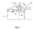
- Fig. 6 is shown an alternative embodiment of a tool 10' according to the present invention, wherein the holder 11' is provided with a separate plate 13' intended to be fastened on the holder 11'.
- the pivot 27' is constituted by two abutment lines or surfaces 48, 49.
- the cutting insert is clamped in the way as described above except that there is no induced elastic energy in the arm. Such energy is then preferably provided by a spring which is applied radially outside and around the spacer.
- the spacer 41 in some cases could be omitted, for example if the arm is very stable. Also if the head of the screw 17 is of larger diameter than shown then the washer 42 can be omitted.
- the tool according to the present invention provides the advantages of safety against plastic deformation of the clamping arm during positioning of the insert in the pocket, optimal locking force on the insert thereby avoiding breakage or permanent distortion of the clamp, and trouble-free locking mechanism also if the locking screw is over-torqued.
Landscapes
- Engineering & Computer Science (AREA)
- Mechanical Engineering (AREA)
- Cutting Tools, Boring Holders, And Turrets (AREA)
- Milling Processes (AREA)
Claims (8)
- Werkzeug für das spanabhebende Bearbeiten, vorzugsweise für das Nutenfräsen und/oder Trennen, mit:dadurch gekennzeichnet, daß das Mittel (40) zum Beschränken der Bewegung des Klemmittels die maximale Größe der Einsatztasche (14) bestimmt.einem Halter (11; 11'), der einen Halterkörper und ein Klemmittel (13; 13') aufweist, die zwischen sich mindestens teilweise einen Schlitz (16) bestimmen, welcher zu einer Schneideinsatztasche (14) gehört,Schraubenmitteln, die mit dem Klemmittel und dem Halterkörper mit einer solchen Ausgestaltung, daß das Klemmittel betätigt wird, in Eingriff treten,einem Schneideinsatz (12; 12'), der eine obere Fläche (18) und eine untere Fläche (29) aufweist und in der Schneideinsatztasche (14) festgeklemmt ist, wobei das Klemmittel und/oder der Werkzeughalter Mittel (40, 41) aufweist zum Beschränken der Bewegung des Klemmittels in mindestens einer Richtung unabhängig von dem Schraubenmittel (17),
- Werkzeug nach Anspruch 1, dadurch gekennzeichnet, daß das Mittel zum Beschränken der Bewegung des Klemmittels eine Hülse (40) mit Außengewinde aufweist, die im wesentlichen symmetrisch relativ zu einer Mittelachse (CL) des Schraubenmittels (17) angeordnet ist.
- Werkzeug nach Anspruch 2, dadurch gekennzeichnet, daß die Hülse (40) eine zylindrische Gestalt und an einem freien Ende einen Flansch (43) hat, der in eine komplementäre Gewindebohrung (44) in dem Halterkörper eingepaßt ist, wobei der Flansch (43) und eine Schulter der Bohrung (44) die maximale Größe der Einsatztasche (14) bestimmen.
- Werkzeug nach einem der Ansprüche 1 bis 3, dadurch gekennzeichnet, daß ein Abstandsmittel (41) in dem Schlitz (16) angeordnet ist, um ein Überklemmen des Klemmittels (13; 13') zu vermeiden.
- Werkzeug nach Anspruch 4, dadurch gekennzeichnet, daß das Abstandsmittel (41) um die Hülse (40) herum angeordnet ist und vorzugsweise ein kreisförmiger, metallischer Ring ist.
- Werkzeug nach einem der vorhergehenden Ansprüche, dadurch gekennzeichnet, daß die Hülse (40) und das Abstandsmittel (41) im wesentlichen symmetrisch relativ zu der Achse (CL) der Schraube (17) angeordnet sind.
- Werkzeug nach einem der vorhergehenden Ansprüche, dadurch gekennzeichnet, daß die Achse (CL) der Schraube (17) im wesentlichen senkrecht zu dem Schlitz (16) ist.
- Werkzeug nach einem der vorhergehenden Ansprüche, dadurch gekennzeichnet, daß das Schraubenmittel (17) im wesentlichen in der Mitte des länglichen Schlitzes (16) vorgesehen ist.
Applications Claiming Priority (3)
| Application Number | Priority Date | Filing Date | Title |
|---|---|---|---|
| SE9703260A SE514254C2 (sv) | 1997-09-10 | 1997-09-10 | Verktyg för spånavskiljande bearbetning |
| SE9703260 | 1997-09-10 | ||
| PCT/SE1998/001524 WO1999012681A1 (en) | 1997-09-10 | 1998-08-26 | Tool for chip removing machining |
Publications (2)
| Publication Number | Publication Date |
|---|---|
| EP1011900A1 EP1011900A1 (de) | 2000-06-28 |
| EP1011900B1 true EP1011900B1 (de) | 2003-04-02 |
Family
ID=20408198
Family Applications (1)
| Application Number | Title | Priority Date | Filing Date |
|---|---|---|---|
| EP98943126A Expired - Lifetime EP1011900B1 (de) | 1997-09-10 | 1998-08-26 | Schneidwerkzeug |
Country Status (7)
| Country | Link |
|---|---|
| US (1) | US6010281A (de) |
| EP (1) | EP1011900B1 (de) |
| JP (1) | JP2001515794A (de) |
| KR (1) | KR100554880B1 (de) |
| DE (1) | DE69812976T2 (de) |
| SE (1) | SE514254C2 (de) |
| WO (1) | WO1999012681A1 (de) |
Families Citing this family (16)
| Publication number | Priority date | Publication date | Assignee | Title |
|---|---|---|---|---|
| SE509339C2 (sv) * | 1994-12-08 | 1999-01-11 | Seco Tools Ab | Verktyg och skär för spånavskiljande bearbetning |
| SE514249C2 (sv) * | 1997-09-10 | 2001-01-29 | Seco Tools Ab | Verktyg för spånavskiljande bearbetning |
| IL126055A (en) * | 1998-09-03 | 2003-03-12 | Iscar Ltd | Holder blade and insert pocket opener |
| SE521491C2 (sv) * | 1999-09-01 | 2003-11-04 | Mircona Ab | Förfarande för låsning av ett skär i ett verktyg där upphöjningar i pressas in i hållarens yta av skärkraften |
| JP2004209615A (ja) * | 2003-01-08 | 2004-07-29 | Mitsubishi Materials Corp | 溝入れバイト及びスローアウェイチップ |
| JP4770297B2 (ja) * | 2004-12-16 | 2011-09-14 | 三菱マテリアル株式会社 | 切削インサートのクランプ機構および切削インサート |
| US7429150B2 (en) * | 2006-05-31 | 2008-09-30 | Kennametal Inc. | Tool holder with spherical contact points |
| JP5289034B2 (ja) * | 2008-12-24 | 2013-09-11 | 京セラ株式会社 | ホルダおよび切削工具並びにそれを用いた切削方法 |
| JP5717885B2 (ja) | 2012-01-30 | 2015-05-13 | 京セラ株式会社 | ホルダおよび切削工具 |
| CN102601403B (zh) * | 2012-03-21 | 2014-07-09 | 株洲钻石切削刀具股份有限公司 | 一种用于槽加工切削刀片的刀夹 |
| EP2703104B1 (de) * | 2012-08-29 | 2015-07-08 | Sandvik Intellectual Property AB | Halteranordnung für einen Schneidwerkzeugeinsatz |
| US9120154B2 (en) * | 2013-02-14 | 2015-09-01 | Iscar, Ltd. | Single-sided square-shaped indexable cutting insert and cutting tool |
| CN104400038A (zh) * | 2014-10-17 | 2015-03-11 | 郑州市钻石精密制造有限公司 | 加工渣浆泵零部件的槽刀 |
| CN112025208A (zh) * | 2019-06-04 | 2020-12-04 | 哈尔滨汽轮机厂有限责任公司 | 一种螺纹套式虎头刀排及加工方法 |
| CN111644644A (zh) * | 2020-05-18 | 2020-09-11 | 成都戴梦迪超硬工具有限责任公司 | 一种既能快速装夹又能重复修磨的带齿纹结构刀具 |
| IL303781B2 (en) * | 2023-06-15 | 2025-07-01 | No Screw Ltd | System and method for holding cutting tools, and cutting tools for working with them |
Family Cites Families (6)
| Publication number | Priority date | Publication date | Assignee | Title |
|---|---|---|---|---|
| US2309410A (en) * | 1941-03-04 | 1943-01-26 | Frank P Miller | Inserted blade cutter |
| DE3909358C2 (de) * | 1989-03-22 | 1994-09-29 | Zinner Gmbh Praezisionswerkzeuge | Spanendes Werkzeug |
| SU1720803A1 (ru) * | 1990-03-11 | 1992-03-23 | Научно-Исследовательская Лаборатория "Карбидные Материалы" | Отрезной резец |
| SE509363C2 (sv) * | 1995-09-25 | 1999-01-18 | Sandvik Ab | Fastspänningsanordning fjör skärplattor samt skärplatta avsedd för dylik anordning |
| US5829923A (en) * | 1996-10-30 | 1998-11-03 | Sandvik, Inc. | Blade-type holder for clamping a cutting insert and an adapter for supporting the holder |
| US5921724A (en) * | 1997-12-18 | 1999-07-13 | Kennametal Inc. | Insert and toolholder for machining operations |
-
1997
- 1997-09-10 SE SE9703260A patent/SE514254C2/sv not_active IP Right Cessation
-
1998
- 1998-08-26 DE DE69812976T patent/DE69812976T2/de not_active Expired - Fee Related
- 1998-08-26 KR KR1020007002480A patent/KR100554880B1/ko not_active Expired - Fee Related
- 1998-08-26 EP EP98943126A patent/EP1011900B1/de not_active Expired - Lifetime
- 1998-08-26 WO PCT/SE1998/001524 patent/WO1999012681A1/en not_active Ceased
- 1998-08-26 JP JP2000510556A patent/JP2001515794A/ja active Pending
- 1998-09-10 US US09/151,097 patent/US6010281A/en not_active Expired - Fee Related
Also Published As
| Publication number | Publication date |
|---|---|
| DE69812976T2 (de) | 2004-02-05 |
| KR20010023806A (ko) | 2001-03-26 |
| DE69812976D1 (de) | 2003-05-08 |
| KR100554880B1 (ko) | 2006-02-24 |
| SE9703260L (sv) | 1999-03-11 |
| US6010281A (en) | 2000-01-04 |
| EP1011900A1 (de) | 2000-06-28 |
| SE514254C2 (sv) | 2001-01-29 |
| JP2001515794A (ja) | 2001-09-25 |
| WO1999012681A1 (en) | 1999-03-18 |
| SE9703260D0 (sv) | 1997-09-10 |
Similar Documents
| Publication | Publication Date | Title |
|---|---|---|
| EP1011900B1 (de) | Schneidwerkzeug | |
| CA1104330A (en) | Clamping mechanism for cutting insert | |
| CN1125696C (zh) | 刀夹和用于固定切削刀片的压板 | |
| US5100268A (en) | Insert clamped tool | |
| EP2178667B1 (de) | Klemmwerkzeughalter | |
| US8556548B2 (en) | Tool holder clamp assembly for cutting inserts and its pressing plate | |
| EP0759826B2 (de) | Werkzeughalter mit spanneinrichtung für schneideinsätzen mit offnungen | |
| JPH0631504A (ja) | インサートとスペーサ部材を具備した切削工具 | |
| EP0398363B1 (de) | Klemmstahlhalter | |
| EP1021266B1 (de) | Werkzeug für spanabhebende bearbeitung | |
| EP1313585B1 (de) | Spannwerkzeughalter | |
| EP0960676B1 (de) | Werkzeug und Spanner für spannabhebende Arbeitung | |
| EP1314502A1 (de) | Drehendes Schneidwerkzeug | |
| JP4283671B2 (ja) | インサート用の回転可能切削工具および固定配列体 | |
| EP0820361B1 (de) | Werkzeughalter zum spannen von schneideinsätzen | |
| EP0751845B1 (de) | Schneidwerkzeugzusammenbau und schneideinsatz | |
| USRE31292E (en) | Clamping mechanism for cutting insert | |
| CA1104332A (en) | Clamping mechanism for cutting insert | |
| CA1104331A (en) | Clamping mechanism for cutting insert |
Legal Events
| Date | Code | Title | Description |
|---|---|---|---|
| PUAI | Public reference made under article 153(3) epc to a published international application that has entered the european phase |
Free format text: ORIGINAL CODE: 0009012 |
|
| 17P | Request for examination filed |
Effective date: 20000218 |
|
| AK | Designated contracting states |
Kind code of ref document: A1 Designated state(s): DE ES FR GB IT SE |
|
| GRAH | Despatch of communication of intention to grant a patent |
Free format text: ORIGINAL CODE: EPIDOS IGRA |
|
| GRAH | Despatch of communication of intention to grant a patent |
Free format text: ORIGINAL CODE: EPIDOS IGRA |
|
| GRAA | (expected) grant |
Free format text: ORIGINAL CODE: 0009210 |
|
| AK | Designated contracting states |
Designated state(s): DE ES FR GB IT SE |
|
| REG | Reference to a national code |
Ref country code: GB Ref legal event code: FG4D |
|
| REF | Corresponds to: |
Ref document number: 69812976 Country of ref document: DE Date of ref document: 20030508 Kind code of ref document: P |
|
| PG25 | Lapsed in a contracting state [announced via postgrant information from national office to epo] |
Ref country code: SE Free format text: LAPSE BECAUSE OF FAILURE TO SUBMIT A TRANSLATION OF THE DESCRIPTION OR TO PAY THE FEE WITHIN THE PRESCRIBED TIME-LIMIT Effective date: 20030702 |
|
| PG25 | Lapsed in a contracting state [announced via postgrant information from national office to epo] |
Ref country code: ES Free format text: LAPSE BECAUSE OF FAILURE TO SUBMIT A TRANSLATION OF THE DESCRIPTION OR TO PAY THE FEE WITHIN THE PRESCRIBED TIME-LIMIT Effective date: 20031030 |
|
| ET | Fr: translation filed | ||
| PLBE | No opposition filed within time limit |
Free format text: ORIGINAL CODE: 0009261 |
|
| STAA | Information on the status of an ep patent application or granted ep patent |
Free format text: STATUS: NO OPPOSITION FILED WITHIN TIME LIMIT |
|
| 26N | No opposition filed |
Effective date: 20040105 |
|
| PGFP | Annual fee paid to national office [announced via postgrant information from national office to epo] |
Ref country code: DE Payment date: 20080912 Year of fee payment: 11 |
|
| PGFP | Annual fee paid to national office [announced via postgrant information from national office to epo] |
Ref country code: IT Payment date: 20080829 Year of fee payment: 11 Ref country code: FR Payment date: 20080818 Year of fee payment: 11 |
|
| PGFP | Annual fee paid to national office [announced via postgrant information from national office to epo] |
Ref country code: GB Payment date: 20080903 Year of fee payment: 11 |
|
| GBPC | Gb: european patent ceased through non-payment of renewal fee |
Effective date: 20090826 |
|
| REG | Reference to a national code |
Ref country code: FR Ref legal event code: ST Effective date: 20100430 |
|
| PG25 | Lapsed in a contracting state [announced via postgrant information from national office to epo] |
Ref country code: FR Free format text: LAPSE BECAUSE OF NON-PAYMENT OF DUE FEES Effective date: 20090831 Ref country code: DE Free format text: LAPSE BECAUSE OF NON-PAYMENT OF DUE FEES Effective date: 20100302 |
|
| PG25 | Lapsed in a contracting state [announced via postgrant information from national office to epo] |
Ref country code: GB Free format text: LAPSE BECAUSE OF NON-PAYMENT OF DUE FEES Effective date: 20090826 |
|
| PG25 | Lapsed in a contracting state [announced via postgrant information from national office to epo] |
Ref country code: IT Free format text: LAPSE BECAUSE OF NON-PAYMENT OF DUE FEES Effective date: 20090826 |