EP1011907B1 - Procede et appareil d'affutage des dents d'une scie a chaine - Google Patents
Procede et appareil d'affutage des dents d'une scie a chaine Download PDFInfo
- Publication number
- EP1011907B1 EP1011907B1 EP98920462A EP98920462A EP1011907B1 EP 1011907 B1 EP1011907 B1 EP 1011907B1 EP 98920462 A EP98920462 A EP 98920462A EP 98920462 A EP98920462 A EP 98920462A EP 1011907 B1 EP1011907 B1 EP 1011907B1
- Authority
- EP
- European Patent Office
- Prior art keywords
- tooth
- teeth
- chain
- saw
- sharpening
- Prior art date
- Legal status (The legal status is an assumption and is not a legal conclusion. Google has not performed a legal analysis and makes no representation as to the accuracy of the status listed.)
- Expired - Lifetime
Links
- 238000000034 method Methods 0.000 title claims description 9
- 230000033001 locomotion Effects 0.000 claims description 10
- 230000000694 effects Effects 0.000 claims description 8
- 230000015572 biosynthetic process Effects 0.000 abstract description 3
- 230000008859 change Effects 0.000 description 2
- 230000018109 developmental process Effects 0.000 description 2
- 238000005755 formation reaction Methods 0.000 description 2
- 239000000463 material Substances 0.000 description 2
- 230000000630 rising effect Effects 0.000 description 2
- 238000004804 winding Methods 0.000 description 2
- 230000008901 benefit Effects 0.000 description 1
- 230000000295 complement effect Effects 0.000 description 1
- 238000005553 drilling Methods 0.000 description 1
- 230000006872 improvement Effects 0.000 description 1
- 230000007794 irritation Effects 0.000 description 1
- 230000007935 neutral effect Effects 0.000 description 1
- 229920003023 plastic Polymers 0.000 description 1
- 239000004033 plastic Substances 0.000 description 1
- 230000009467 reduction Effects 0.000 description 1
- 230000004044 response Effects 0.000 description 1
- 230000001360 synchronised effect Effects 0.000 description 1
- 230000036346 tooth eruption Effects 0.000 description 1
Images

Classifications
-
- B—PERFORMING OPERATIONS; TRANSPORTING
- B23—MACHINE TOOLS; METAL-WORKING NOT OTHERWISE PROVIDED FOR
- B23D—PLANING; SLOTTING; SHEARING; BROACHING; SAWING; FILING; SCRAPING; LIKE OPERATIONS FOR WORKING METAL BY REMOVING MATERIAL, NOT OTHERWISE PROVIDED FOR
- B23D63/00—Dressing the tools of sawing machines or sawing devices for use in cutting any kind of material, e.g. in the manufacture of sawing tools
- B23D63/08—Sharpening the cutting edges of saw teeth
- B23D63/16—Sharpening the cutting edges of saw teeth of chain saws
- B23D63/166—Sharpening the cutting edges of saw teeth of chain saws without removal of the saw chain from the guide bar
- B23D63/168—Sharpening the cutting edges of saw teeth of chain saws without removal of the saw chain from the guide bar the saw chain moving around the guide bar
-
- Y—GENERAL TAGGING OF NEW TECHNOLOGICAL DEVELOPMENTS; GENERAL TAGGING OF CROSS-SECTIONAL TECHNOLOGIES SPANNING OVER SEVERAL SECTIONS OF THE IPC; TECHNICAL SUBJECTS COVERED BY FORMER USPC CROSS-REFERENCE ART COLLECTIONS [XRACs] AND DIGESTS
- Y10—TECHNICAL SUBJECTS COVERED BY FORMER USPC
- Y10T—TECHNICAL SUBJECTS COVERED BY FORMER US CLASSIFICATION
- Y10T83/00—Cutting
- Y10T83/909—Cutter assemblage or cutter element therefor [e.g., chain saw chain]
- Y10T83/917—Having diverse cutting elements
Definitions
- the present invention relates to a method and a device for sharpening the teeth of motor chain saws according to the preambles of claims 1 and 2.
- Users of motor saws are familiar with the necessity of sharpening the teeth on the chain at relatively frequent intervals to maintain satisfactory cutting, and are well aware that this procedure is difficult and time-consuming, or is a source of irritation. By its nature, the problem is particularly familiar to forestry workers.
- the chain saw teeth are filed purely manually by filing with a round file at a filing angle of approximately 30°.
- Chain teeth are in several respects very different from ordinary saw teeth, primarily in having not only an outwardly projecting flank portion, but also an outermost, bent-out top portion, which is to be sharpened from below such that the leading edges of both the flank and the top portion are kept sharp. Therefore, the tooth should be affected by a filing or grinding pressure in a direction away from the root of the tooth, in addition to the force against the flank itself. This influence is liable to cause the treated tooth carrying chain link to tilt outwardly from its position rested against the sword edge, and while this can be 'felt' and accepted by a manual filing it will nevertheless incur problems in connection with automatic sharpening, inasfar as some backing of the treated tooth is required.
- the tooth carrying chain links also have, at the end opposite to and operatively in front of the respective teeth, an outwardly protruding "rider", which is somewhat less protruding than the tooth and has the purpose of delimiting the intrusion of the tooth into the material being sawn and remove the resulting chips.
- riders arranged rather closely in front of the teeth, will to some degree prevent a grinding disc from entering the teeth in a fully ideal manner, which would be by way of a large disc rotating in a plane parallel with the chain carrying link in front of the tooth; in practice, however, it could be sufficient to operate with an inclined position of the plane of rotation, such that the disc edge will enter into the tooth with the disc just passing over the top of the rider.
- the teeth of the saw chains appear with a much longer mutual distance than ordinary saw teeth. Normally there is a number of neutral chain links interposed between the consecutive tooth links, and since the consecutive teeth are layed out (or rather in) to opposite sides, the distance between two similarly oriented teeth will be correspondingly large. Although the chains are made with very high precision, unavoidable tolerances will cause small deviations of the distances referred to. The relevance of this observation will appear from the following.
- a more ideal shape of a rotary grinding or filing tool will be a file rod as first referred to, held against the tooth in exactly the same position as by conventional tooth filing, now only rounded up so as to form a relatively large circular element rising upwardly from the tooth and turned into an angular position relative to the saw sword corresponding to the desired filing angle, i.e. an angle of the magnitude 30° from the direction perpendicularly to the sword.
- the filing ring element in the local area immediately in front of the tooth, will appear practically exactly as a conventional file rod, except for a slight curvature thereof, i.e. the ring element will in no way interfere with the said rider in front of the tooth.
- such means for holding down the riders may be provided even on the ring element itself, viz. as a laterally projecting flange which, during the rotation of the ring element, will steadily and slidingly engage the top of the relevant rider and thus stabilize the tooth.
- the invention in practice, provides for a sharpening system that will be superior to previous proposals.
- the invention comprises a further and extremely important development, viz. based on the finding that the said circular filing/grinding element, without any significant change in the character of the local engagement with the single tooth, can be changed from a circular shape into three-dimensional screw shape, in which it is able to cooperate, simultaneously, with a number of consecutive teeth.
- the distance between the chain saw teeth is relatively long and the filing angle is relatively large, and it has been found that these two conditions enable the design of a "screw file” having at each place a pitch angle corresponding to the desired filing angle and having a phase length equal to the distance between the teeth, without the diameter of this screw being extremely large or small compared with the chain or sword dimensions, this almost amounting to a "lucky coincidence".
- the screw file in being rotated about an axis parallel with the moving direction of the teeth, will thus both sharpen the teeth and urge the teeth forwardly, that is rearwardly relative to their operational movement, in order to sharpen the teeth.
- the required counter pressure on the teeth for the filing/grinding tool to effect the desired result may be established already by the inherent resistance against the saw chain being moved along the sword.
- the teeth of the saw chain can be sharpened by a continous movement, merely by a rotation of the filing/grinding screw element, when the latter is mounted in holding connection with the sword of the chain saw, with its axis of rotation held in parallel with the line of movement of the chain.
- the screw element may be driven at moderate speed, pressing itself against the front side of the teeth and thus forcing the chain rearwardly.
- the sharpening screw element just like the said circular filing or grinding element, may well be provided with the discussed flange member serving to hold down the riders, i.e. the tooth or teeth may be pushed rearwardly without any noticeable tilting, whereby a high quality sharpening is achievable by the fully automatic and continuous operation.
- the said US-A-570, 732 does not take into account the discussed condition with respect to slight variations of the distance between the chain saw teeth.
- the disclosed apparatus is provided with two counter rotating screw files for engaging, at the same time, two saw teeth as laid out to opposite sides in the usual manner, whereby the two screw members will assist each other in pushing the saw blade (band-saw) in its reverse direction, filing or grinding the two teeth simultaneously.
- the distance between the two teeth or any pair of two such teeth has to be exactly the same as the operative distance between the two filing or grinding screws, as in case of a slightly larger distance one tooth will be heavily worked while the pressure on the other tooth is relieved and this tooth not worked effectively, while in case of a slightly shorter distance at least one of the teeth and/or one of the filing screws may be mechanically damaged.
- the discussed system should be laid out so as to work only one tooth at a time and as to ensure that the screw element is ready behind the next (or rather second next) tooth when it gets out of engagement with the just worked tooth. Thereafter and preferably only after the working of all of the teeth laid out to the same side, the screw tool for working the remaining teeth is made operative and the first screw tool is made inoperative. In practice, the tools are simply interchanged.
- the problem is not the distance variations between the teeth of opposite layout, but those between the consecutive teeth of the same type.
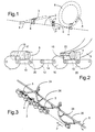
- Fig. 1 is schematically indicated a saw chain 2, appearing with an upstanding saw tooth 4 to be sharpened by filing.
- this would be effected by working the tooth with a straight round file 6 held at a specific angle relative to the transverse direction of the chain e.g. at an angle of some 30° therewith, by reciprocation of the file 6, though preferably with filing pressure only in strokes with and not against the cutting edge.
- Each tooth has a bent-out top portion 3, the leading end of which is also sharpened by the filing. Every second tooth, designated 5, is laid out to the opposite side and should be filed by a file 6' under the same filing angle, but with mirrored orientation relative to the file 6, as shown.
- a convenient, motor driven operation of the ring member 8 is enabled.
- the saw chain 2 is shown in more detail in Fig. 2.
- the teeth 4 and 5 are arranged on link members 10, which are interconnected by three other link members 12, 14 and 16, and in front of the cutting teeth (i.e. to the left) the links 10 are shaped with an upstanding "rider" 18 determining the intrusion depth of the tooth 4, 5 into the material being sawed.
- the file rods 6 or 8 will not in any way interfere with these riders, but in forcing such rods against the teeth 4.5, this will result in a tilting impact on the entire link 10 about its pivot pin 20 underneath the tooth portion 4.5, whereby the tooth may tilt and thus change the ideal filing conditions.
- the rather distance between two consecutive teeth 4 or 5 laid out to the same side could be able to condition that the file ring member 8 could be converted into a screw member 24 which - as shown in Fig. 3 - could extend along the saw chain, with a pitch satisfying the requirements as to the filing angle and also with a winding length corresponding to the distance between two consecutive teeth 4 or 5, without the diameter of this screw member being excessively "small” or "large”.
- the saw chains were never designed with a view to this criterion, and it is to be regarded as a lucky coincidence that the chain teeth will be sharpenable/filable/grindable based on the findings of the present invention.
- Fig. 3 it is shown that the ring member 8 of Figs. 1 and 2, originally arranged in an oblique plane of rotation corresponding to the desired filing angle, is now converted into a screw rod structure 24 axis-parallel with the saw chain 2 and having a pitch corresponding to the desired filing angle of the teeth as well as a winding length corresponding to the distance between two consecutive, similarly oriented teeth 4 or 5, without the required diameter of the screw rod 24 hereby being excessivlely small or large.
- the screw rod member 24 is shown connected to a central rotary a shaft 26 by means of radial pins 28. When the shaft is rotated in the direction R, the screw 24 is rotated so as to effect a movement of the chain 2 in the marked direction P, and at the same time the teeth 4 are filed as desired.
- Fig. 3 merely illustrates the very principle of filing the teeth by means of a screw rod.
- a more rigid structure will be required, and besides, as mentioned above, the screw should not be laid out to work more that a single tooth at a time.
- FIGs. 4 and 5 A practical embodiment of a sharpening apparatus according to the invention is shown in Figs. 4 and 5.
- the apparatus comprises a fixture member 30 having opposed plate portions 32 which, by means of clamp screws 34, can be secured to the sword 36 of a chain saw, with an intermediate bushing portion 38 rising above the top edge thereof.
- the portion 38 has a throughhole 40 for receiving a driving shaft 42 of a cylindrical body 44 provided with a screw formation 46 comprising a plate strip 48 and a further raised, undercut rod member 50.
- the cylinder 44 In its mounted position as shown in Fig. 5, the cylinder 44 is rotatable e.g. by the chuck 52 of a drilling or screwing machine. It will be readily understood that by such a rotation the filing or grinding rod member 50 will be operable to sharpen the teeth 4 successively pushing the chain rearwardly of its working direction.
- Chain saw teeth unlike ordinary saw teeth, are characteristic in being slightly movable relatively to each other and to the their common carrier structure, inasfar as they are displaceable in all three main directions. For a high quality sharpening, therefore, it is required to stabilize the teeth - or the tooth being worked, and of course also to mount the fixture member 30 very accurately on the sword 36. In the following, the conditions in each of the main directions will be discussed separately:
- the fixture member 30 should be mounted such that the lower side of the cylinder is located parallel with and slightly above the path of travel of the top of the teeth 4.5 in order to allow the rod member 50 to properly sharpen the top portions 3.
- the cylinder 44 can be replaced by a calibration body or cylinder 54 having a bottom surface which, in the mounted position, is located slightly closer to the teeth than the bottom side of the cylinder 44, and this calibration body, therefore, can be used for adjusting the fixture body to a correct position, simply by placing the calibration body on the top of the teeth and tightening the clamp screws 34. When thereafter the calibration body is removed and replaced by the cylinder 44, the bottom of the latter will be correctly positioned.
- the screw 46 can be rotated or the chain 2 moved to establish filing contact with a file 50, and from then on the top of the relevant riders 18 will be held down by the screwed plate strip 48, at also discussed in connection with items 18 and 22 of Fig. 2.
- the leading end of the tooth link 10 will be stabilized vertically by the filing engagement itself.
- the tooth links are able to move and tilt somewhat in the cross direction, and for a correct sharpening they should be stabilized in that direction.
- the fixture member 30 comprises a pair of sliding rail members 56, Fig. 4, preferably made of plastics, which are insertable along the upper part of the inner sides of the plate portions 32 so as to more or less closely fill out the gaps between these sides and the row of outer rivet heads 58 of the chain links.
- the screw member 50 should preferably be a little longer that the nominal distance between the relevant teeth, such that the next tooth can be safely gripped even if the tooth distance, due to tolerances, is somewhat longer than the nominal distance. Ideally, therefore in order to allow for both positive and negative tolerances, the leading end E1 of the screw 50 should be able to enter the new tooth link midway between the tooth and the rider thereof, when the worked tooth is just about to be left by the trailing screw end E 2 . This corresponds to the screw having an operative length L as shown in Fig. 5.
- the outer end portion E 2 of the screw 50 is made with a pitch somewhat smaller than the general screw pitch, whereby the driven chain will slow down a little at the end of the engagement, sufficiently to enable the leading end portion E 1 to catch up with the next tooth (V i > V u ) before the first tooth is released from E 2 .
- the end portion E 1 may have the same or even a greater pitch than the general screw pitch, whereby it is achievable that the next tooth is engaged so as to take over the driving of the chain at a speed higher that V u, thus causing the first tooth to be moved forwardly out of engagement with E 2 , i.e. with a "soft" release of this tooth even if the tooth distance deviates from the nominal distance. In this manner the apparatus will be self-adjusting with respect to the said variations in the longitudinal direction.
- the filing or grinding rod 8,50 may be adapted to have a higher or lower efficiency, all according to a desired performance with respect to working pressure and speed, heat development etc.
- the cross section of the filing or grinding rod should not necessarily be "round", if only the side portion cooperating with the teeth has the relevant profilation.
- the riders may be held down directly by the surface of the cylinder 44, in which case it will be relevant to arrange for a screw shaped groove in the cylinder for taking up further projecting tooth portions.
- a very short filing screw portion 60 is arranged for a brief filing of passing teeth 4, while another, complementary filing screw member 62 is arranged for concurrently filing the teeth 5.
- the screw segment 60 can be driven with one direction of rotation by means of a motor shaft 64 of a motor 66, while the screw segment 62 can be driven by an oppositely rotating coaxial shaft 68 from the same motor 66.
- the short screw section 60 and 62 may be provided as integrated parts of a chain saw, i.e. housed inside the outer casing thereof and not being parts of an exterior filing apparatus for intermittent use. In this way the teeth can be sufficiently and currently filed during their normal operation, or at least without the mounting of external equipment.
- the screw file may be arranged at the inside of a surrounding cylinder arranged to be rotated from its outside. The chain may then be worked in being moved through the screw file.
- the geometry of the top portions should preferably be suitably adapted, either as shown in Fig. 9, where the cutting edge 11' is slightly forwardly convex, or as shown in Fig. 10, where the top side is slightly grooved in the longitudinal direction; the latter possibility may be advantageous even for the saw effect of the sharp corner of the cutting edge.
- the invention will comprise such chains which are designed particularly for cooperation with the filing system of the invention.
Landscapes
- Engineering & Computer Science (AREA)
- Mechanical Engineering (AREA)
- Finish Polishing, Edge Sharpening, And Grinding By Specific Grinding Devices (AREA)
- Sawing (AREA)
- Heat Treatment Of Articles (AREA)
- Processing Of Stones Or Stones Resemblance Materials (AREA)
- Soil Working Implements (AREA)
Claims (9)
- Procédé d'affûtage des dents (4, 5) d'une chaíne coupante (2), par lequel une tige d'affûtage (24, 50) est amenée à se déplacer axialement à travers les dents individuelles (4, 5) à un angle d'affûtage souhaité avec la chaíne coupante (2) en restant montée sur son guide-chaíne (36), de telle sorte que le corps d'affûtage (24, 50) effectue un affûtage du bord avant des deux flancs (7) de la dent se projetant de la chaíne coupante (2) et de la partie supérieure de coupe recourbée (3) des dents de la chaíne coupante (4, 5), caractérisé en ce que la tige d'affûtage (24, 50) sous forme d'une vis tridimensionnelle, et ayant la forme d'une structure arrondie dans la direction de la longueur, est positionnée et tournée d'une manière unidirectionnelle de manière à exercer contre les dents (4, 5) une pression d'affûtage orientée latéralement et en poussant en même temps les dents en avant et en ce que la chaíne coupante est guidée pendant l'affûtage par une paire d'éléments de rail de guidage (56).
- Dispositif destiné à effectuer le procédé selon la revendication 1, caractérisé en ce qu'il comprend une tige d'affûtage (24, 50) sous forme d'une vis tridimensionnelle, et ayant la forme d'une structure arrondie dans la direction de la longueur, qui peut être mise en rotation de manière à effectuer, latéralement, l'affûtage souhaité des dents de la chaíne coupante (4, 5) et de sa partie supérieure de coupe recourbée (3) et comprenant une paire d'éléments de rail de guidage (56) pour guider ladite chaíne coupante pendant l'affûtage.
- Dispositif selon la revendication 2, dans lequel la structure de la tige arrondie dans la direction de la longueur a la forme d'un élément formant vis (24, 50) présentant un axe (26) de rotation s'étendant parallèlement à la voie de déplacement des dents (4, 5) le long d'une fraction sélectionnée du passage de la chaíne coupante le long du guide-chaíne (36).
- Dispositif selon la revendication 2 ou 3, comprenant des moyens (22) destinés à la fixation effective de la dent portant les maillons de chaíne (10) par rapport aux déplacements locaux pendant l'affûtage des dents (4, 5).
- Dispositif selon la revendication 4, dans lequel lesdits moyens de fixation comprennent des parties plates (22, 48) associées à la tige (24, 50) dans une position au-dessus adoptée pour que pendant la mise en prise opératoire entre une dent de la chaíne (4, 5) et la barre en mouvement (24, 50), la partie plate (22, 48) viendra en prise par coulissement avec la partie supérieure du cavalier (18) situé sur le même maillon de chaíne (10) que la dent (4, 5).
- Dispositif selon la revendication 5, dans lequel la partie plate (22, 48) est d'une nature d'affûtage modérée.
- Dispositif selon la revendication 3, dans lequel la longueur de l'élément formant vis (24, 50) est légèrement plus longue que la distance nominale entre les dents consécutives (4, 5) devant être affûtées, et dans laquelle le pas de l'élément de vis (24, 50) est plus petit à l'extrémité de sortie de la dent qu'à l'extrémité avant de l'élément formant vis (24, 50).
- Dispositif selon la revendication 3, dans lequel l'élément formant vis (24, 50) est disposé sur un cylindre (44), qui est monté de manière à pouvoir être rotatif dans un élément de fixation (30) devant être fixé sur le guide-chaíne (36), le cylindre (44) pouvant être échangé avec un autre cylindre à miroir (44) pour affûter, avec une direction de rotation opposée, les dents (5) qui sont disposées sur le côté opposé.
- Dispositif selon la revendication 3, intégré dans le logement d'une chaíne coupante.
Applications Claiming Priority (3)
| Application Number | Priority Date | Filing Date | Title |
|---|---|---|---|
| DK58097 | 1997-05-21 | ||
| DK58097 | 1997-05-21 | ||
| PCT/DK1998/000205 WO1998052712A1 (fr) | 1997-05-21 | 1998-05-20 | Procede et appareil d'affutage des dents d'une scie a chaine |
Publications (2)
| Publication Number | Publication Date |
|---|---|
| EP1011907A1 EP1011907A1 (fr) | 2000-06-28 |
| EP1011907B1 true EP1011907B1 (fr) | 2003-07-30 |
Family
ID=8095181
Family Applications (1)
| Application Number | Title | Priority Date | Filing Date |
|---|---|---|---|
| EP98920462A Expired - Lifetime EP1011907B1 (fr) | 1997-05-21 | 1998-05-20 | Procede et appareil d'affutage des dents d'une scie a chaine |
Country Status (10)
| Country | Link |
|---|---|
| US (1) | US6334809B1 (fr) |
| EP (1) | EP1011907B1 (fr) |
| AT (1) | ATE246066T1 (fr) |
| AU (1) | AU7331798A (fr) |
| BR (1) | BR9809861A (fr) |
| CA (1) | CA2291076C (fr) |
| DE (1) | DE69816834T2 (fr) |
| DK (1) | DK1011907T3 (fr) |
| PT (1) | PT1011907E (fr) |
| WO (1) | WO1998052712A1 (fr) |
Families Citing this family (11)
| Publication number | Priority date | Publication date | Assignee | Title |
|---|---|---|---|---|
| JP4510395B2 (ja) * | 2003-03-27 | 2010-07-21 | キヤノン株式会社 | 記録装置 |
| US7900536B2 (en) * | 2006-04-05 | 2011-03-08 | Chain Masters, Inc. | Chain saw sharpener with composite wiskar |
| US8746118B2 (en) | 2008-07-08 | 2014-06-10 | Blount, Inc. | Chain link sharpening method and apparatus |
| DE102009051616B4 (de) * | 2009-06-03 | 2015-06-11 | Timtec Ag | Schärfwinkellehre für Schneidglieder von Kettensägen |
| DE102009039944A1 (de) * | 2009-08-26 | 2011-03-03 | Sanwald, Jürgen | Feiladapter; Verfahren zum Schärfen von Sägeketten |
| DE112010003419A5 (de) * | 2009-08-26 | 2012-08-09 | Jürgen Sanwald | Vorrichtung zum automatischen schärfen von sägeketten, verfahren zum schärfen von sägeketten |
| JP2013508181A (ja) | 2009-10-21 | 2013-03-07 | ブラウント・インコーポレーテッド | バーに設けられる研磨機 |
| USD663602S1 (en) * | 2010-01-21 | 2012-07-17 | Blount, Inc. | Saw chain sharpening stone and holder |
| CN103402718B (zh) | 2011-03-04 | 2015-11-25 | 布楼恩特公司 | 链节磨锐方法和装置 |
| JP5950377B2 (ja) * | 2013-10-02 | 2016-07-13 | 敏行 水上 | ソーチェーンの刃の目立て器 |
| US10265788B2 (en) * | 2015-11-30 | 2019-04-23 | Scott D. Lynn | Chainsaw sharpening device, system, and method |
Family Cites Families (11)
| Publication number | Priority date | Publication date | Assignee | Title |
|---|---|---|---|---|
| US570732A (en) * | 1896-11-03 | Saw-filing machine | ||
| US598268A (en) * | 1898-02-01 | Henry l | ||
| US1634281A (en) * | 1924-03-03 | 1927-07-05 | Oscar H Banker | Band-saw sharpener |
| US1853839A (en) * | 1927-05-23 | 1932-04-12 | Beardsley & Wolcott Mfg Co | Roll |
| US3952615A (en) * | 1975-01-22 | 1976-04-27 | Carlton Company | Saw chain sharpening system |
| US4040314A (en) * | 1975-09-15 | 1977-08-09 | Geeck Joseph S | Chain saw blade sharpening accessory |
| USD257527S (en) * | 1978-01-06 | 1980-11-18 | Pro Sharp Corporation | Saw chain sharpening assembly |
| US4440045A (en) * | 1982-06-01 | 1984-04-03 | Aksamit Frank J | Chain saw sharpener |
| US4727776A (en) * | 1982-08-05 | 1988-03-01 | Elof Granberg | Chain saw sharpening system |
| JPH0525781Y2 (fr) * | 1987-08-13 | 1993-06-29 | ||
| US6005938A (en) | 1996-12-16 | 1999-12-21 | Scientific-Atlanta, Inc. | Preventing replay attacks on digital information distributed by network service providers |
-
1998
- 1998-05-20 US US09/423,668 patent/US6334809B1/en not_active Expired - Fee Related
- 1998-05-20 WO PCT/DK1998/000205 patent/WO1998052712A1/fr not_active Ceased
- 1998-05-20 PT PT98920462T patent/PT1011907E/pt unknown
- 1998-05-20 AU AU73317/98A patent/AU7331798A/en not_active Abandoned
- 1998-05-20 BR BR9809861A patent/BR9809861A/pt not_active IP Right Cessation
- 1998-05-20 DK DK98920462T patent/DK1011907T3/da active
- 1998-05-20 AT AT98920462T patent/ATE246066T1/de not_active IP Right Cessation
- 1998-05-20 DE DE1998616834 patent/DE69816834T2/de not_active Expired - Fee Related
- 1998-05-20 CA CA 2291076 patent/CA2291076C/fr not_active Expired - Fee Related
- 1998-05-20 EP EP98920462A patent/EP1011907B1/fr not_active Expired - Lifetime
Also Published As
| Publication number | Publication date |
|---|---|
| ATE246066T1 (de) | 2003-08-15 |
| DE69816834T2 (de) | 2004-04-22 |
| CA2291076C (fr) | 2006-09-26 |
| AU7331798A (en) | 1998-12-11 |
| CA2291076A1 (fr) | 1998-11-26 |
| BR9809861A (pt) | 2000-06-27 |
| DE69816834D1 (de) | 2003-09-04 |
| WO1998052712A1 (fr) | 1998-11-26 |
| DK1011907T3 (da) | 2003-11-24 |
| PT1011907E (pt) | 2003-12-31 |
| EP1011907A1 (fr) | 2000-06-28 |
| US6334809B1 (en) | 2002-01-01 |
Similar Documents
| Publication | Publication Date | Title |
|---|---|---|
| EP1011907B1 (fr) | Procede et appareil d'affutage des dents d'une scie a chaine | |
| US4078309A (en) | Miter saw | |
| US5127391A (en) | Tile and marble cutting saw apparatus and method | |
| US3183948A (en) | Saw chain | |
| US3744349A (en) | Chain saw sharpener | |
| US4463630A (en) | Chain-saw chain sharpening device | |
| US6463836B1 (en) | Guide for band saws | |
| US2811873A (en) | Chain saw grinding machine | |
| CA2005130C (fr) | Rectifieuse de dents de scies | |
| US3717051A (en) | Saw chain depth gauge grinder | |
| US4815350A (en) | Circular saw machine | |
| JP2784424B2 (ja) | 卓上切断機の下限位置設定装置 | |
| US4961287A (en) | Wood jointer and planer blade sharpening holder | |
| US5033333A (en) | Saw chain grinding machine | |
| US20020119739A1 (en) | Key duplication attachment device for rotary tool with profiled abrasive cutter | |
| US4987704A (en) | Plunge jointer for planer knives | |
| US5000061A (en) | Dressing apparatus for grinding wheels | |
| US6164161A (en) | Band saw blade sharpener | |
| WO1996000627A9 (fr) | Procede et agencement pour aiguiser des chaines de scies, ou une chaine qui se deplace d'une maniere continue provoque le mouvement transversal d'une ou de plusieurs limes | |
| US5031482A (en) | Saw chain grinding machine | |
| US3079815A (en) | Boring head | |
| CN214185551U (zh) | 一种切割质量好的自动锯床 | |
| US3938796A (en) | Workpiece location apparatus | |
| KR200395499Y1 (ko) | 목공 공구용 칼날의 연마각도 조절장치 | |
| JPS5919628A (ja) | 荒切り加工機 |
Legal Events
| Date | Code | Title | Description |
|---|---|---|---|
| PUAI | Public reference made under article 153(3) epc to a published international application that has entered the european phase |
Free format text: ORIGINAL CODE: 0009012 |
|
| 17P | Request for examination filed |
Effective date: 19991202 |
|
| AK | Designated contracting states |
Kind code of ref document: A1 Designated state(s): AT BE CH DE DK ES FI FR GB GR IE IT LI NL PT SE |
|
| 17Q | First examination report despatched |
Effective date: 20010813 |
|
| GRAH | Despatch of communication of intention to grant a patent |
Free format text: ORIGINAL CODE: EPIDOS IGRA |
|
| GRAH | Despatch of communication of intention to grant a patent |
Free format text: ORIGINAL CODE: EPIDOS IGRA |
|
| GRAH | Despatch of communication of intention to grant a patent |
Free format text: ORIGINAL CODE: EPIDOS IGRA |
|
| GRAA | (expected) grant |
Free format text: ORIGINAL CODE: 0009210 |
|
| AK | Designated contracting states |
Designated state(s): AT BE CH DE DK ES FI FR GB GR IE IT LI NL PT SE |
|
| PG25 | Lapsed in a contracting state [announced via postgrant information from national office to epo] |
Ref country code: NL Free format text: LAPSE BECAUSE OF FAILURE TO SUBMIT A TRANSLATION OF THE DESCRIPTION OR TO PAY THE FEE WITHIN THE PRESCRIBED TIME-LIMIT Effective date: 20030730 Ref country code: FI Free format text: LAPSE BECAUSE OF FAILURE TO SUBMIT A TRANSLATION OF THE DESCRIPTION OR TO PAY THE FEE WITHIN THE PRESCRIBED TIME-LIMIT Effective date: 20030730 Ref country code: BE Free format text: LAPSE BECAUSE OF FAILURE TO SUBMIT A TRANSLATION OF THE DESCRIPTION OR TO PAY THE FEE WITHIN THE PRESCRIBED TIME-LIMIT Effective date: 20030730 |
|
| REG | Reference to a national code |
Ref country code: GB Ref legal event code: FG4D |
|
| REG | Reference to a national code |
Ref country code: CH Ref legal event code: EP |
|
| REG | Reference to a national code |
Ref country code: IE Ref legal event code: FG4D |
|
| REF | Corresponds to: |
Ref document number: 69816834 Country of ref document: DE Date of ref document: 20030904 Kind code of ref document: P |
|
| PG25 | Lapsed in a contracting state [announced via postgrant information from national office to epo] |
Ref country code: GR Free format text: LAPSE BECAUSE OF FAILURE TO SUBMIT A TRANSLATION OF THE DESCRIPTION OR TO PAY THE FEE WITHIN THE PRESCRIBED TIME-LIMIT Effective date: 20031030 |
|
| PG25 | Lapsed in a contracting state [announced via postgrant information from national office to epo] |
Ref country code: ES Free format text: LAPSE BECAUSE OF FAILURE TO SUBMIT A TRANSLATION OF THE DESCRIPTION OR TO PAY THE FEE WITHIN THE PRESCRIBED TIME-LIMIT Effective date: 20031110 |
|
| REG | Reference to a national code |
Ref country code: CH Ref legal event code: NV Representative=s name: MICHELI & CIE INGENIEURS-CONSEILS |
|
| REG | Reference to a national code |
Ref country code: SE Ref legal event code: TRGR |
|
| REG | Reference to a national code |
Ref country code: DK Ref legal event code: T3 |
|
| NLV1 | Nl: lapsed or annulled due to failure to fulfill the requirements of art. 29p and 29m of the patents act | ||
| ET | Fr: translation filed | ||
| PLBE | No opposition filed within time limit |
Free format text: ORIGINAL CODE: 0009261 |
|
| STAA | Information on the status of an ep patent application or granted ep patent |
Free format text: STATUS: NO OPPOSITION FILED WITHIN TIME LIMIT |
|
| 26N | No opposition filed |
Effective date: 20040504 |
|
| PG25 | Lapsed in a contracting state [announced via postgrant information from national office to epo] |
Ref country code: IT Free format text: LAPSE BECAUSE OF NON-PAYMENT OF DUE FEES Effective date: 20050520 |
|
| PGFP | Annual fee paid to national office [announced via postgrant information from national office to epo] |
Ref country code: AT Payment date: 20071114 Year of fee payment: 10 Ref country code: CH Payment date: 20071116 Year of fee payment: 10 |
|
| PGFP | Annual fee paid to national office [announced via postgrant information from national office to epo] |
Ref country code: GB Payment date: 20071117 Year of fee payment: 10 Ref country code: FR Payment date: 20071130 Year of fee payment: 10 |
|
| PGFP | Annual fee paid to national office [announced via postgrant information from national office to epo] |
Ref country code: PT Payment date: 20071114 Year of fee payment: 10 |
|
| REG | Reference to a national code |
Ref country code: PT Ref legal event code: MM4A Free format text: LAPSE DUE TO NON-PAYMENT OF FEES Effective date: 20081120 |
|
| REG | Reference to a national code |
Ref country code: CH Ref legal event code: PL |
|
| GBPC | Gb: european patent ceased through non-payment of renewal fee |
Effective date: 20080520 |
|
| PG25 | Lapsed in a contracting state [announced via postgrant information from national office to epo] |
Ref country code: PT Free format text: LAPSE BECAUSE OF NON-PAYMENT OF DUE FEES Effective date: 20081120 Ref country code: LI Free format text: LAPSE BECAUSE OF NON-PAYMENT OF DUE FEES Effective date: 20080531 Ref country code: CH Free format text: LAPSE BECAUSE OF NON-PAYMENT OF DUE FEES Effective date: 20080531 |
|
| PGFP | Annual fee paid to national office [announced via postgrant information from national office to epo] |
Ref country code: DE Payment date: 20081128 Year of fee payment: 11 |
|
| REG | Reference to a national code |
Ref country code: IE Ref legal event code: MM4A |
|
| PG25 | Lapsed in a contracting state [announced via postgrant information from national office to epo] |
Ref country code: AT Free format text: LAPSE BECAUSE OF NON-PAYMENT OF DUE FEES Effective date: 20080520 |
|
| REG | Reference to a national code |
Ref country code: FR Ref legal event code: ST Effective date: 20090119 |
|
| PGFP | Annual fee paid to national office [announced via postgrant information from national office to epo] |
Ref country code: SE Payment date: 20081201 Year of fee payment: 11 |
|
| PG25 | Lapsed in a contracting state [announced via postgrant information from national office to epo] |
Ref country code: IE Free format text: LAPSE BECAUSE OF NON-PAYMENT OF DUE FEES Effective date: 20080520 Ref country code: FR Free format text: LAPSE BECAUSE OF NON-PAYMENT OF DUE FEES Effective date: 20080602 |
|
| PG25 | Lapsed in a contracting state [announced via postgrant information from national office to epo] |
Ref country code: GB Free format text: LAPSE BECAUSE OF NON-PAYMENT OF DUE FEES Effective date: 20080520 |
|
| PGFP | Annual fee paid to national office [announced via postgrant information from national office to epo] |
Ref country code: IE Payment date: 20071116 Year of fee payment: 10 |
|
| PGFP | Annual fee paid to national office [announced via postgrant information from national office to epo] |
Ref country code: DK Payment date: 20091130 Year of fee payment: 12 |
|
| PG25 | Lapsed in a contracting state [announced via postgrant information from national office to epo] |
Ref country code: DE Free format text: LAPSE BECAUSE OF NON-PAYMENT OF DUE FEES Effective date: 20091201 |
|
| REG | Reference to a national code |
Ref country code: DK Ref legal event code: EBP |
|
| PG25 | Lapsed in a contracting state [announced via postgrant information from national office to epo] |
Ref country code: DK Free format text: LAPSE BECAUSE OF NON-PAYMENT OF DUE FEES Effective date: 20100531 |
|
| PG25 | Lapsed in a contracting state [announced via postgrant information from national office to epo] |
Ref country code: SE Free format text: LAPSE BECAUSE OF NON-PAYMENT OF DUE FEES Effective date: 20090521 |
|
| PGFP | Annual fee paid to national office [announced via postgrant information from national office to epo] |
Ref country code: IT Payment date: 20071128 Year of fee payment: 10 |
|
| PGRI | Patent reinstated in contracting state [announced from national office to epo] |
Ref country code: IT Effective date: 20110616 |
|
| PGRI | Patent reinstated in contracting state [announced from national office to epo] |
Ref country code: IT Effective date: 20110616 |