EP1012068B1 - Dispositif de stockage d'un liquide, notamment d'un concentre pouvant etre dilue, destine a fonctionner avec un element de vaporisation - Google Patents
Dispositif de stockage d'un liquide, notamment d'un concentre pouvant etre dilue, destine a fonctionner avec un element de vaporisation Download PDFInfo
- Publication number
- EP1012068B1 EP1012068B1 EP98913707A EP98913707A EP1012068B1 EP 1012068 B1 EP1012068 B1 EP 1012068B1 EP 98913707 A EP98913707 A EP 98913707A EP 98913707 A EP98913707 A EP 98913707A EP 1012068 B1 EP1012068 B1 EP 1012068B1
- Authority
- EP
- European Patent Office
- Prior art keywords
- channel
- top wall
- spray
- liquid
- wall
- Prior art date
- Legal status (The legal status is an assumption and is not a legal conclusion. Google has not performed a legal analysis and makes no representation as to the accuracy of the status listed.)
- Expired - Lifetime
Links
- 239000007921 spray Substances 0.000 title claims abstract description 63
- 235000008504 concentrate Nutrition 0.000 title claims abstract description 27
- 239000012141 concentrate Substances 0.000 title claims abstract description 27
- 239000007788 liquid Substances 0.000 title claims abstract description 21
- 235000020354 squash Nutrition 0.000 title claims abstract description 5
- 239000003599 detergent Substances 0.000 claims abstract description 5
- 238000006073 displacement reaction Methods 0.000 claims abstract description 5
- 238000000034 method Methods 0.000 claims description 4
- XLYOFNOQVPJJNP-UHFFFAOYSA-N water Substances O XLYOFNOQVPJJNP-UHFFFAOYSA-N 0.000 description 6
- 239000003153 chemical reaction reagent Substances 0.000 description 4
- 239000002994 raw material Substances 0.000 description 3
- 239000000126 substance Substances 0.000 description 3
- 239000011888 foil Substances 0.000 description 2
- 239000002184 metal Substances 0.000 description 2
- 239000000443 aerosol Substances 0.000 description 1
- 238000007865 diluting Methods 0.000 description 1
- 239000002917 insecticide Substances 0.000 description 1
- 235000014666 liquid concentrate Nutrition 0.000 description 1
- 239000011344 liquid material Substances 0.000 description 1
- 238000004519 manufacturing process Methods 0.000 description 1
- 230000004048 modification Effects 0.000 description 1
- 238000012986 modification Methods 0.000 description 1
- 238000007789 sealing Methods 0.000 description 1
- 229920002994 synthetic fiber Polymers 0.000 description 1
Images


Classifications
-
- B—PERFORMING OPERATIONS; TRANSPORTING
- B05—SPRAYING OR ATOMISING IN GENERAL; APPLYING FLUENT MATERIALS TO SURFACES, IN GENERAL
- B05B—SPRAYING APPARATUS; ATOMISING APPARATUS; NOZZLES
- B05B11/00—Single-unit hand-held apparatus in which flow of contents is produced by the muscular force of the operator at the moment of use
- B05B11/0005—Components or details
- B05B11/0078—Arrangements for separately storing several components
-
- B—PERFORMING OPERATIONS; TRANSPORTING
- B05—SPRAYING OR ATOMISING IN GENERAL; APPLYING FLUENT MATERIALS TO SURFACES, IN GENERAL
- B05B—SPRAYING APPARATUS; ATOMISING APPARATUS; NOZZLES
- B05B11/00—Single-unit hand-held apparatus in which flow of contents is produced by the muscular force of the operator at the moment of use
- B05B11/01—Single-unit hand-held apparatus in which flow of contents is produced by the muscular force of the operator at the moment of use characterised by the means producing the flow
- B05B11/10—Pump arrangements for transferring the contents from the container to a pump chamber by a sucking effect and forcing the contents out through the dispensing nozzle
- B05B11/1042—Components or details
- B05B11/1052—Actuation means
- B05B11/1056—Actuation means comprising rotatable or articulated levers
- B05B11/1057—Triggers, i.e. actuation means consisting of a single lever having one end rotating or pivoting around an axis or a hinge fixedly attached to the container, and another end directly actuated by the user
Definitions
- the present invention relates to a device for storing a liquid, particularly a dilutable concentrate such as a detergent concentrate or the like, which device is co-operable with a spray dispenser bottle and a spray dispenser head which together form a spray dispenser; to a spray dispenser comprising such a device and to a method for introducing a liquid concentrate, for example, into a spray dispenser bottle.
- a dilutable concentrate such as a detergent concentrate or the like
- the US patent 5,529,216 discloses a chemical reservoir mountable in the neck of a spray bottle dispenser for replenishing the active chemical reagent solution to be sprayed from the spray bottle dispenser. Accordingly, once the initial solution has been used up, the consumer need only refill the spray bottle with water, whereafter the chemical concentrate carried within the chemical reservoir is opened mixed with the water to provide a use solution.
- US patent 5,529,216 teaches a reservoir cartridge having a pierceable, metal foil upper wall and pierceable plastic lower wall.
- the concentrate contained herein is released into a spray container bottle, by means of a needle member associated with a spray head, which is pushed through the upper metal foil wall and lower plastic wall of the reservoir cartridge to rupture these, on assembling the spray dispenser, whereby concentrate held therein is released into the spray bottle container through the ruptured lower wall of the cartridge.
- a disadvantage with this cartridge is that on piercing the lower wall, concentrate is not released at a sufficiently acceptable rate to provide quickly a use solution.
- This needle member doubles as a down-tube for the spray head for transmitting liquid from the spray bottle to the spray head.
- EP-A-0 606 672 discloses a system for diluting and dispensing liquid material including a rigid cartridge containing concentrated liquid, which cartridge is placed in the interior of the upper mouth of a bottle containing water. Said cartridge is opened at the bottom side thereof by screwing an atomizer onto a threaded mouth piece of the bottle, so that the concentrated liquid present in the rigid cartridge is released into the water. Further cartridge-like devices for use in recharging a chemical reagent solution in spray dispenser bottles, are known from the US patent 3,655,096 and the German patent document DE 3535986.
- An object of the present invention is to provide a device which substantially overcomes all of these problems.
- a spray dispenser assembly comprising a spray dispenser head, a device as described above, and a spray container, the device being mounted between the spray dispenser head and the spray container.
- a method of introducing a liquid, particularly a concentrate, into a spray container in order to provide a use solution said method being further described in claim 11.
- the inventors have found that a considerable saving in raw materials is made utilizing a device according to the present invention.
- the device acccrding to the present invention is particularly easy to fill in an efficient way with liquid.
- the device itself comprises the release means for releasing liquid from the reservoir area, this liquid release is easily and efficiently carried out and no additional cooperating features need be associated with either a spray head or spray container to open the device.
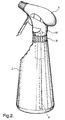
- An assembly 1 (figure 1) comprises a spray bottle dispenser 2, a device 4, in the form of a cartridge, and a spray head 6 having a down tube 8 connected thereto.
- the cartridge 4 has a lip section 10 protruding outwardly from a top wall 12.
- the top wall 12 is provided with an opening 14.
- the cartridge 4 is inserted into a neck section 16 of the bottle 2 (see figure 2) so that the cartridge 4 is suspended by the lip section 10 (see figure 2).
- the spray head 6 is subsequently screwed onto the neck section 16 of the bottle, the down tube 8 of the spray head 6 extending through a channel (see later) continuous with the top wall opening 14 of the cartridge 4 to terminate in the bottle 2 (see figure 2, figure 3a and 3b).
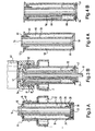
- the cartridge 4 (see figures 3a and 3b), comprises a side wall 18, integral with the lip section 10 and flexible top wall 12.
- Top wall opening 14 is continuous with a channel 20 extending through the cartridge 4, which channel 20 terminates in a bottom channel opening 22. As shown in figures 1 and 2, this channel 20 can receive a down tube 8 associated with the spray head.
- the side wall 18 and channel 20 define a reservoir area 32, sealed at one end of the device 4 by the flexible top wall 12 and at the other end of the device by a rigid bottom wall 24, extending from the bottom channel opening 22 to the side wall 18.
- the bottom wall 24 comprises a first elongated part 26 arranged adjacent to the channel 20, a transverse piece 28 extending from said elongated part 26 to a downwardly extending sealing part 30 arranged adjacent to the side wall 18.
- the down tube 8 of the spray head 6 is inserted into opening 14 and pushed through the channel 20 (see figures 3A and 3B).
- the now empty concentrate cartridge 4 can be simply removed, and following refilling of the spray bottle 2 with water, replaced with a new, fully charged concentrate cartridge 4.
- An embodiment of the invention as shown in figures 4a and 4b comprises a side wall 50 having an upper lip 52, an upper opening 54 continuous with a channel 56 which terminates in a lower opening 58.
- a top wall section 60 extends between the lip 52 and up and over the channel 56, to terminate at the edge channel opening 54.
- This upper wall section 60 is substantially rigid, having an extended support part 62 arranged adjacent to the channel 56.
- a substantially rigid lower wall 64 extends downwardly from the channel 56 to the outer wall 50.
- the channel 56, the lower wall 64 and the side wall 50 are integral, i.e. they consist of one piece of preferably synthetic material.
- the outer wall 50 and the channel 56 define a concentrate reservoir area 66.
- the lower wall 64 is more securely attached to the channel 56 than the outer wall 50.
- the opening 54 extends in the sealed arrangement of the device (figure 4a) above the upper, outer lip 52.
- the upper neck section of a down tube presses down into the opening 54 whereby the channel 56 and upper wall 60 of the cartridge are pushed down with respect to the side wall 50, whereby in turn the seal between the lower wall 64 and the side wall 50 is broken, whereafter the concentrate within the cartridge is released, through opening 69, i.e. on displacement of the channel 56 with respect to the outer wall 50, since the lower wall 64 is more weakly integrally attached to the outer wall 50 than the channel 56, the lower wall 64 ruptures at its juncture with the outer wall 50, due to the rigidity of the lower wall 64, whereby an opening is created (figure 4b), wherethrough concentrate is released into the dispenser.
- top wall section 70 has a pushing section 72 integral therewith, which extends downwardly adjacent to the side wall 74 from the top of the cartridge to the bottom thereof, in order to contact, at one side, the lower wall 76 where this is sealed with the side wall 74. Accordingly on pushing down of the channel, this moves downwardly relative to the outer wall, whereby the top wall and accordingly the downwardly extending section 72 hereof also move downwardly with respect to the outer wall whereby the bottom wall is pushed open by the top wall pushing section 72. Concentrate 78 is thereby released through opening 79 (see figure 5b).
- the upper wall 80 is substantially T-shaped in cross section and comprises a first shoulder section 82 which rests on the top of the channel 84, said shoulder section 82 is continuous with a flat part 86 extending above a lip section 88 of the cartridge side wall 90 whereby an extended depending pushing section 92 depends from under the flat section 86 through the reservoir 94 adjacent the side wall 90 to contact the lower wall 96.
- On forcing down of the flat section 86 this comes to rest on the lip section 88, whereby the channel 84 and depending section 92 are forced downwards with respect to the side wall 90, thereby forming an exit between the lower wall 96 and the side wall 90 wherethrough the concentrate can be released.
- the pushing section has the form of cylinder, one end of which has been obliquely cut off, one side of this pushing section is longer than the other, this side contacting the lower wall 76 in the 'closed' arrangement of the device (see figure 5A, 6).
- one side of the device consequently has a larger exit through which concentrate is releasable, since the pushing section at this side does not extend into the exit opening.
Landscapes
- Containers And Packaging Bodies Having A Special Means To Remove Contents (AREA)
- Closures For Containers (AREA)
Abstract
Claims (11)
- Dispositif (4) pour stocker un liquide, en particulier un concentré pouvant être dilué ou analogue, tel qu'un concentré de détergent ou analogue, ledit dispositif pouvant coopérer avec une bouteille d'élément de vaporisation (2) et une tête d'élément de vaporisation (6) constituant ensemble un élément de vaporisation, le dispositif comprenant : une paroi supérieure (12, 60) et une paroi inférieure (64), lesdites paroi supérieure et paroi inférieure étant séparées par une ou plusieurs parois latérales (50), les parois supérieure et inférieure ayant chacune une ouverture continue avec un canal (56) s'étendant à travers le dispositif de l'ouverture de la paroi supérieure (54) jusqu'à l'ouverture de la paroi inférieure (58), de façon que les parois supérieure, inférieure et latérale, avec le canal, définissent au moins une zone de réservoir (66) du dispositif dans laquelle le liquide peut être stocké, ledit dispositif comprenant en outre un moyen de création de sortie pour créer une sortie dans ledit dispositif par le déplacement relatif des parties de celui-ci, de façon que le liquide puisse être libéré de la zone de réservoir, caractérisé en ce que(a) la paroi inférieure (64) est sensiblement rigide et intégrée avec l'ouverture du canal de paroi inférieure (58) et les parois latérales (50) du dispositif ;(b) la paroi inférieure (64) peut être rompue le long d'une jonction avec les parois latérales (50) ; et(c) ladite jonction pouvant être rompue est brisée par ledit déplacement relatif pour créer ladite sortie.
- Dispositif selon la revendication 1, de forme sensiblement cylindrique et possédant des dimensions telles à s'adapter à l'intérieur d'une partie de col (16) d'une bouteille d'élément de vaporisation standard.
- Dispositif selon les revendications 1 ou 2, dans lequel le canal (56) et la ou les parois latérales (50) peuvent être déplacés les uns par rapport aux autres.
- Dispositif selon les revendications 1, 2 ou 3, dans lequel le moyen de création de sortie comprend la paroi supérieure (60), ladite paroi supérieure se prolongeant entre l'ouverture de paroi supérieure (54) et les parois latérales (50) pour pouvoir se déplacer entre une première position, dans laquelle le liquide peut être stocké dans la zone de réservoir (66) et une seconde position dans laquelle le liquide peut être libéré de ladite zone de réservoir.
- Dispositif selon l'une quelconque des revendications précédentes, dans lequel la paroi supérieure (12) est fixée de façon étanche à l'ouverture du canal de paroi supérieure (14) et aux parois latérales (18) du dispositif.
- Dispositif selon l'une quelconque des revendications précédentes, dans lequel la paroi supérieure (12) est intégrée avec l'ouverture de canal de paroi supérieure (14) et les parois latérales (18) et est sensiblement souple.
- Dispositif selon l'une quelconque des revendications précédentes, dans lequel la paroi supérieure comprend en outre un élément de poussée (72) se prolongeant depuis la paroi supérieure à travers le réservoir pour venir en contact avec la paroi inférieure.
- Dispositif selon l'une quelconque des revendications précédentes, dans lequel le canal (56) fait saillie depuis la paroi supérieure lorsque la paroi inférieure occupe la position fermée.
- Dispositif selon l'une quelconque des revendications précédentes, comprenant en outre une section de lèvre (10, 52) faisant saillie vers l'extérieur au-dessus des parois latérales depuis la paroi supérieure.
- Ensemble (1) comprenant une tête d'élément de vaporisation (6), un dispositif (4) selon l'une quelconque des revendications précédentes et un récipient de vaporisation (2).
- Procédé d'introduction d'un liquide, en particulier un concentré, dans un récipient de vaporisation (2) pour fournir une solution d'utilisation, comprenant les étapes consistant à :dans lequel lors du déplacement mutuel du canal et des parois latérales, une rupture forme une jonction entre le canal intégré et les parois latérales, rupture évoluant dans la sortie à travers laquelle s'écoule le liquide dans le récipient.agencer un dispositif (4) selon l'une quelconque des revendications 1 à 9 dans une ouverture du récipient de vaporisation,agencer une tête de vaporisation (6) pour s'ajuster sur le récipient, de façon qu'en fixant de manière amovible la tête de vaporisation sur le récipient, la tête de vaporisation appuie vers le bas sur le dispositif, de sorte que le canal (56) et les parois latérales (50) de celui-ci sont mutuellement déplacés de sorte qu'une sortie est créée dans la paroi inférieure du dispositif telle que le liquide stocké dans celui-ci s'écoule vers l'extérieur du dispositif et dans le récipient,
Priority Applications (1)
| Application Number | Priority Date | Filing Date | Title |
|---|---|---|---|
| EP98913707A EP1012068B1 (fr) | 1997-03-27 | 1998-03-10 | Dispositif de stockage d'un liquide, notamment d'un concentre pouvant etre dilue, destine a fonctionner avec un element de vaporisation |
Applications Claiming Priority (4)
| Application Number | Priority Date | Filing Date | Title |
|---|---|---|---|
| EP97200929 | 1997-03-27 | ||
| EP97200929A EP0867381A1 (fr) | 1997-03-27 | 1997-03-27 | Récipient, particulièrement pour un concentré diluable, associable à un pulvérisateur |
| PCT/EP1998/001418 WO1998043895A1 (fr) | 1997-03-27 | 1998-03-10 | Dispositif de stockage d'un liquide, notamment d'un concentre pouvant etre dilue, destine a fonctionner avec un element de vaporisation |
| EP98913707A EP1012068B1 (fr) | 1997-03-27 | 1998-03-10 | Dispositif de stockage d'un liquide, notamment d'un concentre pouvant etre dilue, destine a fonctionner avec un element de vaporisation |
Publications (2)
| Publication Number | Publication Date |
|---|---|
| EP1012068A1 EP1012068A1 (fr) | 2000-06-28 |
| EP1012068B1 true EP1012068B1 (fr) | 2002-11-20 |
Family
ID=26070288
Family Applications (2)
| Application Number | Title | Priority Date | Filing Date |
|---|---|---|---|
| EP97200929A Withdrawn EP0867381A1 (fr) | 1997-03-27 | 1997-03-27 | Récipient, particulièrement pour un concentré diluable, associable à un pulvérisateur |
| EP98913707A Expired - Lifetime EP1012068B1 (fr) | 1997-03-27 | 1998-03-10 | Dispositif de stockage d'un liquide, notamment d'un concentre pouvant etre dilue, destine a fonctionner avec un element de vaporisation |
Family Applications Before (1)
| Application Number | Title | Priority Date | Filing Date |
|---|---|---|---|
| EP97200929A Withdrawn EP0867381A1 (fr) | 1997-03-27 | 1997-03-27 | Récipient, particulièrement pour un concentré diluable, associable à un pulvérisateur |
Country Status (3)
| Country | Link |
|---|---|
| EP (2) | EP0867381A1 (fr) |
| BR (1) | BR9808982A (fr) |
| WO (1) | WO1998043895A1 (fr) |
Cited By (2)
| Publication number | Priority date | Publication date | Assignee | Title |
|---|---|---|---|---|
| US7331486B2 (en) | 2004-04-06 | 2008-02-19 | Colgate-Palmolive Company | Pump dispenser and cartridge |
| EP4377225A1 (fr) * | 2021-07-27 | 2024-06-05 | EPOCA S.p.A. | Capsule de réception et de distribution pour flacons |
Families Citing this family (1)
| Publication number | Priority date | Publication date | Assignee | Title |
|---|---|---|---|---|
| EP2213379A1 (fr) | 2009-02-03 | 2010-08-04 | Productos flower S.A. | Fermeture pour récipients |
Family Cites Families (6)
| Publication number | Priority date | Publication date | Assignee | Title |
|---|---|---|---|---|
| US3966089A (en) * | 1975-04-25 | 1976-06-29 | Colgate-Palmolive Company | Diluting and dispensing container |
| EP0039693A1 (fr) * | 1979-11-16 | 1981-11-18 | Polyfill, Aktiengesellschaft Für Dichtungstechniken | Dispositif pour contenir des produits dans au moins deux recipients separes et destines a former un melange ou un compose |
| IT1188018B (it) | 1985-08-22 | 1987-12-30 | Jungen Otto | Contenitore a cartuccia per liquidi concentrati o simili da porre in soluzione entro un apposito contenitore al momento dell'uso |
| IT207355Z2 (it) | 1986-01-15 | 1988-01-04 | Jurgen Otto | Contenitore a cartuccia comprendente due o piu' camere ermeticamente separate contenti sostanze da porre in soluzione solo al momento dell'uso. |
| FR2638718B1 (fr) * | 1988-11-09 | 1991-02-15 | Oreal | Tete de distribution pour un additif, destinee a etre montee sur un recipient, et recipient equipe de cette tete de distribution |
| IT1259853B (it) * | 1992-12-09 | 1996-03-28 | Bernardino Parise | Contenitore per sostanze concentrate in polvere o liquide da porre in soluzione entro un involucro al momento dell'uso |
-
1997
- 1997-03-27 EP EP97200929A patent/EP0867381A1/fr not_active Withdrawn
-
1998
- 1998-03-10 WO PCT/EP1998/001418 patent/WO1998043895A1/fr not_active Ceased
- 1998-03-10 EP EP98913707A patent/EP1012068B1/fr not_active Expired - Lifetime
- 1998-03-10 BR BR9808982-0A patent/BR9808982A/pt not_active Application Discontinuation
Cited By (3)
| Publication number | Priority date | Publication date | Assignee | Title |
|---|---|---|---|---|
| US7331486B2 (en) | 2004-04-06 | 2008-02-19 | Colgate-Palmolive Company | Pump dispenser and cartridge |
| EP4377225A1 (fr) * | 2021-07-27 | 2024-06-05 | EPOCA S.p.A. | Capsule de réception et de distribution pour flacons |
| EP4377225B1 (fr) * | 2021-07-27 | 2025-08-13 | EPOCA S.p.A. | Capsule de réception et de distribution pour flacons |
Also Published As
| Publication number | Publication date |
|---|---|
| BR9808982A (pt) | 2000-08-01 |
| EP1012068A1 (fr) | 2000-06-28 |
| WO1998043895A1 (fr) | 1998-10-08 |
| EP0867381A1 (fr) | 1998-09-30 |
Similar Documents
| Publication | Publication Date | Title |
|---|---|---|
| US6182865B1 (en) | Device for storing a liquid co-operable with a spray dispenser, and spray dispenser comprising said device | |
| CA2560340C (fr) | Distributeur a pompe et cartouche fermee de maniere etanche introduite dans un recipient et rompue par un tube plongeur | |
| US7926682B2 (en) | Apparatus for reconstituting and applying liquids and method of using same | |
| US8261943B2 (en) | Spray bottle with refill cartridge | |
| US5328055A (en) | Refillable liquid dispenser with diamond-shaped inner pliant bladder | |
| WO2001019205A8 (fr) | Paquet et machine de distribution | |
| CA2239517C (fr) | Recipient de liquide a orifice d'evacuation hermetiquement refermable | |
| EP0561322B1 (fr) | Flacon compte-gouttes pour deux produits devant être mélangés avant usage | |
| EP0156057A2 (fr) | Distributeur pour détergents en blocs comprimés avec support pour produits chimiques non compatibles | |
| US6155459A (en) | Spray dispenser | |
| EP1012068B1 (fr) | Dispositif de stockage d'un liquide, notamment d'un concentre pouvant etre dilue, destine a fonctionner avec un element de vaporisation | |
| US5769107A (en) | Valve system, particularly for use with termiticide systems | |
| KR20040008180A (ko) | 하방향 행정이동식 공급기 | |
| US5265775A (en) | Aerosol spray container | |
| US20040116035A1 (en) | Soap dispenser with reservoir for bubble wand | |
| HUT73298A (en) | Refillable package | |
| GB2369609A (en) | A Dispensing Container with a Secondary Chamber for Addition of Concentrate | |
| EP4377225B1 (fr) | Capsule de réception et de distribution pour flacons | |
| JPH0577055U (ja) | 収納部付きキャップ | |
| WO2025125780A1 (fr) | Système de distributeur à pompe réutilisable | |
| WO2024209490A1 (fr) | Système de distributeur de substance modulaire rechargeable et réutilisable | |
| EP0081022A1 (fr) | Récipients distributeurs d'aérosols | |
| CA1313646C (fr) | Sacs distributeurs de concentres et de sirops servant a la preparation de boissons | |
| GB2610268A (en) | Fragrance refill | |
| JP2002225960A (ja) | 交換用の容器体及び該容器体を使用した液体噴出器 |
Legal Events
| Date | Code | Title | Description |
|---|---|---|---|
| PUAI | Public reference made under article 153(3) epc to a published international application that has entered the european phase |
Free format text: ORIGINAL CODE: 0009012 |
|
| 17P | Request for examination filed |
Effective date: 19990826 |
|
| AK | Designated contracting states |
Kind code of ref document: A1 Designated state(s): CH DE ES FR GB IT LI NL SE |
|
| GRAG | Despatch of communication of intention to grant |
Free format text: ORIGINAL CODE: EPIDOS AGRA |
|
| 17Q | First examination report despatched |
Effective date: 20011228 |
|
| GRAG | Despatch of communication of intention to grant |
Free format text: ORIGINAL CODE: EPIDOS AGRA |
|
| GRAH | Despatch of communication of intention to grant a patent |
Free format text: ORIGINAL CODE: EPIDOS IGRA |
|
| GRAH | Despatch of communication of intention to grant a patent |
Free format text: ORIGINAL CODE: EPIDOS IGRA |
|
| GRAA | (expected) grant |
Free format text: ORIGINAL CODE: 0009210 |
|
| RAP1 | Party data changed (applicant data changed or rights of an application transferred) |
Owner name: JOHNSONDIVERSEY, INC. |
|
| AK | Designated contracting states |
Kind code of ref document: B1 Designated state(s): CH DE ES FR GB IT LI NL SE |
|
| REG | Reference to a national code |
Ref country code: GB Ref legal event code: FG4D |
|
| REG | Reference to a national code |
Ref country code: CH Ref legal event code: EP |
|
| REG | Reference to a national code |
Ref country code: CH Ref legal event code: NV Representative=s name: E. BLUM & CO. PATENTANWAELTE |
|
| REF | Corresponds to: |
Ref document number: 69809570 Country of ref document: DE Date of ref document: 20030102 |
|
| ET | Fr: translation filed | ||
| REG | Reference to a national code |
Ref country code: ES Ref legal event code: FG2A Ref document number: 2186146 Country of ref document: ES Kind code of ref document: T3 |
|
| PLBE | No opposition filed within time limit |
Free format text: ORIGINAL CODE: 0009261 |
|
| STAA | Information on the status of an ep patent application or granted ep patent |
Free format text: STATUS: NO OPPOSITION FILED WITHIN TIME LIMIT |
|
| 26N | No opposition filed |
Effective date: 20030821 |
|
| REG | Reference to a national code |
Ref country code: CH Ref legal event code: PFA Owner name: JOHNSONDIVERSEY, INC. Free format text: JOHNSONDIVERSEY, INC.#8310 16TH STREET#STURTEVANT, WISCONSIN 53177-0902 (US) -TRANSFER TO- JOHNSONDIVERSEY, INC.#8310 16TH STREET#STURTEVANT, WISCONSIN 53177-0902 (US) |
|
| REG | Reference to a national code |
Ref country code: CH Ref legal event code: PFA Owner name: DIVERSEY, INC. Free format text: JOHNSONDIVERSEY, INC.#8310 16TH STREET#STURTEVANT, WISCONSIN 53177-0902 (US) -TRANSFER TO- DIVERSEY, INC.#8310 16TH STREET - M/S 509#STURTEVANT, WI 53177-0902 (US) |
|
| REG | Reference to a national code |
Ref country code: NL Ref legal event code: TD Effective date: 20101028 |
|
| REG | Reference to a national code |
Ref country code: FR Ref legal event code: CD |
|
| REG | Reference to a national code |
Ref country code: ES Ref legal event code: PC2A Owner name: DIVERSEY, INC. Effective date: 20110429 |
|
| REG | Reference to a national code |
Ref country code: NL Ref legal event code: PLEX Effective date: 20120724 |
|
| PGFP | Annual fee paid to national office [announced via postgrant information from national office to epo] |
Ref country code: CH Payment date: 20140327 Year of fee payment: 17 Ref country code: SE Payment date: 20140327 Year of fee payment: 17 |
|
| PGFP | Annual fee paid to national office [announced via postgrant information from national office to epo] |
Ref country code: ES Payment date: 20140326 Year of fee payment: 17 Ref country code: IT Payment date: 20140324 Year of fee payment: 17 |
|
| REG | Reference to a national code |
Ref country code: CH Ref legal event code: PL |
|
| PG25 | Lapsed in a contracting state [announced via postgrant information from national office to epo] |
Ref country code: SE Free format text: LAPSE BECAUSE OF NON-PAYMENT OF DUE FEES Effective date: 20150311 |
|
| REG | Reference to a national code |
Ref country code: SE Ref legal event code: EUG |
|
| PG25 | Lapsed in a contracting state [announced via postgrant information from national office to epo] |
Ref country code: IT Free format text: LAPSE BECAUSE OF NON-PAYMENT OF DUE FEES Effective date: 20150310 |
|
| PG25 | Lapsed in a contracting state [announced via postgrant information from national office to epo] |
Ref country code: CH Free format text: LAPSE BECAUSE OF NON-PAYMENT OF DUE FEES Effective date: 20150331 Ref country code: LI Free format text: LAPSE BECAUSE OF NON-PAYMENT OF DUE FEES Effective date: 20150331 |
|
| REG | Reference to a national code |
Ref country code: FR Ref legal event code: PLFP Year of fee payment: 19 |
|
| REG | Reference to a national code |
Ref country code: ES Ref legal event code: FD2A Effective date: 20160428 |
|
| PG25 | Lapsed in a contracting state [announced via postgrant information from national office to epo] |
Ref country code: ES Free format text: LAPSE BECAUSE OF NON-PAYMENT OF DUE FEES Effective date: 20150311 |
|
| REG | Reference to a national code |
Ref country code: FR Ref legal event code: PLFP Year of fee payment: 20 |
|
| PGFP | Annual fee paid to national office [announced via postgrant information from national office to epo] |
Ref country code: FR Payment date: 20170327 Year of fee payment: 20 Ref country code: NL Payment date: 20170326 Year of fee payment: 20 |
|
| PGFP | Annual fee paid to national office [announced via postgrant information from national office to epo] |
Ref country code: GB Payment date: 20170327 Year of fee payment: 20 |
|
| PGFP | Annual fee paid to national office [announced via postgrant information from national office to epo] |
Ref country code: DE Payment date: 20170329 Year of fee payment: 20 |
|
| REG | Reference to a national code |
Ref country code: DE Ref legal event code: R071 Ref document number: 69809570 Country of ref document: DE |
|
| REG | Reference to a national code |
Ref country code: NL Ref legal event code: MK Effective date: 20180309 |
|
| REG | Reference to a national code |
Ref country code: GB Ref legal event code: PE20 Expiry date: 20180309 |
|
| PG25 | Lapsed in a contracting state [announced via postgrant information from national office to epo] |
Ref country code: GB Free format text: LAPSE BECAUSE OF EXPIRATION OF PROTECTION Effective date: 20180309 |