EP1012378B1 - Appareil de tamisage dote d'un moyen d'alimentation en liquide de dilution - Google Patents
Appareil de tamisage dote d'un moyen d'alimentation en liquide de dilution Download PDFInfo
- Publication number
- EP1012378B1 EP1012378B1 EP98917868A EP98917868A EP1012378B1 EP 1012378 B1 EP1012378 B1 EP 1012378B1 EP 98917868 A EP98917868 A EP 98917868A EP 98917868 A EP98917868 A EP 98917868A EP 1012378 B1 EP1012378 B1 EP 1012378B1
- Authority
- EP
- European Patent Office
- Prior art keywords
- screen
- rotor
- screening apparatus
- dilution liquid
- chamber
- Prior art date
- Legal status (The legal status is an assumption and is not a legal conclusion. Google has not performed a legal analysis and makes no representation as to the accuracy of the status listed.)
- Expired - Lifetime
Links
- 239000007788 liquid Substances 0.000 title claims abstract description 34
- 238000010790 dilution Methods 0.000 title claims abstract description 31
- 239000012895 dilution Substances 0.000 title claims abstract description 31
- 238000012216 screening Methods 0.000 title claims abstract description 16
- 239000000725 suspension Substances 0.000 claims abstract description 23
- 239000000835 fiber Substances 0.000 claims abstract description 18
- 230000004323 axial length Effects 0.000 claims description 3
- 239000012530 fluid Substances 0.000 claims description 2
- 239000002245 particle Substances 0.000 description 5
- 230000008719 thickening Effects 0.000 description 4
- 239000000356 contaminant Substances 0.000 description 3
- 238000007599 discharging Methods 0.000 description 3
- 238000011010 flushing procedure Methods 0.000 description 2
- 238000010008 shearing Methods 0.000 description 2
- XLYOFNOQVPJJNP-UHFFFAOYSA-N water Substances O XLYOFNOQVPJJNP-UHFFFAOYSA-N 0.000 description 2
- 229920001131 Pulp (paper) Polymers 0.000 description 1
- 230000005540 biological transmission Effects 0.000 description 1
- 238000004140 cleaning Methods 0.000 description 1
- 230000001627 detrimental effect Effects 0.000 description 1
- 238000005265 energy consumption Methods 0.000 description 1
- 230000002349 favourable effect Effects 0.000 description 1
- 238000004519 manufacturing process Methods 0.000 description 1
- 230000002093 peripheral effect Effects 0.000 description 1
- 238000000926 separation method Methods 0.000 description 1
Images
Classifications
-
- D—TEXTILES; PAPER
- D21—PAPER-MAKING; PRODUCTION OF CELLULOSE
- D21D—TREATMENT OF THE MATERIALS BEFORE PASSING TO THE PAPER-MAKING MACHINE
- D21D5/00—Purification of the pulp suspension by mechanical means; Apparatus therefor
- D21D5/02—Straining or screening the pulp
- D21D5/023—Stationary screen-drums
- D21D5/026—Stationary screen-drums with rotating cleaning foils
-
- B—PERFORMING OPERATIONS; TRANSPORTING
- B01—PHYSICAL OR CHEMICAL PROCESSES OR APPARATUS IN GENERAL
- B01D—SEPARATION
- B01D29/00—Filters with filtering elements stationary during filtration, e.g. pressure or suction filters, not covered by groups B01D24/00 - B01D27/00; Filtering elements therefor
- B01D29/11—Filters with filtering elements stationary during filtration, e.g. pressure or suction filters, not covered by groups B01D24/00 - B01D27/00; Filtering elements therefor with bag, cage, hose, tube, sleeve or like filtering elements
- B01D29/117—Filters with filtering elements stationary during filtration, e.g. pressure or suction filters, not covered by groups B01D24/00 - B01D27/00; Filtering elements therefor with bag, cage, hose, tube, sleeve or like filtering elements arranged for outward flow filtration
- B01D29/118—Filters with filtering elements stationary during filtration, e.g. pressure or suction filters, not covered by groups B01D24/00 - B01D27/00; Filtering elements therefor with bag, cage, hose, tube, sleeve or like filtering elements arranged for outward flow filtration open-ended
-
- B—PERFORMING OPERATIONS; TRANSPORTING
- B01—PHYSICAL OR CHEMICAL PROCESSES OR APPARATUS IN GENERAL
- B01D—SEPARATION
- B01D29/00—Filters with filtering elements stationary during filtration, e.g. pressure or suction filters, not covered by groups B01D24/00 - B01D27/00; Filtering elements therefor
- B01D29/76—Handling the filter cake in the filter for purposes other than for regenerating
- B01D29/78—Handling the filter cake in the filter for purposes other than for regenerating for washing
-
- B—PERFORMING OPERATIONS; TRANSPORTING
- B01—PHYSICAL OR CHEMICAL PROCESSES OR APPARATUS IN GENERAL
- B01D—SEPARATION
- B01D29/00—Filters with filtering elements stationary during filtration, e.g. pressure or suction filters, not covered by groups B01D24/00 - B01D27/00; Filtering elements therefor
- B01D29/76—Handling the filter cake in the filter for purposes other than for regenerating
- B01D29/86—Retarding cake deposition on the filter during the filtration period, e.g. using stirrers
Definitions
- the present invention relates to a screening apparatus for separating fibre suspensions, comprising a housing, an inlet to the interior of the housing for a fibre suspension to be separated, a stationary tubular screen dividing the interior of the housing into a central chamber for receiving the fibre suspension from the inlet at one end of the tubular screen and an outer accept chamber for receiving an accept fraction of the fibre suspension, which has passed through the screen, a rotor journalled on the housing and situated in the central chamber coaxially with the tubular screen, and a reject chamber for receiving a developed reject fraction from the other end of the screen.
- the apparatus further comprises dilution liquid supply means for supplying dilution liquid the central chamber.
- Such an apparatus is generally used for separating paper pulp suspensions, for instance for fractionating fibres or for separating contaminants and other undesirable particles, such as incompletely treated fibres.
- a well-known problem in connection with the separation of a pulp suspension by this type of apparatus is that the pulp suspension in the central chamber has a higher fibre concentration relatively close to the reject passage than relatively close to the end of the tubular screen where the pulp suspension to be separated enters the screen. This is due to the fact that the liquid, usually water, in the pulp suspension easily separates through the screen immediately after having entered the tubular screen. As a consequence the developed reject fraction is thickened in the vicinity of the reject passage. This thickening of the reject fraction is further increased if just a relatively small flow of the reject fraction is allowed to escape through the reject passage.
- a too large thickening of the reject fraction gives rise to torque transmission between the rotor and the screen via the thickened reject fraction, which results in an increased energy consumption for rotating the rotor.
- the rotor might even get stucked to the screen, which requires a costly production break for manual cleaning of the rotor and the screen.
- the thickened reject fraction might also be difficult to discharge through the usually narrow reject passage and further through a valve situated outside of the apparatus.
- U.S. Patent No. 4749474 discloses an apparatus of the above described type in which the dilution liquid supply means is adapted to pump dilution liquid from a reject chamber of the apparatus into the central chamber against the flow of developed reject fraction, to counteract the thickening of the suspension along the screen.
- a disadvantage of this known apparatus is that the apparatus produces a final reject fraction that has an unsatisfactorily low consistency, because the reject fraction is mixed with a significant volume of dilution liquid in said reject chamber.
- WO 93/23609 discloses another apparatus of this type in which the dilution liquid supply means comprise a complex pipe system arranged on the rotor for rotating therewith while flushing jets of dilution liquid through pipe openings against the screen.
- the dilution liquid supply means comprise a complex pipe system arranged on the rotor for rotating therewith while flushing jets of dilution liquid through pipe openings against the screen.
- the object of the present invention is to provide a screening apparatus with reliable dilution liquid supply means, which insignificantly affect the consistency of the final reject fraction.
- the dilution liquid supply means comprise a rotationally symmetrical element of the rotor and an opposite stationary annular wall portion, said element and wall portion defining an annular passage for the dilution liquid. Since said rotor element moves along the stationary annular wall portion during operation of the screening apparatus, any particles present in the annular passage will be subjected to shearing actions by the rotating rotor element, which significantly reduces the risk of the annular passage being clogged with fibres or contaminants.
- the rotationally symmetrical element may be provided with at least one protrusion, which extends in the annular passage but is spaced from the stationary wall portion. During each revolution of the rotor the protrusion will push away any particles present in the annular passage.
- the axial width of the annular passage may vary in the circumferential direction, so that the liquid present in the annular passage will be subjected to a pulsating action by the rotor element during operation.
- the annular passage suitably opens into the tubular screen, preferably at a distance from said other end of the screen which is about 5-50% of the axial length of the screen.
- the rotor comprises a circumferential wall and a radial wall connected to an end of the circumferential wall, the rotationally symmetrical element forming part of said radial wall.
- the dilution liquid supply means comprise a stationary circumferential wall in flush with the circumferential wall of the rotor and connected to the stationary annular wall portion, the stationary circumferential wall and annular wall portion defining a dilution liquid chamber in fluid communication with the annular passage.
- the circum-ferential walls of the rotor and the liquid supply chamber taper in the direction toward said one end of the screen.
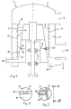
- a screening apparatus 1 of the invention comprising a generally cylindrical housing 2 with an inlet 3 for a fibre suspension to be separated, and a cylindrical screen 4 secured to the housing 2 and dividing the interior of the housing 2 into a central chamber 5 for receiving the fibre suspension from the inlet 3 at one end of the cylindrical screen 4 and an annular outer accept chamber 6 for receiving an accept fraction of the fibre suspension, which has passed through the screen 4.
- a rotor 7 provided with a number of circumferentially distributed peripheral wing elements 8 is journalled by bearings 9 on the housing 2 and positioned in the central chamber 5 coaxially with the cylindrical screen 4, so that the wing elements 8 sweep past the interior surface of the screen 4, when the rotor 7 is rotated by a drive motor (not shown).
- the housing 2 is provided with an accept outlet 10 for discharging the accept fraction from the accept chamber 6 and a reject outlet 11 for discharging the developed reject fraction from the interior of the screen 4 via a reject chamber 12 communicating with the central chamber 5.
- the rotor 7 has a truncated conical circumferential wall 13 and a radial wall 14 connected thereto at the base of the conical wall 13. At the connection between the walls 13 and 14, a part of the radial wall 14 is formed by a rotationally symmetrical wall element 15 of the rotor 7.
- an annular wall portion 19 extends radially inwardly from the conical wall 16 adjacent the wall element 15 of the rotor 7, so that a narrow annular passage 20 is defined between the wall element 15 and the wall portion 19.
- the wall element 15 of the rotor 7 is provided with at least one protrusion 21, which extends in the annular passage 20 but is spaced from the stationary wall portion 19.
- the annular passage 20 opens into the tubular screen 4 relatively close to the reject chamber 12. To achieve a satisfactory dilution of thickened reject fraction, the passage 20 should open into the screen 4 at a distance from the reject discharging end of the screen 4 which is about 5-50% of the axial length of the screen 4.
- the screening apparatus is provided with dilution liquid supply means comprising the above defined wall element 15, stationary circumferential wall 16, dilution liquid chamber 17 with its inlet 18, annular wall portion 19 and annular passage 20.
- the fibre suspension to be separated is supplied to the central chamber 5 through the inlet 3 and flows along the screen 4 while separating into an accept fraction, which passes through the screen 4 into the accept chamber 6 and discharges therefrom through the accept outlet 10, and a reject fraction, which flows from the screen 4 into the reject chamber 12 and discharges therefrom through the reject outlet 11.
- Dilution liquid usually water
- the dilution liquid flows past the annular wall portion 19 and through the annular passage 20 flushing the screen 4, so that detrimental thickening of the reject fraction is prevented.
- the annular passage 20 is kept clean by the rotation of the wall element 15 subjecting any particles present in the annular passage 20 to shearing actions.
- the protrusion 21 on the rotor 7 pushes away any particles present in the annular passage 20 during each revolution of the rotor 7.
Landscapes
- Chemical & Material Sciences (AREA)
- Chemical Kinetics & Catalysis (AREA)
- Engineering & Computer Science (AREA)
- Mechanical Engineering (AREA)
- Paper (AREA)
- Separation Of Solids By Using Liquids Or Pneumatic Power (AREA)
- Investigating Or Analysing Biological Materials (AREA)
- Automatic Analysis And Handling Materials Therefor (AREA)
Claims (8)
- Dispositif de tamisage (1) pour séparer des suspension de fibres, comprenant un boítier (2), une entrée (3) débouchant à l'intérieur du boítier pour une suspension de fibres devant être séparée, un tamis tubulaire fixe (4) divisant l'intérieur du boítier en une chambre centrale (5) servant à recevoir la suspension de fibres à partir de l'entrée, à une extrémité du tamis tubulaire, et une chambre extérieure d'acceptation (6) pour recevoir une fraction d'acceptation de la suspension de fibres, qui a traversée le tamis, un rotor (7) tourillonné sur le boítier et situé dans la chambre centrale coaxialement avec le tamis tubulaire, une chambre de rejet (12) pour recevoir une fraction de rejet développée à partir de l'autre extrémité du tamis, et des moyens (15 à 20) d'amenée d'un liquide de dilution pour amener un liquide de dilution à la chambre centrale, caractérisé en ce que les moyens d'amenée du liquide de dilution comprennent un élément à symétrie de révolution (15) du rotor et une partie de paroi annulaire fixe opposée (19), ledit élément et ladite partie de paroi définissant un passage annulaire (20) pour le liquide de dilution.
- Dispositif de tamisage selon la revendication 1, dans lequel le passage annulaire (20) débouche dans le tamis tubulaire (4).
- Dispositif de tamisage selon la revendication 2, dans lequel le passage annulaire (20) débouche dans le tamis (4) à une distance de ladite autre extrémité de tamis, qui est égale à environ 5 à 50 % de la longueur axiale du tamis.
- Dispositif de tamisage selon l'une quelconque des revendications 1 à 3, dans lequel le rotor (7) comprend une paroi circonférentielle (13) et une paroi radiale (14) raccordée à une extrémité de la paroi circonférentielle, l'élément à symétrie de révolution (15) faisant partie de ladite paroi radiale (14).
- Dispositif de tamisage selon la revendication 4, dans lequel les moyens d'amenée du liquide de dilution comprennent une paroi circonférentielle fixe (16) alignée avec la paroi circonférentielle (13) du rotor (7) et raccordée à la partie de paroi annulaire fixe (19), la paroi circonférentielle fixe (16) et la partie de paroi annulaire (19) définissant une chambre (17) pour le liquide de dilution en communication fluidique avec le passage annulaire (20).
- Dispositif de tamisage selon la revendication 5, dans lequel les parois circonférentielles (13, 16) du rotor (7) et de la chambre (17) d'alimentation en liquide se rétrécissent en direction de ladite une extrémité du tamis (4).
- Dispositif de tamisage selon l'une quelconque des revendications 1 à 6, dans lequel l'élément à symétrie de révolution (15) comporte au moins une partie saillante (21) qui s'étend dans le passage annulaire (20) mais est distante de la partie de paroi fixe (19).
- Dispositif de tamisage selon l'une quelconque des revendications 1 à 7, dans lequel la largeur axiale du passage annulaire (20) varie dans la direction circonférentielle.
Applications Claiming Priority (3)
| Application Number | Priority Date | Filing Date | Title |
|---|---|---|---|
| SE9701368A SE509134C2 (sv) | 1997-04-14 | 1997-04-14 | Silanordning med rejektutspädning |
| SE9701368 | 1997-04-14 | ||
| PCT/SE1998/000650 WO1998046821A1 (fr) | 1997-04-14 | 1998-04-08 | Appareil de tamisage dote d'un moyen d'alimentation en liquide de dilution |
Publications (2)
| Publication Number | Publication Date |
|---|---|
| EP1012378A1 EP1012378A1 (fr) | 2000-06-28 |
| EP1012378B1 true EP1012378B1 (fr) | 2002-12-11 |
Family
ID=20406551
Family Applications (1)
| Application Number | Title | Priority Date | Filing Date |
|---|---|---|---|
| EP98917868A Expired - Lifetime EP1012378B1 (fr) | 1997-04-14 | 1998-04-08 | Appareil de tamisage dote d'un moyen d'alimentation en liquide de dilution |
Country Status (8)
| Country | Link |
|---|---|
| US (1) | US6290067B1 (fr) |
| EP (1) | EP1012378B1 (fr) |
| JP (1) | JP4068665B2 (fr) |
| AT (1) | ATE229588T1 (fr) |
| AU (1) | AU7091798A (fr) |
| DE (1) | DE69810124T2 (fr) |
| SE (1) | SE509134C2 (fr) |
| WO (1) | WO1998046821A1 (fr) |
Families Citing this family (8)
| Publication number | Priority date | Publication date | Assignee | Title |
|---|---|---|---|---|
| SE512957C2 (sv) | 1999-03-29 | 2000-06-12 | Valmet Fibertech Ab | Silanordning med ett roterbart och ett stationärt silorgan |
| SE514071C2 (sv) | 1999-04-08 | 2000-12-18 | Valmet Fibertech Ab | Silanordning med axiellt förskjutbar spaltring |
| AT413391B (de) * | 2003-03-27 | 2006-02-15 | Andritz Ag Maschf | Sortierer zur reinigung einer fasersuspension |
| AT413390B (de) * | 2003-03-27 | 2006-02-15 | Andritz Ag Maschf | Sortierer zur reinigung einer fasersuspension |
| SE526033C3 (sv) * | 2003-11-06 | 2009-12-08 | Metso Paper Inc | Silanordning och silkorg för silning av massasuspensioner |
| SE534497C2 (sv) * | 2009-12-21 | 2011-09-13 | Metso Paper Inc | Silenhet, silanordning och metod för inspektion/justering av en axiell spalt |
| FI126520B (en) | 2016-03-16 | 2017-01-31 | Red Wire Oy | Method of screening and screening device |
| KR101771371B1 (ko) | 2016-12-26 | 2017-08-24 | 나성주 | 제지 원료 정선을 위한 스크린 머신, 스크린 머신용 케이싱 바디 및 스크린 바스켓 |
Family Cites Families (8)
| Publication number | Priority date | Publication date | Assignee | Title |
|---|---|---|---|---|
| GB1294980A (fr) * | 1970-05-11 | 1972-11-01 | ||
| US4267035A (en) * | 1979-08-27 | 1981-05-12 | The Black Clawson Company | Pressurized rotary screening apparatus |
| US4851111A (en) * | 1985-08-09 | 1989-07-25 | The Black Clawson Company | Apparatus for screening paper fiber stock |
| US4749474A (en) * | 1986-08-27 | 1988-06-07 | Ingersoll-Rand Company | Screening apparatus |
| US5096127A (en) * | 1990-08-22 | 1992-03-17 | Ingersoll-Rand Company | Apparatus for pressurized screening of a fibrous material liquid suspension |
| FI90792C (fi) * | 1992-05-19 | 1994-03-25 | Pom Dev Oy Ab | Menetelmä ja laite kuitususpension puhdistamiseksi |
| JP3065202B2 (ja) | 1993-10-20 | 2000-07-17 | 石川島播磨重工業株式会社 | 古紙パルプの選別方法および装置 |
| SE507905C2 (sv) * | 1995-10-11 | 1998-07-27 | Sunds Defibrator Ind Ab | Anordning för silning av massasuspensioner |
-
1997
- 1997-04-14 SE SE9701368A patent/SE509134C2/sv unknown
-
1998
- 1998-04-08 DE DE69810124T patent/DE69810124T2/de not_active Expired - Lifetime
- 1998-04-08 EP EP98917868A patent/EP1012378B1/fr not_active Expired - Lifetime
- 1998-04-08 AT AT98917868T patent/ATE229588T1/de active
- 1998-04-08 JP JP54380798A patent/JP4068665B2/ja not_active Expired - Fee Related
- 1998-04-08 US US09/402,916 patent/US6290067B1/en not_active Expired - Lifetime
- 1998-04-08 WO PCT/SE1998/000650 patent/WO1998046821A1/fr not_active Ceased
- 1998-04-08 AU AU70917/98A patent/AU7091798A/en not_active Abandoned
Also Published As
| Publication number | Publication date |
|---|---|
| DE69810124T2 (de) | 2003-07-17 |
| AU7091798A (en) | 1998-11-11 |
| DE69810124D1 (de) | 2003-01-23 |
| EP1012378A1 (fr) | 2000-06-28 |
| SE9701368L (sv) | 1998-10-15 |
| SE509134C2 (sv) | 1998-12-07 |
| JP4068665B2 (ja) | 2008-03-26 |
| WO1998046821A1 (fr) | 1998-10-22 |
| JP2001518995A (ja) | 2001-10-16 |
| SE9701368D0 (sv) | 1997-04-14 |
| ATE229588T1 (de) | 2002-12-15 |
| US6290067B1 (en) | 2001-09-18 |
Similar Documents
| Publication | Publication Date | Title |
|---|---|---|
| US4921400A (en) | Pump and a method of separating gas by such from a fluid to be pumped | |
| JP3822907B2 (ja) | パルプ懸濁液を処理する方法及び装置 | |
| CA2003088C (fr) | Trieuse | |
| EP1012378B1 (fr) | Appareil de tamisage dote d'un moyen d'alimentation en liquide de dilution | |
| CA1330207C (fr) | Poste de tamisage de rejets | |
| EP0017481A1 (fr) | Valve à fermeture automatique pour faciliter le débouchage d'un appareil de nettoyage centrifuge | |
| CA2012936C (fr) | Dispositif de tamisage pour les bouillies | |
| EP0498822B1 (fr) | Tamis sans chocs de pression | |
| US4880532A (en) | Sorting apparatus for fiber suspensions | |
| KR100710535B1 (ko) | 섬유질 현탁액을 세척하기 위한 여과기 | |
| WO1993023609A1 (fr) | Procede et appareil d'epuration de suspension de pate a papier | |
| US4919336A (en) | Shower pipes | |
| EP0975833B1 (fr) | Appareil de tamisage dote de moyens reducteurs de flux de rejet | |
| US4222863A (en) | Screening apparatus and method | |
| US4127479A (en) | Apparatus for straining suspensions | |
| US6131742A (en) | Device for separating contaminants from fibre pulp suspensions | |
| EP1125016B1 (fr) | Procede et appareil d'epaississement de suspensions de fibres | |
| US5034120A (en) | Method for keeping a screen or filter surface clear | |
| WO1998001206A1 (fr) | Appareil de filtration de liquides | |
| EP1159482B1 (fr) | Dispositif de tamisage | |
| GB2034609A (en) | Hydrocyclone separators | |
| CA2027564A1 (fr) | Depastilleur | |
| FI112256B (fi) | Menetelmä ja laite massan käsittelemiseksi | |
| JPH086079Y2 (ja) | 製紙用スクリーン | |
| SU1291638A1 (ru) | Фракционатор волокнистой суспензии |
Legal Events
| Date | Code | Title | Description |
|---|---|---|---|
| PUAI | Public reference made under article 153(3) epc to a published international application that has entered the european phase |
Free format text: ORIGINAL CODE: 0009012 |
|
| 17P | Request for examination filed |
Effective date: 19991014 |
|
| AK | Designated contracting states |
Kind code of ref document: A1 Designated state(s): AT BE CH DE DK ES FI FR GB GR IE IT LI LU MC NL PT SE |
|
| GRAG | Despatch of communication of intention to grant |
Free format text: ORIGINAL CODE: EPIDOS AGRA |
|
| 17Q | First examination report despatched |
Effective date: 20020308 |
|
| GRAG | Despatch of communication of intention to grant |
Free format text: ORIGINAL CODE: EPIDOS AGRA |
|
| GRAH | Despatch of communication of intention to grant a patent |
Free format text: ORIGINAL CODE: EPIDOS IGRA |
|
| GRAH | Despatch of communication of intention to grant a patent |
Free format text: ORIGINAL CODE: EPIDOS IGRA |
|
| GRAA | (expected) grant |
Free format text: ORIGINAL CODE: 0009210 |
|
| AK | Designated contracting states |
Kind code of ref document: B1 Designated state(s): AT BE CH DE DK ES FI FR GB GR IE IT LI LU MC NL PT SE |
|
| PG25 | Lapsed in a contracting state [announced via postgrant information from national office to epo] |
Ref country code: NL Free format text: LAPSE BECAUSE OF FAILURE TO SUBMIT A TRANSLATION OF THE DESCRIPTION OR TO PAY THE FEE WITHIN THE PRESCRIBED TIME-LIMIT Effective date: 20021211 Ref country code: LI Free format text: LAPSE BECAUSE OF FAILURE TO SUBMIT A TRANSLATION OF THE DESCRIPTION OR TO PAY THE FEE WITHIN THE PRESCRIBED TIME-LIMIT Effective date: 20021211 Ref country code: IT Free format text: LAPSE BECAUSE OF FAILURE TO SUBMIT A TRANSLATION OF THE DESCRIPTION OR TO PAY THE FEE WITHIN THE PRESCRIBED TIME-LIMIT;WARNING: LAPSES OF ITALIAN PATENTS WITH EFFECTIVE DATE BEFORE 2007 MAY HAVE OCCURRED AT ANY TIME BEFORE 2007. THE CORRECT EFFECTIVE DATE MAY BE DIFFERENT FROM THE ONE RECORDED. Effective date: 20021211 Ref country code: GR Free format text: LAPSE BECAUSE OF FAILURE TO SUBMIT A TRANSLATION OF THE DESCRIPTION OR TO PAY THE FEE WITHIN THE PRESCRIBED TIME-LIMIT Effective date: 20021211 Ref country code: CH Free format text: LAPSE BECAUSE OF FAILURE TO SUBMIT A TRANSLATION OF THE DESCRIPTION OR TO PAY THE FEE WITHIN THE PRESCRIBED TIME-LIMIT Effective date: 20021211 Ref country code: BE Free format text: LAPSE BECAUSE OF FAILURE TO SUBMIT A TRANSLATION OF THE DESCRIPTION OR TO PAY THE FEE WITHIN THE PRESCRIBED TIME-LIMIT Effective date: 20021211 |
|
| REF | Corresponds to: |
Ref document number: 229588 Country of ref document: AT Date of ref document: 20021215 Kind code of ref document: T |
|
| REG | Reference to a national code |
Ref country code: GB Ref legal event code: FG4D |
|
| RIN1 | Information on inventor provided before grant (corrected) |
Inventor name: WIKSTROEM, BJOERN Inventor name: SVENSSON, LENNART Inventor name: FORSLUND, KJELL Inventor name: BERGDAHL, ANDERS |
|
| REG | Reference to a national code |
Ref country code: CH Ref legal event code: EP |
|
| REG | Reference to a national code |
Ref country code: IE Ref legal event code: FG4D |
|
| REF | Corresponds to: |
Ref document number: 69810124 Country of ref document: DE Date of ref document: 20030123 |
|
| PG25 | Lapsed in a contracting state [announced via postgrant information from national office to epo] |
Ref country code: PT Free format text: LAPSE BECAUSE OF FAILURE TO SUBMIT A TRANSLATION OF THE DESCRIPTION OR TO PAY THE FEE WITHIN THE PRESCRIBED TIME-LIMIT Effective date: 20030311 Ref country code: DK Free format text: LAPSE BECAUSE OF FAILURE TO SUBMIT A TRANSLATION OF THE DESCRIPTION OR TO PAY THE FEE WITHIN THE PRESCRIBED TIME-LIMIT Effective date: 20030311 |
|
| REG | Reference to a national code |
Ref country code: SE Ref legal event code: TRGR |
|
| PG25 | Lapsed in a contracting state [announced via postgrant information from national office to epo] |
Ref country code: LU Free format text: LAPSE BECAUSE OF NON-PAYMENT OF DUE FEES Effective date: 20030408 Ref country code: IE Free format text: LAPSE BECAUSE OF NON-PAYMENT OF DUE FEES Effective date: 20030408 Ref country code: GB Free format text: LAPSE BECAUSE OF NON-PAYMENT OF DUE FEES Effective date: 20030408 |
|
| PG25 | Lapsed in a contracting state [announced via postgrant information from national office to epo] |
Ref country code: MC Free format text: LAPSE BECAUSE OF NON-PAYMENT OF DUE FEES Effective date: 20030430 |
|
| NLV1 | Nl: lapsed or annulled due to failure to fulfill the requirements of art. 29p and 29m of the patents act | ||
| PG25 | Lapsed in a contracting state [announced via postgrant information from national office to epo] |
Ref country code: ES Free format text: LAPSE BECAUSE OF FAILURE TO SUBMIT A TRANSLATION OF THE DESCRIPTION OR TO PAY THE FEE WITHIN THE PRESCRIBED TIME-LIMIT Effective date: 20030627 |
|
| REG | Reference to a national code |
Ref country code: CH Ref legal event code: PL |
|
| ET | Fr: translation filed | ||
| PLBE | No opposition filed within time limit |
Free format text: ORIGINAL CODE: 0009261 |
|
| STAA | Information on the status of an ep patent application or granted ep patent |
Free format text: STATUS: NO OPPOSITION FILED WITHIN TIME LIMIT |
|
| GBPC | Gb: european patent ceased through non-payment of renewal fee |
Effective date: 20030408 |
|
| 26N | No opposition filed |
Effective date: 20030912 |
|
| REG | Reference to a national code |
Ref country code: IE Ref legal event code: MM4A |
|
| PGFP | Annual fee paid to national office [announced via postgrant information from national office to epo] |
Ref country code: FR Payment date: 20140430 Year of fee payment: 17 |
|
| REG | Reference to a national code |
Ref country code: FR Ref legal event code: ST Effective date: 20151231 |
|
| PG25 | Lapsed in a contracting state [announced via postgrant information from national office to epo] |
Ref country code: FR Free format text: LAPSE BECAUSE OF NON-PAYMENT OF DUE FEES Effective date: 20150430 |
|
| PGFP | Annual fee paid to national office [announced via postgrant information from national office to epo] |
Ref country code: DE Payment date: 20170412 Year of fee payment: 20 |
|
| PGFP | Annual fee paid to national office [announced via postgrant information from national office to epo] |
Ref country code: SE Payment date: 20170421 Year of fee payment: 20 Ref country code: AT Payment date: 20170421 Year of fee payment: 20 Ref country code: FI Payment date: 20170419 Year of fee payment: 20 |
|
| REG | Reference to a national code |
Ref country code: DE Ref legal event code: R071 Ref document number: 69810124 Country of ref document: DE |
|
| REG | Reference to a national code |
Ref country code: AT Ref legal event code: MK07 Ref document number: 229588 Country of ref document: AT Kind code of ref document: T Effective date: 20180408 |
|
| REG | Reference to a national code |
Ref country code: SE Ref legal event code: EUG |