EP1012582B1 - Procede et dispositif servant a detecter des irregularites dans un produit - Google Patents
Procede et dispositif servant a detecter des irregularites dans un produit Download PDFInfo
- Publication number
- EP1012582B1 EP1012582B1 EP98913454A EP98913454A EP1012582B1 EP 1012582 B1 EP1012582 B1 EP 1012582B1 EP 98913454 A EP98913454 A EP 98913454A EP 98913454 A EP98913454 A EP 98913454A EP 1012582 B1 EP1012582 B1 EP 1012582B1
- Authority
- EP
- European Patent Office
- Prior art keywords
- light
- product
- scattered
- detector
- band
- Prior art date
- Legal status (The legal status is an assumption and is not a legal conclusion. Google has not performed a legal analysis and makes no representation as to the accuracy of the status listed.)
- Expired - Lifetime
Links
- 238000000034 method Methods 0.000 title claims abstract description 13
- 238000001514 detection method Methods 0.000 claims abstract description 25
- 239000007787 solid Substances 0.000 claims description 4
- 238000004088 simulation Methods 0.000 description 8
- 240000004713 Pisum sativum Species 0.000 description 6
- 235000010582 Pisum sativum Nutrition 0.000 description 6
- 230000001419 dependent effect Effects 0.000 description 4
- 230000035945 sensitivity Effects 0.000 description 3
- 240000006365 Vitis vinifera Species 0.000 description 2
- 235000014787 Vitis vinifera Nutrition 0.000 description 2
- 241000143060 Americamysis bahia Species 0.000 description 1
- 229910000831 Steel Inorganic materials 0.000 description 1
- 239000002775 capsule Substances 0.000 description 1
- 239000000109 continuous material Substances 0.000 description 1
- 238000012937 correction Methods 0.000 description 1
- 238000006073 displacement reaction Methods 0.000 description 1
- 239000003814 drug Substances 0.000 description 1
- 229940079593 drug Drugs 0.000 description 1
- 230000005670 electromagnetic radiation Effects 0.000 description 1
- 235000013305 food Nutrition 0.000 description 1
- 235000012020 french fries Nutrition 0.000 description 1
- 238000005259 measurement Methods 0.000 description 1
- 238000012986 modification Methods 0.000 description 1
- 230000004048 modification Effects 0.000 description 1
- 238000012544 monitoring process Methods 0.000 description 1
- 230000000149 penetrating effect Effects 0.000 description 1
- 239000002985 plastic film Substances 0.000 description 1
- 229920006255 plastic film Polymers 0.000 description 1
- 230000000750 progressive effect Effects 0.000 description 1
- 239000010959 steel Substances 0.000 description 1
- 239000004753 textile Substances 0.000 description 1
Images


Classifications
-
- G—PHYSICS
- G01—MEASURING; TESTING
- G01N—INVESTIGATING OR ANALYSING MATERIALS BY DETERMINING THEIR CHEMICAL OR PHYSICAL PROPERTIES
- G01N21/00—Investigating or analysing materials by the use of optical means, i.e. using sub-millimetre waves, infrared, visible or ultraviolet light
- G01N21/84—Systems specially adapted for particular applications
- G01N21/88—Investigating the presence of flaws or contamination
- G01N21/89—Investigating the presence of flaws or contamination in moving material, e.g. running paper or textiles
- G01N21/8901—Optical details; Scanning details
Definitions
- the invention concerns a method for detecting irregularities in a product, in which at least one light band, more specifically consisting of one or more laser beams, is directed towards this product by means of a moving mirror, whereby the product moves in a particular direction through a detection zone, so that said light band, which preferably moves transversely across the path of the product, is at least partially scattered and/or reflected by said product, whereby the scattered light is reflected via said mirror and at least partially detected by at least one detector, the light stream of the scattered light then being compared with the light stream of the scattered light from a good part of the product that shows no irregularities, in order to detect irregularities in the product.
- at least one light band more specifically consisting of one or more laser beams
- scattered light is meant in this description on the one hand-the light which is diffusely reflected at the surface of a product, and on the other hand the light that is emitted by the product as a result of said light band at least partly penetrating it, spreading into it, and thereby making the corresponding part of the product light up.
- the light stream of scattered light which is thus detected by at least one detector, is dependent on the position of said band.
- the value of the signal generated by means of the detector which determines whether a part of the product must be characterised as a good part or as a foreign component or a part of lower-value, is dependent on the position of the light band.
- the signal coming from said detector is electronically modified, for example by multiplying it by a factor which is dependent on the position of the light band, so that a signal is obtained which does not depend on the position of the light band.
- the aim of the invention is to deal with this by proposing a method which does not have these disadvantages, and which ensures that irregularities in a product are detected with uniform sensitivity, and which makes it possible to carry out very good detection or classification, both qualitative and quantitative, in a very economical manner.
- the invention also concerns a device according to claim 3.
- Said diaphragm can advantageously be provided with small, movable plates at the edge of said opening, where said plates enable the size and/or shape of the opening to be adjusted, in such a manner that the light stream falling on said detector is independent of the position of said light band.
- the invention further concerns a sorting apparatus for separating foreign components or lower-value parts from good parts of a product which consists of parts that are loose from each other, where said sorting apparatus is provided with said device according to claim 3.
- the sorting apparatus makes it possible for lower-value peas such as overripe peas, and foreign objects such as small stones, stalks and suchlike, to be separated from peas that are suitable for human consumption.
- the invention concerns among other things sorting apparatuses for products consisting of loose parts of a very different nature, such as peas, raisins, shrimps, dried or deep-frozen foods, all types of ore, drugs in tablet or capsule form, etc.
- Fig. 1 shows a classic embodiment of a device which can be mounted in a sorting apparatus.
- This sorting apparatus is mainly used for separating lower-value parts and foreign objects from the good parts of a product.
- a product consisting of loose parts is moved in a wide stream through the detection zone of said device, in order to enable the loose parts of the product to be characterised, and thus to distinguish between the good parts, which have essentially no irregularities, and the lower-value parts or foreign objects.
- the device is provided with two light sources 1' and 1" which each generate an intense, focused band of light, respectively 2' and 2". Both light sources 1 and 1" generate light of different frequency and are brought together into a band 2 of laser beams by a selectively semi-reflecting mirror 3' (dichroic mirror) and an ordinary mirror 3".
- This light band 2 is reflected towards a moving, prismatic mirror 4.
- the faces 5 of this mirror 4 are reflective and are set at essentially the same angle to one another. Furthermore, this prismatic mirror 4 rotates around its central axis 6 at an essentially constant speed. The light band 2 falling on such a face 5 is directed towards the product to be sorted.
- the light band 2 falling on the faces 5 moves transversely across the stream of parts 7 of the product.
- said band 2 moves each time in the same direction between two positions 14 and 15 over the width of the stream of parts 7, as shown by the arrow 2'''.
- the frequency of this movement depends among other things on the speed of rotation of the mirror 4, and consists preferably of between 500 and 8,000 movements per second.
- Said detection zone extends between the two positions 14 and 15 of the light band 2, where still a measurement of the scattered light is carried out.
- the light band 2 When the light band 2, via one of the faces 5, falls on a part 7 of the product, it is scattered and/or reflected by said part 7. As shown by arrows 8, scattered light is at least partly captured by the same face 5, and, via said face 5, is led along approximately the same path as the light band 2 to a beam splitter 9 which reflects the scattered light 8''' at an angle via a lens system 10 to a so-called beam splitter 11.
- the beam splitter 9 has for example a central opening which enables the light band 2 from the light sources 1' and 1" to pass through unimpeded.
- scattered light may be reflected back to said detector via a face 5 of the mirror 4 that is different from the face 5 on which the light band falls.
- the beam splitter 11 separates the light 8''' scattered by the product and originating from the respective light sources 1 and 1" into two light bands 8' and 8" of different frequency. Band 8' then falls on a detector 13, while band 8 falls on a detector 12 via a mirror 9'.
- the device is provided with a background in the form of a tube 16 extending perpendicularly to the direction of displacement of said product, in such a manner that the light band 2 falls on it, where the parts 7 of the product move over said tube 16 between the latter and said mirror 4.
- This tube 16 preferably has the same characteristics as a good part 7 as regards the scattering of the light band 2.
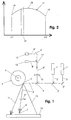
- a signal 17 is generated by the detectors 12 and 13 on which at least a part 8''' of the light scattered by said tube falls, as shown in fig. 2.
- This signal is a measure of the scattered light.
- the Y axis shows the magnitude of this signal as a function of the position of the light band 2, shown on the X axis.
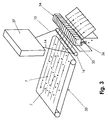
- Fig. 3 shows a traditional sorting apparatus for products consisting of parts 7 that are loose from one another, for example granular products, provided with a conveyor belt 33, a compressed air device 34 forming a removal system, and the device 37 as described above with said tube 16.
- the conveyor belt 33 With the help of the conveyor belt 33, the parts 7 are moved through the detection zone over this tube 16.
- the conveyor belt 33 extends to the tube 16 in such a manner that the parts 7, which are moved by the conveyor belt 33 in the direction of the detection zone and the tube 16, are travelling at a sufficiently high velocity when leaving the conveyor belt 33 to move successively through the detection zone, over the tube 16 and past the compressed air device 34.
- these parts 7 are recognised by the device 37 described above as being lower-value parts or foreign objects or as being good parts,.
- said compressed air device 34 is activated.
- a valve 35 of said compressed air device 34 is opened, where said valve is in a position corresponding to said foreign object or lower-value part. In this way a powerful, directed current of air 36 is created which removes the foreign object or lower-value part from the product.
- the signal generated by said detector 12 or 13, represented by the curve 17 in fig. 2 has a maximum 18 for the position where the band 2 falls on said side 5 at an angle of substantially 45°, and a considerably weaker signal 19 is obtained when the band 2 is in one of the extreme positions 14 or 15.
- a weaker signal is obtained whenever the length of the band 2 between the prismatic mirror 4 and the tube 16 is essentially at its smallest. Accordingly, a signal is obtained as represented by the convex curve 17, as a function of the position of the light band 2.
- the signal thus generated is divided into a number of small intervals 17', where the signal of a particular interval 17' is amplified to a certain value so that a final signal is obtained that is independent of the position of the light band 2 when the latter falls on the tube 16. Modifying this signal is done by means of suitable electronics, for example by multiplying the signal for a particular interval 17' by a suitable factor.
- the signals 17 generated by the detector 12 or 13 lie above or below predetermined thresholds, and said lower-value part or foreign object is then ejected from the product stream.
- the latter signal In order to be able to compare the signal from such a lower-value part or foreign object with said thresholds and with the signal for a good part, the latter signal must also be amplified for the corresponding interval 17'.
- the device in fig. 1 it is preferable for the device in fig. 1, however, to compare the value for a predetermined ratio of the signal values generated by each of the two detectors 12 and 13 with the ratio for a good part in order to determine whether a part 7 of the product shows an irregularity, and therefore whether it is a foreign object or lower-value part.
- the signal generated by a detector 12 or 13 is compared with a reference signal that has a similar shape to the curved signal 17 as shown in fig. 2.
- comparing a ratio or combination of the signals from different detectors 12 and 13 with particular thresholds is a highly complex operation because of the curved shape of the signal 17 for each of the detectors 12 and 13.
- the curved shape of the signal 17 is due to among other things the variation in the angle at which said light band falls on the tube 16, as a result of which the scattered light will have a maximum intensity in a correspondingly varying direction.
- the percentage reflection which is dependent on the angle of incidence of the band 8''' of scattered light on a face 5, varies according to the position of the light band 2 and contributes to the curved shape of the aforesaid signal.
- the area of the beam splitter 9 illuminated by the scattered light 8''' is not always the same, as is shown in figs. 4, 5 and 6.
- the solid angle of the band of scattered light 8''' falling on the face 5 also varies according to the position of said face 5, and thus of the light band 2. This solid angle falling on a face 5 is at its greatest when the distance between the point at which the band 2 falls on the mirror and the corresponding point at which it falls on the tube 16 is at its smallest.
- Figs. 4, 5 and 6 schematically show the cross section of the band of scattered light 8''' in a different position each time, represented by a shaded rectangle 30, 31, 32 and 30', 31' and 32', as observed by the aforesaid detectors.
- the passage of the scattered light 8''' to said detector 12 or 13 is adjusted according to the position of the light band 2, so that the scattered light always comes from a solid angle of essentially the same size. This ensures that the light stream 8''' of the light 8 scattered by part 7 and falling on the detector 12 or 13 is independent of the position of said part 7 in said detection zone, or in other words independent of the position of said light band 2. In this way, a substantially uniform sensitivity is obtained when qualifying the parts 7 of the product to be sorted.
- the device according to the invention is provided with an adjustable aperture element 20, more specifically a diaphragm 23, as shown in fig. 7.
- This diaphragm 23 has an opening 22 with a progressive narrowing in the direction of the point on which, globally seen, the greatest stream of scattered light 8''' falls.
- This narrowing 24 is arranged in a direction perpendicular to the plane in which said light band 2 moves.
- the form and the size of the opening 22 in the diaphragm 23 are therefore chosen so that whenever said light band 2 is directed towards the product, the signal generated by the detector 12 or 13 on which said scattered light 8''' falls is substantially independent of the position of said light band 2.
- the diaphragm can be asymmetrical, so that, for example, the split formed by said opening 22 has a different width at either end.
- said narrowing 24 does not necessarily have to be in the middle part of said opening 22.
- said diaphragm 23 has means to adjust the size and the shape of said opening 22 to suit the specific requirements or characteristics of the device or of the sorting apparatus.
- Such a diaphragm 23 is shown in fig. 8.
- This diaphragm 23 is provided with a rectangular opening 26, with small, movable plates 25 on either side of said opening 26. These plates 25 are rectangular and extend in their longitudinal direction perpendicular to the edge of said opening 26. By moving said plates 25 in relation to one another and to the opening 26, the opening 22 of said diaphragm 23 can be adjusted.
- the ends of the plates 25 facing said opening 22 are oblique to a certain extent, so that after the adjustment of said opening 22, the latter has an approximately continuous edge.
- simulation parts 27 are placed in the detection zone, as is shown in fig. 10. These simulation parts 27 are formed by little bars which preferably have a cross-section that is essentially the same as that of the parts 7 of the product to be sorted. The simulation parts 27 are placed with the longitudinal axis perpendicular to the plane formed by the moving band 2. The light stream of the scattered light from these simulation parts that falls on said detector 12 or 13 is then adjusted until a constant signal 17 is obtained, by adjusting the opening 22 of the diaphragm 23 with the help of the movable plates 25.
- the opening 22 of the diaphragm 23 will first be adjusted to a position where the detector 12 or 13 has the lowest value.
- Fig. 9 shows a graph of the signal generated by the detector 12 or 13 when the light band 2 is moved across said simulation parts 27 and when said tube 16 scatters essentially no light from the light band 2.
- This graph shows the different peaks 28 corresponding to the signal generated by the detector 12 or 13 for the corresponding simulation parts 27.
- these peaks 28 are reduced to a constant value, as shown by line 29.
- the diaphragm 23 will show an opening 22 with a shape as shown schematically in fig. 10.
- an object that scatters said light band 2, such as a part 7 of the product is brought into various positions in said detection zone or moved through said detection zone, with the opening 22 of the diaphragm 23 being adjusted so that the signal generated by the detector 12 and 13 has the same value for every position of that object.
- said adjusting element 20, more specifically a diaphragm 23, can be mounted between said detection zone and the polygonal mirror 4, as shown in fig. 10.
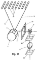
- Fig. 11 shows some other possible positions for this adjusting element 20, namely between the mirror 4 and the beam splitter 9, or between said beam splitter 9 and a lens system 10, or in front of the detector 13.
- This adjusting element 20 can in principle be positioned at all places where the light stream 8''' falling on the detector 12 or 13 moves in accordance with the position of the light band 2.
- rotating mirror 4 it is also possible for the rotating mirror 4 to be replaced by another moving mirror, such as a rapidly vibrating mirror.
- the sorting apparatus can, if required, also work with several light bands, said light bands being preferably laser beams or bands.
- the number of detectors need not necessarily be related to the number of light bands. For example, one frequency of scattered light may be detected by several detectors.
- light in this description is meant all electromagnetic radiation, preferably with a wavelength of between 100 nm and 10,000 nm. In most cases, however, light with a wavelength of between 400 and 1,200 nm will be used.
- the aforesaid device has no tube 16.
- the device according to the invention can be used for monitoring the quality of and/or irregularities in a product or parts of a product.
- the product can consist of a continuous material such as a steel plate, a plastic film, a strip of paper or a woven textile, with the device being moved relative to the surface of the product in order to detect irregularities in it.
Landscapes
- General Health & Medical Sciences (AREA)
- General Physics & Mathematics (AREA)
- Physics & Mathematics (AREA)
- Health & Medical Sciences (AREA)
- Life Sciences & Earth Sciences (AREA)
- Chemical & Material Sciences (AREA)
- Textile Engineering (AREA)
- Analytical Chemistry (AREA)
- Engineering & Computer Science (AREA)
- Biochemistry (AREA)
- Immunology (AREA)
- Pathology (AREA)
- Sorting Of Articles (AREA)
- Length Measuring Devices With Unspecified Measuring Means (AREA)
- Length Measuring Devices By Optical Means (AREA)
- Measuring Arrangements Characterized By The Use Of Fluids (AREA)
Claims (11)
- Procédé servant à détecter des irrégularités dans un produit, dans lequel au moins une bande de lumière (2) consistant en au moins un faisceau laser ou un faisceau lumineux, est orienté en direction dudit produit (7) au moyen d'un miroir mobile (4, 5), dans lequel le produit (7) se déplace dans une direction particulière à travers une zone de détection, d'une manière telle que ladite bande (2) qui se déplace transversalement à travers la direction de déplacement du produit (7), soit au moins partiellement dispersée et/ou réfléchie par ledit produit (7), dans lequel la lumière dispersée est réfléchie via ledit miroir (4, 5) et est séparée de la lumière réfléchie, la lumière dispersée étant au moins en partie capturée par au moins un détecteur (12, 13) en vue de détecter des irrégularités dans le produit, caractérisé en ce que la quantité de lumière dispersée par un article du produit et capturée par ledit détecteur (12, 13) est déterminée en fonction de la position de ladite bande de lumière (2) transversalement à travers la direction de déplacement du produit au moyen d'un élément d'ouverture réglable (20) comportant une ouverture (22) qui est ajustée de manière à se rétrécir progressivement en direction du point de ladite ouverture sur laquelle le plus grand flux de lumière dispersée (8''') tombe, de telle sorte que la quantité de lumière capturée par ledit détecteur soit indépendante de la position à travers le produit dudit article dans ladite zone de détection, ou en d'autres termes, soit indépendante de la position de ladite bande de lumière (2) à travers le produit.
- Procédé selon la revendication 1, caractérisé en ce que la quantité de lumière dispersée (8''') par un article du produit et capturée par ledit détecteur (12, 13) est déterminée en fonction de la position de ladite bande de lumière (2) au moyen dudit élément d'ouverture réglable (20), de telle sorte que la lumière dispersée (8''') provienne toujours d'un angle solide de la même taille.
- Dispositif servant à détecter des irrégularités dans un produit qui se déplace dans une direction particulière à travers une zone de détection, comprenant au moins un détecteur (12, 13) et un moyen pour générer au moins une bande de lumière (2) orientée en direction dudit produit (7) au moyen d'un miroir mobile (4, 5) d'une manière telle que la lumière en provenance de ladite bande de lumière (2) soit dispersée et/ou réfléchie par un article dudit produit (7), dans lequel la lumière (8) dispersée par ledit produit (7) est réfléchie via ledit miroir (4, 5) et est séparée de la lumière réfléchie, la lumière dispersée étant au moins en partie capturée par ledit détecteur (12, 13), caractérisé en ce que, entre ledit détecteur (12, 13) et la zone de détection à travers laquelle ledit produit (7) doit se déplacer, un élément d'ouverture réglable (20) comprenant un diaphragme réglable (23) est prévu, et comporte une ouverture qui se rétrécit progressivement en direction du point sur ladite ouverture sur lequel le plus grand flux de lumière dispersée (8''') tombe, de manière à laisser passer uniquement une partie de la lumière (8) dispersée par un article particulier du produit (7), d'une manière telle que la quantité de lumière dispersée qui tombe sur ledit détecteur (13, 13) soit indépendante de la position, transversalement à travers la direction de déplacement du produit, dudit article (7) dans la zone de détection.
- Dispositif selon la revendication 3, caractérisé en ce que ledit diaphragme (23) comprend de petites plaques mobiles (25) au bord de ladite ouverture (22, 26) qui permettent de régler la taille et/ou la forme de l'ouverture (22) de telle sorte que le flux de lumière (8''') qui tombe sur ledit détecteur (12, 13) soit indépendant de la position de ladite bande de lumière (2) à travers le produit.
- Dispositif selon l'une des revendications 3 ou 4, caractérisé en ce que ladite ouverture (22) présente un rétrécissement (24) dans une direction perpendiculaire au plan auquel ladite bande de lumière (2) se déplace parallèlement.
- Dispositif selon l'une des revendications 3 à 5, caractérisé en ce que ledit miroir mobile (4) est en forme de prisme et est pourvu d'un moyen qui lui permet de tourner autour de son axe central (6), où les faces (5) dudit miroir (4) sont réfléchissantes et sont de préférence réglées au même angle l'une par rapport à l'autre.
- Dispositif selon l'une quelconque des revendications 3 à 6, caractérisé en ce qu'au moins une partie de la lumière (8) dispersée par lesdits articles (7) passe à travers le dispositif d'ouverture réglable (20) et est réfléchie via ledit miroir (4) vers un dispositif de fractionnement de faisceau (9) qui fait en sorte que la lumière dispersée (8''') tombe au moins en partie sur ledit détecteur (12, 13), et sépare celle-ci de ladite bande de lumière (2) ainsi que de toute bande de lumière réfléchie par lesdits produits (7).
- Dispositif selon l'une quelconque des revendications 3 à 7, caractérisé en ce que ledit élément d'ouverture réglable (20) est monté entre ladite zone de détection et ledit miroir mobile (4).
- Dispositif selon la revendication 7, caractérisé en ce que l'élément d'ouverture réglable (20) est monté entre ledit miroir mobile (4) et ledit dispositif de fractionnement de faisceau (9).
- Dispositif selon la revendication 7, caractérisé en ce que ledit élément de réglage (20) est monté entre ledit dispositif de fractionnement de faisceau (9) et ledit détecteur (12, 13).
- Appareil de tri servant à détecter et/ou à séparer des corps étrangers ou des articles de mauvaise qualité parmi des articles de bonne quantité dans un produit constitué d'articles séparés les uns des autres, caractérisé en ce qu'il est équipé du dispositif selon l'une des revendications 3 à 10.
Applications Claiming Priority (3)
| Application Number | Priority Date | Filing Date | Title |
|---|---|---|---|
| BE9700293 | 1997-03-28 | ||
| BE9700293A BE1011076A3 (nl) | 1997-03-28 | 1997-03-28 | Werkwijze en inrichting voor het detecteren van onregelmatigheden in een produkt. |
| PCT/BE1998/000042 WO1998044335A1 (fr) | 1997-03-28 | 1998-03-25 | Procede et dispositif servant a detecter des irregularites dans un produit |
Publications (2)
| Publication Number | Publication Date |
|---|---|
| EP1012582A1 EP1012582A1 (fr) | 2000-06-28 |
| EP1012582B1 true EP1012582B1 (fr) | 2004-08-04 |
Family
ID=3890436
Family Applications (1)
| Application Number | Title | Priority Date | Filing Date |
|---|---|---|---|
| EP98913454A Expired - Lifetime EP1012582B1 (fr) | 1997-03-28 | 1998-03-25 | Procede et dispositif servant a detecter des irregularites dans un produit |
Country Status (8)
| Country | Link |
|---|---|
| US (1) | US6473168B1 (fr) |
| EP (1) | EP1012582B1 (fr) |
| AT (1) | ATE272835T1 (fr) |
| AU (1) | AU6815098A (fr) |
| BE (1) | BE1011076A3 (fr) |
| DE (1) | DE69825456T2 (fr) |
| ES (1) | ES2226116T3 (fr) |
| WO (1) | WO1998044335A1 (fr) |
Families Citing this family (16)
| Publication number | Priority date | Publication date | Assignee | Title |
|---|---|---|---|---|
| DE19816881B4 (de) * | 1998-04-17 | 2012-01-05 | Gunther Krieg | Verfahren und Vorrichtung zur Detektion und Unterscheidung zwischen Kontaminationen und Gutstoffen sowie zwischen verschiedenen Farben in Feststoffpartikeln |
| WO2000057160A2 (fr) * | 1999-03-19 | 2000-09-28 | Tiedemanns-Joh. H. Andresen Ans, Trading As Tite Ch Autosort | Inspection de matiere |
| JP3587745B2 (ja) | 1999-09-08 | 2004-11-10 | 株式会社ニチレイ | 甲殻類の剥ぎ残し殻の検出排除方法及び装置 |
| US6864970B1 (en) | 2000-10-11 | 2005-03-08 | Best N.V. | Apparatus and method for scanning products with a light beam to detect and remove impurities or irregularities in a conveyed stream of the products |
| EP1498723A1 (fr) * | 2003-07-17 | 2005-01-19 | Hauni Maschinbau AG | Méthode pour reconnaítre des corps étrangers dans une ligne continue de produits et appareil pour la mise en oevre de ce méthode |
| JP2005037398A (ja) * | 2003-07-17 | 2005-02-10 | Hauni Maschinenbau Ag | 連続して送られる製品の内部の異物を認識する方法及びこの方法を実施する装置 |
| BE1017422A3 (nl) | 2006-12-08 | 2008-09-02 | Visys Nv | Werkwijze en inrichting voor het inspecteren en sorteren van een productstroom. |
| EP1975603A1 (fr) * | 2007-03-27 | 2008-10-01 | Visys NV | Procédé et système à utiliser pour inspecter et/ou retirer des objets non appropriés d'un flux de produits et appareil de tri mettant en oeuvre celui-ci |
| NO336546B1 (no) * | 2010-09-24 | 2015-09-21 | Tomra Sorting As | Apparat og fremgangsmåte for inspeksjon av materie |
| US8812149B2 (en) | 2011-02-24 | 2014-08-19 | Mss, Inc. | Sequential scanning of multiple wavelengths |
| NO336441B1 (no) * | 2012-01-24 | 2015-08-17 | Tomra Sorting As | Anordning, system og fremgangsmåte for optisk detektering av materie |
| PL2671651T3 (pl) | 2012-06-07 | 2015-10-30 | Visys Nv | Urządzenie i sposób dla kontrolowania i sortowania strumienia produktów |
| PL2918967T3 (pl) * | 2012-11-07 | 2018-10-31 | Artec Europe S.A.R.L. | Sposób monitorowania wymiarów liniowych obiektów trójwymiarowych |
| WO2015063300A1 (fr) | 2013-11-04 | 2015-05-07 | Tomra Sorting Nv | Appareil d'inspection |
| US10345789B2 (en) | 2016-06-21 | 2019-07-09 | Scientific Games International, Inc. | System and method for variable perforation profiles in a stack of lottery tickets |
| WO2018077866A1 (fr) | 2016-10-24 | 2018-05-03 | Tomra Sorting Nv | Procédé et système de détection d'une signature diamant |
Family Cites Families (8)
| Publication number | Priority date | Publication date | Assignee | Title |
|---|---|---|---|---|
| US2672799A (en) * | 1946-10-18 | 1954-03-23 | Terwilliger Ivan Melville | Light gate iris |
| DE2011470B2 (de) * | 1970-03-11 | 1971-12-23 | Siemens AG, 1000 Berlin und 8000 München, Zeiss, Carl, 7920 Heidenheim | Verfahren zum auswerten eines nach einem rasterverfahren auf genommenen bildes |
| GB1521527A (en) * | 1975-10-31 | 1978-08-16 | Xerox Corp | Electrostatographic reproduction methods and machines |
| JPS55129733A (en) * | 1980-03-10 | 1980-10-07 | Matsushita Electric Works Ltd | Color deficiency detection unit for sheet material |
| GB2219394B (en) * | 1988-05-06 | 1992-09-16 | Gersan Ets | Sensing a narrow frequency band of radiation and examining objects or zones |
| JP3048168B2 (ja) * | 1990-07-19 | 2000-06-05 | キヤノン株式会社 | 表面状態検査装置及びこれを備える露光装置 |
| JP2651815B2 (ja) * | 1991-07-30 | 1997-09-10 | 株式会社堀場製作所 | 異物検査装置 |
| JPH0543116U (ja) * | 1991-11-08 | 1993-06-11 | 旭光学工業株式会社 | 光学装置における光検出センサの配設構造 |
-
1997
- 1997-03-28 BE BE9700293A patent/BE1011076A3/nl active
-
1998
- 1998-03-25 EP EP98913454A patent/EP1012582B1/fr not_active Expired - Lifetime
- 1998-03-25 WO PCT/BE1998/000042 patent/WO1998044335A1/fr not_active Ceased
- 1998-03-25 US US09/402,055 patent/US6473168B1/en not_active Expired - Lifetime
- 1998-03-25 ES ES98913454T patent/ES2226116T3/es not_active Expired - Lifetime
- 1998-03-25 AU AU68150/98A patent/AU6815098A/en not_active Abandoned
- 1998-03-25 AT AT98913454T patent/ATE272835T1/de not_active IP Right Cessation
- 1998-03-25 DE DE69825456T patent/DE69825456T2/de not_active Expired - Lifetime
Also Published As
| Publication number | Publication date |
|---|---|
| AU6815098A (en) | 1998-10-22 |
| DE69825456T2 (de) | 2005-08-04 |
| DE69825456D1 (de) | 2004-09-09 |
| ES2226116T3 (es) | 2005-03-16 |
| WO1998044335A1 (fr) | 1998-10-08 |
| ATE272835T1 (de) | 2004-08-15 |
| BE1011076A3 (nl) | 1999-04-06 |
| EP1012582A1 (fr) | 2000-06-28 |
| US6473168B1 (en) | 2002-10-29 |
Similar Documents
| Publication | Publication Date | Title |
|---|---|---|
| EP1012582B1 (fr) | Procede et dispositif servant a detecter des irregularites dans un produit | |
| EP1332353B1 (fr) | Appareil et procede permettant de balayer des produits a l'aide d'un faisceau lumineux afin de detecter et de supprimer des impuretes ou des irregularites dans un flux de produits transporte | |
| AU646542B2 (en) | Monitoring an apparatus which uses scanned radiation | |
| US9006599B2 (en) | Method and device for sorting products | |
| US6059117A (en) | Method for sorting product | |
| CA2104470C (fr) | Classement ou tri | |
| CA2310838A1 (fr) | Procede et dispositif pour l'identification et le tri d'objets transportes sur bande | |
| EP0838274A2 (fr) | Systèmes optiques pour dispositif de tri | |
| BE1026632B1 (nl) | Sorteerapparaat | |
| IES66928B2 (en) | Optical inspection system | |
| RU2346759C2 (ru) | Сортирующее устройство и способы сортировки | |
| EP2186576B1 (fr) | Procédé et dispositif de tri de produits | |
| EP4556889A1 (fr) | Détection de émerillons | |
| AU605209B2 (en) | Improvements in material sorting | |
| AU2004100065A4 (en) | Optical Ore Sorter | |
| SU1036383A1 (ru) | Способ фотометрической сепарации кусковых материалов | |
| JPH0618408A (ja) | 拡散反射光計測用光学系及び反射分光計測装置 | |
| AU2004266181B2 (en) | Sorting apparatus and methods | |
| GB2116705A (en) | Handling of mechanical components |
Legal Events
| Date | Code | Title | Description |
|---|---|---|---|
| PUAI | Public reference made under article 153(3) epc to a published international application that has entered the european phase |
Free format text: ORIGINAL CODE: 0009012 |
|
| 17P | Request for examination filed |
Effective date: 19991102 |
|
| AK | Designated contracting states |
Kind code of ref document: A1 Designated state(s): AT BE CH DE DK ES FI FR GB GR IE IT LI LU MC NL PT SE |
|
| 17Q | First examination report despatched |
Effective date: 20011129 |
|
| GRAP | Despatch of communication of intention to grant a patent |
Free format text: ORIGINAL CODE: EPIDOSNIGR1 |
|
| GRAS | Grant fee paid |
Free format text: ORIGINAL CODE: EPIDOSNIGR3 |
|
| GRAA | (expected) grant |
Free format text: ORIGINAL CODE: 0009210 |
|
| AK | Designated contracting states |
Kind code of ref document: B1 Designated state(s): AT BE CH DE DK ES FI FR GB GR IE IT LI LU MC NL PT SE |
|
| PG25 | Lapsed in a contracting state [announced via postgrant information from national office to epo] |
Ref country code: LI Free format text: LAPSE BECAUSE OF FAILURE TO SUBMIT A TRANSLATION OF THE DESCRIPTION OR TO PAY THE FEE WITHIN THE PRESCRIBED TIME-LIMIT Effective date: 20040804 Ref country code: FI Free format text: LAPSE BECAUSE OF FAILURE TO SUBMIT A TRANSLATION OF THE DESCRIPTION OR TO PAY THE FEE WITHIN THE PRESCRIBED TIME-LIMIT Effective date: 20040804 Ref country code: CH Free format text: LAPSE BECAUSE OF FAILURE TO SUBMIT A TRANSLATION OF THE DESCRIPTION OR TO PAY THE FEE WITHIN THE PRESCRIBED TIME-LIMIT Effective date: 20040804 Ref country code: AT Free format text: LAPSE BECAUSE OF FAILURE TO SUBMIT A TRANSLATION OF THE DESCRIPTION OR TO PAY THE FEE WITHIN THE PRESCRIBED TIME-LIMIT Effective date: 20040804 |
|
| REG | Reference to a national code |
Ref country code: GB Ref legal event code: FG4D |
|
| REG | Reference to a national code |
Ref country code: CH Ref legal event code: EP |
|
| REG | Reference to a national code |
Ref country code: IE Ref legal event code: FG4D |
|
| REF | Corresponds to: |
Ref document number: 69825456 Country of ref document: DE Date of ref document: 20040909 Kind code of ref document: P |
|
| PG25 | Lapsed in a contracting state [announced via postgrant information from national office to epo] |
Ref country code: SE Free format text: LAPSE BECAUSE OF FAILURE TO SUBMIT A TRANSLATION OF THE DESCRIPTION OR TO PAY THE FEE WITHIN THE PRESCRIBED TIME-LIMIT Effective date: 20041104 Ref country code: GR Free format text: LAPSE BECAUSE OF FAILURE TO SUBMIT A TRANSLATION OF THE DESCRIPTION OR TO PAY THE FEE WITHIN THE PRESCRIBED TIME-LIMIT Effective date: 20041104 Ref country code: DK Free format text: LAPSE BECAUSE OF FAILURE TO SUBMIT A TRANSLATION OF THE DESCRIPTION OR TO PAY THE FEE WITHIN THE PRESCRIBED TIME-LIMIT Effective date: 20041104 |
|
| REG | Reference to a national code |
Ref country code: CH Ref legal event code: PL |
|
| REG | Reference to a national code |
Ref country code: ES Ref legal event code: FG2A Ref document number: 2226116 Country of ref document: ES Kind code of ref document: T3 |
|
| PG25 | Lapsed in a contracting state [announced via postgrant information from national office to epo] |
Ref country code: LU Free format text: LAPSE BECAUSE OF NON-PAYMENT OF DUE FEES Effective date: 20050325 |
|
| PG25 | Lapsed in a contracting state [announced via postgrant information from national office to epo] |
Ref country code: MC Free format text: LAPSE BECAUSE OF NON-PAYMENT OF DUE FEES Effective date: 20050331 |
|
| ET | Fr: translation filed | ||
| PLBE | No opposition filed within time limit |
Free format text: ORIGINAL CODE: 0009261 |
|
| STAA | Information on the status of an ep patent application or granted ep patent |
Free format text: STATUS: NO OPPOSITION FILED WITHIN TIME LIMIT |
|
| 26N | No opposition filed |
Effective date: 20050506 |
|
| REG | Reference to a national code |
Ref country code: GB Ref legal event code: 732E |
|
| NLS | Nl: assignments of ep-patents |
Owner name: BEST N.V. Effective date: 20051003 |
|
| REG | Reference to a national code |
Ref country code: FR Ref legal event code: TP |
|
| PG25 | Lapsed in a contracting state [announced via postgrant information from national office to epo] |
Ref country code: PT Free format text: LAPSE BECAUSE OF NON-PAYMENT OF DUE FEES Effective date: 20050104 |
|
| REG | Reference to a national code |
Ref country code: ES Ref legal event code: PC2A Owner name: BEST N.V. Effective date: 20110808 |
|
| REG | Reference to a national code |
Ref country code: FR Ref legal event code: PLFP Year of fee payment: 19 |
|
| REG | Reference to a national code |
Ref country code: FR Ref legal event code: PLFP Year of fee payment: 20 |
|
| PGFP | Annual fee paid to national office [announced via postgrant information from national office to epo] |
Ref country code: DE Payment date: 20170320 Year of fee payment: 20 Ref country code: NL Payment date: 20170315 Year of fee payment: 20 Ref country code: FR Payment date: 20170314 Year of fee payment: 20 |
|
| PGFP | Annual fee paid to national office [announced via postgrant information from national office to epo] |
Ref country code: IE Payment date: 20170320 Year of fee payment: 20 Ref country code: GB Payment date: 20170322 Year of fee payment: 20 Ref country code: BE Payment date: 20170315 Year of fee payment: 20 |
|
| PGFP | Annual fee paid to national office [announced via postgrant information from national office to epo] |
Ref country code: IT Payment date: 20170321 Year of fee payment: 20 |
|
| PGFP | Annual fee paid to national office [announced via postgrant information from national office to epo] |
Ref country code: ES Payment date: 20170328 Year of fee payment: 20 |
|
| REG | Reference to a national code |
Ref country code: DE Ref legal event code: R071 Ref document number: 69825456 Country of ref document: DE |
|
| REG | Reference to a national code |
Ref country code: NL Ref legal event code: MK Effective date: 20180324 |
|
| REG | Reference to a national code |
Ref country code: BE Ref legal event code: MK Effective date: 20180325 |
|
| REG | Reference to a national code |
Ref country code: GB Ref legal event code: PE20 Expiry date: 20180324 |
|
| PG25 | Lapsed in a contracting state [announced via postgrant information from national office to epo] |
Ref country code: GB Free format text: LAPSE BECAUSE OF EXPIRATION OF PROTECTION Effective date: 20180324 |
|
| REG | Reference to a national code |
Ref country code: IE Ref legal event code: MK9A |
|
| PG25 | Lapsed in a contracting state [announced via postgrant information from national office to epo] |
Ref country code: IE Free format text: LAPSE BECAUSE OF EXPIRATION OF PROTECTION Effective date: 20180325 |
|
| REG | Reference to a national code |
Ref country code: ES Ref legal event code: FD2A Effective date: 20201204 |
|
| PG25 | Lapsed in a contracting state [announced via postgrant information from national office to epo] |
Ref country code: ES Free format text: LAPSE BECAUSE OF EXPIRATION OF PROTECTION Effective date: 20180326 |