EP1012801B1 - Systeme et procede de teledetection - Google Patents
Systeme et procede de teledetection Download PDFInfo
- Publication number
- EP1012801B1 EP1012801B1 EP98902422A EP98902422A EP1012801B1 EP 1012801 B1 EP1012801 B1 EP 1012801B1 EP 98902422 A EP98902422 A EP 98902422A EP 98902422 A EP98902422 A EP 98902422A EP 1012801 B1 EP1012801 B1 EP 1012801B1
- Authority
- EP
- European Patent Office
- Prior art keywords
- receiving unit
- battery
- battery status
- detecting
- circuit
- Prior art date
- Legal status (The legal status is an assumption and is not a legal conclusion. Google has not performed a legal analysis and makes no representation as to the accuracy of the status listed.)
- Expired - Lifetime
Links
Images






Classifications
-
- G—PHYSICS
- G08—SIGNALLING
- G08B—SIGNALLING SYSTEMS, e.g. PERSONAL CALLING SYSTEMS; ORDER TELEGRAPHS; ALARM SYSTEMS
- G08B29/00—Checking or monitoring of signalling or alarm systems; Prevention or correction of operating errors, e.g. preventing unauthorised operation
- G08B29/18—Prevention or correction of operating errors
- G08B29/181—Prevention or correction of operating errors due to failing power supply
Definitions
- the present invention relates to remote detecting systems and methods, and more particularly relates to remote detecting systems and methods for detecting hazardous conditions and the like according to the independent claims 1, 19 and 33.
- a system for detecting the existence of a hazardous condition in an area comprises: at least one battery-powered detecting unit being located within the area for detecting the existence of the hazardous condition, the at least one battery powered detecting unit generating and transmitting a battery status signal; and at least one receiving unit being responsive to the battery status signal such that the at least one receiving unit provides at least one sensory indication when the battery status signal is not received.
- a status report signal is transmitted indicating to the receiving unit that the detecting unit for detecting a hazardous condition is still online and operating.
- one such conventional maintenance procedure for testing a detector battery on a ceiling mounted detector encompasses reaching up, sometimes with the aid of a broomstick, and depressing a button that activates the alarm buzzer,
- the alarm buzzer by design, produces a loud piercing shriek that can be quite unpleasant especially when the detector is within arm's length.
- Other conventional detectors have attempted to overcome the need to actively test a detector by developing a detector, which provides an audible "chirp" to alert the user that the strength of the battery is getting low.
- this chirping is so annoying that many owners disconnect the battery once they hear the audible warning and attempt to remember to replace the battery when they get a chance.
- Even the most diligent owners who periodically test the battery will realize that the act of testing the battery will cause the batteries life to be shortened.
- detectors with an audible low battery's warning it is known that the chirping will cause the battery to be short lived.
- Another limit on the reliability of battery operated smoke detectors is associated with the fact that a detector whose alarm has been set offby a hazardous condition in the room in which it is installed may not be heard by a person in a distant room, e.g., an alarm in the basement may not be heard by someone sleeping on the third floor. Even if a distant alarm is heard, it is not always discernible as to the location of the sound and the possible dangerous condition (e.g., smoke from a fire) and, as a result, valuable time is lost in roaming around until the location is discovered. By the time other evidence of the hazardous condition is noticed (e.g., flames from a fire), critical time for deciding an escape route has already been wasted.
- the possible dangerous condition e.g., smoke from a fire
- a system for detecting the existence of a hazardous condition in an area includes at least one battery-powered detecting unit, which is located within the area for detecting the existence of the hazardous condition.
- the battery-powered detecting unit generates and transmits a battery status signal in response to the battery being at an acceptable level.
- the system includes at least one receiving unit, which is responsive to the battery status signal such that the receiving unit provides at least sensory indication when the battery status signal is not received within a predetermined time period. In this manner, the status of the battery is passively and continuously monitored thereby relieving an owner of the task of activating a test procedure himself.
- the system includes a plurality of battery-powered detecting units (e.g., four) which are respectively located within a plurality of zones within an area (e.g., a residence or office building) such that each detecting unit generates and transmits its own battery status signal to the receiving unit.
- the receiving unit then responsively provides one of a plurality of sensory indications when one of the plurality of battery status signals is not respectively received.
- the receiving unit provides a first sensory indication when the battery status signal is received and a second sensory indication when the battery status signal is not received.
- the first sensory indication may be provided by a first indicator which, preferably, is a green light emitting diode.
- the second sensory indication may be provided by a second indicator which, preferably, is a red light emitting diode.
- a second indicator which, preferably, is a red light emitting diode.
- each detecting unit only periodically generates and transmits a battery status signal (e.g., every four hours). In this way, the transmitting circuit used to transmit the signal need only be active at the time the unit is transmitting a signal. Therefore, there is less of a drain on the battery as compared to conventional units which require constantly active components.
- the receiving unit which is preferably continuously powered via AC power from an AC outlet, only activate the visual indicators to indicate the absence of a battery status signal after a predetermined time period has elapsed (e.g., 12 hours) in which no signal has been received.
- the at least one sensory indication provided by the receiving unit may also provide an indication that the detecting unit has detected a hazardous condition.
- Such additional indication may be provided visually through the first and second indicators (e.g., flashing the LEDs), described above, or through an audible indicator (e.g., speaker or buzzer).
- the transmitting circuit in the detecting unit is still able to transmit the hazardous condition alert signal to the receiving unit due to the preferably low power requirements associated with the transmitting circuit.
- the detecting unit may generate and transmit a secondary status signal.
- the detecting unit is still able to generate and transmit the secondary status signal due to the low power requirements of the transmitting circuit.
- the secondary status signal is preferably generated a certain time (e.g., approximately two weeks) after the battery status signal is no longer transmitted and, once transmission begins, the secondary status signal is preferably retransmitted periodically (e.g., approximately every four hours).
- the receiving unit receives the secondary status signal and, in response, activates the audible indicator to provide a "chirp" warning sound.
- the receiving unit will provide an audible warning to the person to indicate that the battery needs replacement. It is to be appreciated that generation of the chirp is provided by the receiving unit which is preferably powered via an AC outlet and, therefore, does not put an additional drain on the detecting unit battery.
- Both the battery-powered detecting unit and the receiving unit of the system of the present invention may include means for silencing the audible indicator (e.g., hush buttons) as well as the visual indicators activated during the detection of the existence of a hazardous condition.
- audible indicator e.g., hush buttons
- the receiving unit may include a lamp, (e.g., a nightlight) for illuminating an area in the vicinity of the receiving unit.
- the receiving unit is preferably adapted to be powered via AC power provided by an AC power outlet.
- a rechargeable battery may be provided in the receiving unit as a source of power for the unit. In this manner, the receiving unit with the lamp, driven by the rechargeable battery, may be used as a portable light source (e.g., flashlight).
- the method includes the steps of generating a battery status signal when the battery in the detecting unit is at an acceptable level and then transmitting the battery status signal from the detecting unit.
- the method further includes monitoring the battery status signal at a receiving unit, the receiving unit including a sensory indicator.
- the method includes activating the sensory indicator when the battery status signal is not received by the receiving unit.
- the present invention provides a system for remotely monitoring the status of a battery used to power a detecting unit mounted on a ceiling or wall within a residence or office building.
- the system of the present invention also provides for the ability to detect and monitor the existence of a hazardous condition in an area within the vicinity of the detecting unit and to be able to determine the precise location of the hazardous condition while remaining a safe distance from the hazardous condition.
- Such remote detecting and monitoring provides a person in a residence or building in which a hazardous condition exists with more time to plan an escape route from the residence or building.
- the detector system of the present invention overcomes the inherent disadvantages of conventional battery-operated detectors, as described above, by offering continuous passive monitoring of a plurality of detecting units from a centrally located receiving unit.
- the receiving unit receives a periodic battery status signal from each detecting unit.
- a transmitting circuit located within the detecting unit sends a radio frequency signal to a receiving unit that is conveniently located to alert the home owner of the battery status and also signal a visual and/or an audio alarm to alert the owner in the case of an alarm condition in any of a multitude of detecting zones.
- a system 10 for detecting the existence of a hazardous condition within a building is shown. It is to be appreciated that such hazardous conditions to be detected by the system includes, for example, the presence of smoke, flames, gas or the like.
- the building in which the system 10 is installed may be any type of building in which the detection of hazardous conditions is critical to saving lives and/or property. While Figure 1 illustrates the system 10 installed in a residence 2, the building could easily be an office, a factory, etc. Also, the actual positioning of the system, as shown in Figure 1, within residence 2 is best suited for a smoke detecting system; however, flame or gas detecting system formed in accordance with the present invention may be installed in a different configuration.
- the system 10 of the present invention basically includes a plurality of battery-powered detecting units 20 and at least one receiving unit 50. It is to be understood that while only one receiving unit 50 is shown to operate with four detecting units 20, in the context of Figure 1, it is within the scope of the present invention to have a system with multiple receiving units 50 respectively operating with multiple pluralities of detecting units 20. It is also within the scope of the present invention to form a system with a single receiving unit 50 operating with more than four detecting units 20. More than one of these type systems may also operate together.
- the system 10 is shown to include a first detecting unit 20 mounted in a basement just outside a boiler room 2A, a second detecting unit 20 mounted in a kitchen 2B, a third detecting unit 20 mounted in a downstairs hallway 2C and a fourth detecting unit 20 mounted in an upstairs hallway 2D.
- a receiving unit 50 is plugged into an AC outlet 4 in a master bedroom 2E.
- the receiving unit 50 will advantageously alert an owner of the resident sleeping in bedroom 2E, that a hazardous condition has been detected within the residence and, further, the system will inform him or her precisely where the hazardous condition is located.
- the battery-powered detecting unit 20 includes a housing 22 having a cover 24 pivotally attached thereto by a hinge 28.
- a lip 26 on an opposing side of the cover 24 serves as a latch for permitting selective opening of cover 24 pivotally on hinge 28.
- the ability to selectively open cover 24 permits access to the electronics of the detecting unit 20, which will be discussed in greater detail later.
- the cover 24 includes speaker grills 30 formed therein, as best shown in Figures 2A and 2E.
- Speaker grills 30 serve as openings for an audible warning alarm to be broadcast from detecting unit 20 during the detection of the hazardous condition.
- grills 30 also permit smoke, infrared radiation from flames or gas to sufficiently permeate the interior of the units 20 so that such hazardous conditions may be detected and responded to in accordance with the present invention.
- the housing 22 further includes vent openings 32 ( Figures 2A, 2B, 2C, 2D, 2F and 2G) formed therein. The vent openings 32 are formed in the detecting unit 20 in order to further permit permeation of the elements of the hazardous condition (smoke, radiation and gas) into unit 20.
- the detecting unit 20 also preferably includes LED 34, a test pushbutton switch 36 and a hush (reset) pushbutton switch 38 mounted on the cover 24.
- LED 34 a test pushbutton switch 36
- a hush (reset) pushbutton switch 38 mounted on the cover 24.
- the functions of these controls will be explained during the explanation of the basic operation of the present invention to follow.
- FIG 2F a rear view of the detecting unit 20
- two mounting holes 40 are provided in housing 22 which permit the unit to be mounted to either a ceiling (as shown in Figure 1) or a wall within a building.
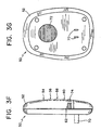
- FIG. 3A through 3G A preferred form of a receiving unit 50 is shown in Figures 3A through 3G.
- the receiving unit 50 includes a housing 52, visual indicator sets 54 through 60 and a speaker grid 62.
- Each visual indicator set, 54 through 60 includes a green light emitting diode (LED), 54A through 60A, and a red LED, 54B through 60B.
- each visual indicator set, 54 through 60 has a label area, 54C through 60C, positioned between the green and red LEDs for providing an area to designate each set of visual indicators. For example, the name of the room within the residence in which the detecting units are mounted may be written in the label area in order to identify which visual indicator set is associated with which detecting unit ( Figures 3A and 3D).
- receiving unit 50 is preferably powered via AC power provided from AC outlet 4. Accordingly, AC plug 70 is provided on the receiving unit 50, in the rear of housing 52, which engages AC outlet 4. Furthermore, receiving unit 50 includes a vent 72 also formed in the rear of housing 52 ( Figure 3G). Vent 72 permits ventilation for the electronic components contained in the receiving unit 50, which will be described in greater detail later.
- the receiving unit also includes a hush (reset) pushbutton switch 74 mounted below the sets of visual indicators on housing 52 of the receiving unit. The function of the pushbutton switch 74 will be described below.
- Each battery-powered detecting unit 20 contains electronics for generating a battery status signal and a hazardous condition alert signal.
- the battery status signal is generated and transmitted by each detecting unit 20 if the battery (or batteries) which provides power for the electronic components contained therein is at an acceptable voltage level.
- the acceptable voltage level may vary depending on the type of battery utilized in the system.
- the battery status signal is preferably periodically generated and transmitted in order to minimize the power drain on the battery powering the detecting unit 20.
- the battery status signal is generated and transmitted approximately every four (4) hours.
- the transmission duration time is preferably approximately 1 second. It is to be understood that because most detecting units of detection systems are battery-powered, the need to minimize the drain on such batteries is critical. Accordingly, by advantageously transmitting the battery status signal periodically, in accordance with the present invention, a transmitter in the detecting unit need only be operational on a periodic basis, thus conserving power and extending the lifespan of the battery.
- This unique approach of the present invention is to be contrasted with the prior art system, previously discussed, which includes an RF receiver in the detecting unit for receiving a battery test signal from a remote control unit. In such a conventional detecting unit, it is necessary to keep the receiver continuously powered in order for the receiver to always be ready to receive the battery test signal. Thus, the battery in the conventional detecting unit is continually drained, thereby severely limiting its lifespan.
- the detecting unit 20 of the present invention generates and transmits a hazardous condition alert signal.
- the alert signal is generated if a hazardous condition is detected by the detecting unit 20.
- detecting unit 20 is part of a smoke detection system, then smoke permeating through at least one of the vent openings 32 and/or grills 30 causes detecting unit 20 to generate and transmit the hazardous condition alert signal.
- the detecting unit 20 is part of a gas, flame (infrared radiation) or other type of detection system, then the permeation of such gas, infrared radiation or the like into detecting unit 20 will cause the alert signal to be generated and transmitted in a similar manner.
- the receiving unit 50 receives the battery status signals and the hazardous condition alert signals from each detecting unit 20 cooperatively operating with the receiving unit 50. It is to be appreciated that to distinguish which detecting unit 20 has transmitted which set of signals, each detecting unit 20 preferably encodes the battery status signal and alert signal with an address unique to each detecting unit 20. In addition, because a system may include more than one receiving unit 50, each detecting unit further encodes the signal transmission with an address to uniquely identify which receiving unit is adapted to receive and respond to a particular detecting unit's signals. In the same manner, the detecting unit/receiving unit address is preferably uniquely set within one detecting/receiving system so as not to interfere with a similar system of a neighboring residence.
- the receiving unit 50 decodes the encoded signal(s) and thereby determines which detecting unit 20 has transmitted the battery status signal and/or the alert signal.
- Each set of visual indicators, 54 through 60 is respectively assigned to correspond with a particular detecting unit 20. Accordingly, if the receiving unit 50 receives a battery status signal from a particular detecting unit 20 within a predetermined time period, the green LED (54A through 60A) of the respective visual indicator will illuminate, thus indicating that the battery in the particular detecting unit 20 is at an acceptable level.
- the receiving unit 50 does not receive the battery status signal from a particular detecting unit 20 within the predetermined time period, then the green LED will extinguish and the red LED (54B through 60B) of the particular visual indicator set will illuminate indicating that the battery in the detecting unit 20 is not at an acceptable level and requires replacement.
- the predetermined time period may be twelve (12) hours. This means that if the receiving unit 50 does not receive at least one battery status signal within approximately a twelve (12) hour period (a detecting unit 20 preferably transmits a battery status signal approximately once every four hours) then the receiving unit will treat such absence of signal as an indication that the battery in the detecting unit has fallen below an acceptable level.
- a timing arrangement allows for the possibility that a battery status signal may have been sent out by a detecting unit 20 within the predetermined time period but was not properly received by the receiving unit 50. Such a situation may occur due to random RF interference which may interfere with the battery status signal.
- the predetermined time period for receiving the signal includes a margin of error to attempt to avoid having the system 10 give a false indication that the battery in a particular detecting unit is below the acceptable level when, in actuality, the battery is above the level but a false indication is triggered merely due to the fact that the receiving unit erroneously fails to receive the battery status signal each time it is transmitted.
- the detecting unit 20 preferably generates a secondary status signal even after the battery status signal is no longer generated.
- the secondary status signal is preferably generated approximately two weeks after the last battery status signal is transmitted from the detecting unit 20. Similar to the battery status signal, the secondary status signal is transmitted approximately every four hours.
- the detecting unit is still able to generate and transmit the secondary status signal due to the low power requirements associated with the detecting unit and given the fact that, preferably, the battery voltage being below an acceptable level does not necessarily mean that the battery voltage is below an operable level with respect to detecting unit components.
- the secondary status signal is received by the receiving unit and, in response, the receiving unit outputs an audible warning chirp through speaker grill 62.
- the chirp warning is intended to warn the user of the system that the battery has been below the acceptable level for some time and, therefore, the battery in the detecting unit 20 should be replaced as soon as possible.
- each hazardous condition alert signal transmitted by the detecting units 20 is received and decoded by the receiving unit 50.
- the receiving unit 50 activates the set of visual indicators (54 through 60) corresponding to the detecting unit 20 which detected the hazardous condition such that both LEDs of the particular set of visual indicators begin to flash.
- an audible warning is activated through speaker grill 62 of the receiving unit 50. The audible warning provides further indication that a hazardous condition has been detected by one of the detecting units 20 in the system. It is to be appreciated that a similar audible warning may be provided by detecting unit 20 through speaker grills 30 once a hazardous condition has been detected.
- LED 34 mounted on cover 24 of detecting unit 20 preferably flashes when a hazardous condition is detected.
- the receiving unit 50 provides an area for designating which set of visual indicators correspond to which detecting unit (i.e., label areas 56C through 60C), a person may quickly determine the specific location of the hazardous condition by simply glancing at the receiving unit 50 to see which set of visual indicators is flashing. In this manner, the person need not waste valuable time in attempting to locate the condition and may instead plan an escape route from the building. Since a set of visual indicators is assigned to a particular detecting unit 20, the name of the room in which that detecting unit 20 is located may be designated on the label area, 54C through 60C, discussed above.
- the visual indicator set 54 is labeled “basement”
- the visual indicator set 56 is labeled “kitchen”
- the visual indicator set 58 is labeled “downstairs hallway”
- the visual indicator set 60 is labeled "upstairs hallway”.
- a unique audible warning may be provided by the receiving unit 50 to audibly distinguish which detecting unit 20 detected the hazardous condition and, thus, transmitted the alert signal.
- the audible warning may, for example, include a one second beep followed by a one second silent period followed by a continuous repetition of this particular pattern.
- the audible warning may include, for example, two beeps with a one second silent period followed by a continuous repetition of this particular pattern.
- the other two detecting units designated on the receiving unit 50 may provide similar unique audible patterns. In this way, a person need not even glance at the receiving unit 50 to view the flashing LEDs, but rather, can discern the location of the condition merely by listening to the audible warning pattern.
- each detecting unit 20 includes a test pushbutton switch 36.
- the test pushbutton switch 36 initiates a test of the system 10 such that, when the pushbutton switch 36 is depressed, a test hazard condition alert signal is transmitted to the receiving unit 50.
- the receiving unit receives the test signal which causes the corresponding set of visual indicators (54 through 60) for the detecting unit 20 being tested to flash as if a hazardous condition has been detected.
- the audible warning associated with the receiving unit 50 is sounded through speaker grill 62 of the receiving unit. It is also to be understood that the audible warning generated by the detecting unit 20 is also activated during this test mode and LED 34 mounted on the detecting unit will flash.
- a reset (i.e., hush) function is preferably provided on each detecting unit 20 and receiving unit 50.
- Pushbutton switch 38 on the detecting unit 20 serves to silence the alert condition (i.e., the sounding of the audible warning and flashing LED) when depressed, while the pushbutton switch 74 on the receiving unit 50 serves to silence the receiving unit's audible warning and to cease the flashing of the set of visual indicators (54 through 60).
- the hush feature may also be activated when the system 10 is providing warnings during the actual detection of a hazardous condition. However, such feature is also useful when the system 10 is set off by a condition which is not necessarily hazardous, e.g., excess smoke from cooking in a kitchen where a detecting unit 20 is installed.
- the detecting unit 20 can send a hush signal to the receiving unit 50 when the hush pushbutton switch 38 is depressed at the detecting unit 20.
- the hush signal has the same effect on the receiving unit 50 that depressing hush pushbutton switch 74 has on the receiving unit.
- the hush signal may also be used to initially set-up the system, i.e., provide an indication to the receiving unit 50 that the battery voltage is not below the acceptable level without the receiving unit having to wait for the detecting unit to periodically transmit its normal battery status signal indicating the same. This is a useful function for when the system is initially installed in a residence such that the user can immediately cause the receiving unit to indicate whether or not the battery voltage is below the acceptable level.
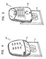
- FIG. 4 a receiving unit 50' is shown in Figure 4 which is substantially functionally and structurally the same as the receiving unit 50 previously described herein, with the exception that a nightlight 76 is provided thereon. Because the receiving unit 50' plugs into an AC outlet 4, the nightlight 76 serves to illuminate the immediate area in the vicinity of the receiving unit 50 so that it is possible to more easily read the label areas, 54C through 60C, on the visual indicator sets. It is also to be appreciated that receiving unit 50' may further include a rechargeable battery as its power source such that the receiving unit 50' may function as a flashlight when removed from the AC outlet 4. Preferably, the receiving unit 50' automatically switches over to the rechargeable battery as its source of power when removed from the AC outlet 4.
- Figure 5 illustrates a receiving unit 50" which is also similar in function and structure to receiving unit 50, but which also has a built-in AC outlet 78 which permits an AC plug from an appliance, for example, to be inserted therein and to draw power from the AC outlet 4 without removing the receiving unit 50" therefrom.
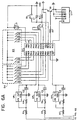
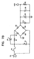
- the detecting unit circuit may be considered to include three functional subcircuits for performing the various functions described herein. Accordingly, the detecting unit circuit generally includes a sensing circuit, a battery level monitoring circuit and a transmitting circuit. Other electronic components are shown in Figures 6A and 6B which serve peripheral functions and will be discussed, as needed, to explain the novel features of the present invention.
- the sensing circuit generally includes a hazardous condition detector S0 and a detector controller U2 operatively coupled thereto. It is to be appreciated that the preferred implementation of the present invention is for smoke detection; therefore, detector S0 and controller U2 are preferably smoke detecting type devices (e.g., ionic type). However, as previously mentioned, such components may be substituted with infrared or gas (e.g., carbon monoxide) detecting devices.
- the sensing circuit also includes a microcontroller U1 and a voltage detector U6 operatively coupled between controller U2 and microcontroller U1. It is to be appreciated that, as will be explained, the microcontroller U1 is preferably programmed to provide particular functionality in all of the subcircuits of the detecting unit.
- the sensing circuit also generally includes a buzzer B 1 operatively coupled to detector controller U2.
- the battery level monitoring circuit generally includes battery BT1 and voltage detector U5 operatively coupled thereto.
- the battery BT1 is the source of power for the entire detecting unit 20 and is, therefore, being monitored to determine whether it is above or below an acceptable level.
- the voltage detector U5 is operatively coupled to the microcontroller U1 which also functions in the battery monitoring circuit, as will be explained.
- the transmitting circuit of the detecting unit generally includes microcontroller U1 operatively coupled to an oscillator XL1, a switch bank S3, a switch bank S4 and an RF module U7.
- Battery BT1 which is preferably a +9 VDC battery, is monitored by voltage detector U5.
- Voltage detector U5 in response to the voltage level of BT1, generates and provides a discrete signal to microcontroller U1.
- the discrete signal informs microcontroller U1 whether the battery BT1 is above or below an acceptable voltage level.
- the microcontroller U1 monitors the discrete signal sent by the voltage detector U6.
- Oscillator XL1 provides a clock signal to microcontroller U 1 which microcontroller U1 uses to determine when to generate and transmit a battery status signal to the receiving unit 50. As previously mentioned, it is preferred that a battery status signal be generated and transmitted every 4 hours; thus, oscillator XL1 is chosen to generate a clock signal which provides such required timing. Therefore, in accordance with the clock signal, microcontroller U1 generates the battery status signal if the discrete signal from the voltage detector U5 indicates that the battery BT1 is at an acceptable level.
- the battery status signal is encoded in order for the receiving unit 50 to determine which detecting unit 20 sent the signal. Also, the signal must be further encoded to indicate which receiving unit 50 (in a multiple receiving unit system) is to receive and respond to the battery status signal.
- Switch banks S3 and S4 provide such encoding function. Specifically, switches S 1 and S2 of switch bank S3 are used to uniquely identify each detecting unit 20 and, therefore, the signals transmitted therefrom. In a preferred system utilizing four detecting units 20 for each receiving unit 50 ( Figure 1), switches S 1 and S2 of switch bank S3 may be set to ON or OFF positions, as shown in Table I, to uniquely identify each detecting unit.
- switches A1 through A10 of switch banks S3 and S4 are used to uniquely identify the receiving unit 50 with which a particular detecting unit 20 is to operate.
- the positions of switches A1 through A10 must be set the same in each of the four detecting units 20 operating with a particular receiving unit 50 (as will be explained, the receiving unit has a similar switch bank to match the address set in the detecting unit).
- a second set of four detecting units and one receiving unit is to be operated within the broadcasting range of a first set, then, while all detecting units and receiving unit in the second set must have the same settings for switches A 1 through A10, such settings must be different as compared to the settings of A 1 through A10 in the detecting units and receiving unit ofthe first set. In this manner, only the proper receiving unit 50 will respond to its properly matched detecting units 20.
- microcontroller U1 monitors the settings of the switches of switch banks S3 and S4 and, in response, encodes the battery status signal so that it is uniquely identified with respect to the detecting unit and the receiving unit.
- the encoded battery status signal is sent to RF module U7 where it is transmitted from detecting unit 20.
- a hazardous condition such as smoke
- the smoke permeates the speaker grills 30 and/or the vent openings 32 ( Figures 2A through 2G) and is sensed by hazardous condition (smoke) detector S0.
- the detector controller U2 activates buzzer B 1 which provides the audible warning, through speaker grills 30, that the hazardous condition has been detected by the detecting unit 20.
- voltage detector U6 is monitoring detector controller U2 such that when a hazardous condition is detected by detector S0, voltage detector U6 sends a discrete signal to microcontroller U1 informing U1 of the existence of the condition.
- microcontroller U1 In a similar fashion to that described above, microcontroller U1 generates a hazardous condition alert signal which is encoded in the same manner as the battery status signal.
- the battery status signal is periodically generated and transmitted, while the alert signal is generated whenever a hazardous condition is detected. It is possible that both signals are generated within close time proximity to one another such that microcontroller U1 may generate a combined encoded status signal containing both signals.
- RF module U7 receives the encoded alert signal from microcontroller U1 and, in response, transmits the signal to receiving unit 50.
- Reset (hush) switch S 1 (shown as pushbutton 38 in Figure 2A) is operatively coupled to the microcontroller U1 and provides a reset signal to microcontroller U1 to silence the audible warning provided by the detecting unit and to extinguish LED 34 which flashes when the hazardous condition alert signal is being transmitted.
- a test pushbutton switch S2 (shown as pushbutton 36 in Figure 2A) is operatively coupled to the microcontroller U1 and provides a test signal which causes detecting unit 20 to enter a test mode to test its audible warning and to transmit a test hazardous condition alert signal to the receiving unit 50.
- Reset button S1 may preferably be able to override (e.g., cease) the test sequence once initiated by depressing test switch S2.
- a voltage regulator U3 is included in detecting unit 20 for regulating the operating voltage level provided to microcontroller U1 and RF module U7.
- a third voltage detector U4 is included in unit 20 which generates an interrupt signal which is provided to the microcontroller U1. If jumper J1 is closed, microcontroller U1 will go into a rapid test mode upon receipt of the interrupt signal whereby, instead of generating a battery status signal every four hours, the microcontroller U1 will generate a battery status signal in a shorter time period, for example, every 40 seconds.
- This feature is preferably disabled in normal operation mode and is provided basically for system troubleshooting and final production testing purposes. In other words, the user of the system would not ordinarily operate the system in this rapid test mode.
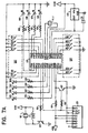
- the receiving unit circuit may be considered to include four functional subcircuits for performing the various functions described herein. As with the detecting unit circuit, several components overlap in function between subcircuits, e.g., microcontroller U21.
- the receiving unit circuit generally includes a receiving circuit, a battery status indicating circuit, a hazardous condition alert circuit and a power supply circuit. Again, other electronic components are shown in Figure 7A and 7B which serve peripheral functions and will be discussed, as needed, to explain the novel features of the present invention.
- the power supply circuit includes AC plug 70 ( Figures 3A through 3G), capacitors C21 through C23, fuse F21, resistors R21 and R22, thyristor device Z21, diode bridge, D21 through D24, and Zener diode ZD1.
- Such power supply circuit operates as a conventional full wave bridge rectifier circuit and converts the AC power supplied by the AC outlet 4 ( Figure 3B), in which AC plug 70 is inserted, to a DC voltage, V DD , which is utilized by the electronic components of the receiving unit 50.
- the receiving circuit generally includes an RF receiver module U23 operatively coupled to a microcontroller U21 and switch banks S21' and S22' also operatively coupled to the microcontroller U21.
- microcontroller U21 in receiving unit 50 is preferably programmed to provide particular functionality in the receiving, battery level indicating and hazardous condition alert circuits.
- the battery status indicating circuit generally includes microcontroller U21, diodes D25 through D32, operatively coupled to microcontroller U21 through resistors R26 through R33, a buzzer B21 and a coil L21 operatively coupled through a transistor Q22 to microcontroller U21.
- the battery status indicating circuit also includes oscillator XL1 operatively coupled to microcontroller U21.
- the hazardous condition alert circuit generally consists of microcontroller U21 and buzzer B21 and coil L21 operatively coupled to microcontroller U21 through transistor Q22.
- RF module U23 receives an encoded battery status signal from one of the detecting units 20.
- the received signal is provided to the microcontroller U21 wherein, in accordance with the settings of switch banks S21' and S22', the signal is decoded.
- Microcontroller U21 will only respond to signals which are encoded by detecting units 20 in which the settings of switches A1 through A10 of switch banks S3 and S4 ( Figure 6) are set the same way as switches A21 through A30 of switch banks S21' and S22' in receiving unit 50.
- this unique address matching scheme is provided to permit multiple systems (e.g., two systems having one receiving unit and four detecting units) to operate within a common RF broadcasting area.
- microcontroller U21 determines that it is the receiving unit set to receive the signal, microcontroller U21 further decodes the received signal to determine which of the four detecting units sent the signal. As previously explained, such identification is uniquely set by switches S1 and S2 of switch bank S3 of the detecting unit 20.
- LED's D25 through D32 comprise the visual indicator sets 54 through 60 ( Figures 3A through 3G).
- D25 is a red LED (54B) and D29 is a green LED (54A) and together they make up visual indicator set 54.
- D26 red LED 56B
- D30 green LED 56A
- D27 red LED 58B
- D31 green LED 58A
- D28 red LED60B
- D32 green LED 60A
- Microcontroller U21 assigns one of the four visual indicator sets, 54 through 60, to one of the four detecting units 20 and can determine which detecting unit 20 sent which signal by decoding the two bit address encoded in the signal by switches S1 and S2 of switchbank S3 of the detecting unit 20. Furthermore, switches S21 and S22 of switchbank S21' of the receiving unit 50 may be utilized to selectively disable each set of visual indicators which is not assigned to a particular detecting unit, e.g., in a system with less than four detecting units in operation. The switches S21 and S22 of switch bank S21' ( Figure 7A) may be set as shown in Table II, depending on how many detecting units 20 are operating with the receiving unit 50.
- microcontroller U21 receives the battery status signals through RF module U23 and, via their unique addresses, decodes the signals and then respectively illuminates each green LED (D29 through D32) if a battery status signal is received for that particular detecting unit 20. If a battery status signal is not received from a particular detecting unit 20 within a predetermined time period (set by a clock signal generated by oscillator XL1), then microcontroller U21 will extinguish the corresponding green LED and illuminate the corresponding red LED. As previously mentioned, the predetermined time period is preferably 12 hours. In this manner, a person need only glance at the receiving unit 50 to determine if the green LED or red LED is illuminated for a particular detecting unit 20. If the red LED is illuminated, he will know to change the battery in the corresponding detecting unit 20.
- RF module U23 may receive a hazardous condition alert signal transmitted by one of the four detecting units 20.
- the microcontroller U21 decodes the signal and, based on whether or not there is an address match between switches A21 through A30 of the detecting and receiving units, the microcontroller U21 will further decode the signal to determine from which detecting unit the signal was transmitted.
- the microcontroller U21 causes the set of visual indicators (56 through 60) corresponding to the detecting unit 20 that sent the hazardous condition alert signal to continually flash. This visual warning gives a person an indication as to which detecting unit 20 detected the condition and, thus, gives him an opportunity to act accordingly.
- microcontroller U21 activates buzzer B21 through transistor Q22 and coil L21 Similar to buzzer B21 in detecting unit 20, buzzer B21 in receiving unit 50 sounds an audible warning when an alert signal is received. Also, in a preferred embodiment, microcontroller U21 may cause buzzer B21 to sound a unique warning pattern depending on which detecting unit 20 detected the hazardous condition.
- hush (reset) pushbutton switch 74 is not expressly shown in Figure 7, it is to be appreciated that such switch operates in a similar manner to the reset switch S1 (pushbutton 38) shown in Figure 6A for the detecting unit, i.e., depressing reset pushbutton ceases alarm condition and, therefore, ceases flashing visual indicators and silences buzzer B21.
- a hush pushbutton switch may be included on the detecting unit 20 only and, when depressed, the detecting unit 20 transmits a reset signal, encoded in the manner described herein, to reset the receiving unit 50.
- Voltage detector U22 shown in Figure 7A operatively coupled to microcontroller U21, is preferably provided to generate a microcontroller reset signal upon power-up of the receiving unit 50, e.g., when the unit is plugged into AC outlet 4.
- the microcontroller reset signal resets the microcontroller U1 upon power-up.
- a parts list for the detecting circuit in Figures 6A and 6B is provided below in Table III, while a parts list for the receiving circuit in Figures 7A and 7B is provided below in Table IV. Additionally, the pin name designations on the integrated circuits in Figures 6 and 7 relate to parts specified in the parts list. It is envisioned that components comparable to those listed below, connected differently from that shown in Figures 6 and 7, may be suitable to practice the present invention.
- PARTS LIST FOR ELECTRONIC CIRCUIT ILLUSTRATED IN FIGURES 6 A and B Reference Numeral Part Identification Value/Part No.
- a system 10' is formed by at least one detecting unit 20, at least one receiving unit 50 and a building security system 80.
- the at least one detecting unit 20 transmits a hazardous condition alert signal to the building security system 80 in addition to the receiving unit 50 as described herein.
- the security system 80 may serve the primary purpose of alerting a security system monitoring company or local authorities of an intruder or other security condition over telephone line 82.
- the security system 80 also preferably includes receiving means similar to the at least one receiving unit 50 which receives the hazardous condition alert signal from the at least one detecting unit 20.
- the security system 80 may then communicate the existence of the hazardous condition within the building in which the system 10' is operating to the monitoring company and/or local authorities over line 82. In this manner, the present invention provides a passive system for detecting hazardous conditions and automatically reporting their existence to emergency personnel. It is to be understood that security system 80 may preferably be responsive to all detecting units 20 within a building whether or not the detecting units 20 cooperate with different receiving units 50.
Landscapes
- Engineering & Computer Science (AREA)
- Computer Security & Cryptography (AREA)
- Physics & Mathematics (AREA)
- General Physics & Mathematics (AREA)
- Alarm Systems (AREA)
- Fire Alarms (AREA)
- Selective Calling Equipment (AREA)
- Burglar Alarm Systems (AREA)
- Emergency Alarm Devices (AREA)
- Tests Of Electric Status Of Batteries (AREA)
Claims (34)
- Système pour détecter l'existence d'une condition hasardeuse dans une région, le système comportant :au moins une unité de détection alimentée par batterie (20) placée dans la région (2A, 2B, 2C, 2D) pour détecter l'existence de la condition hasardeuse, la au moins une unité de détection alimentée par batterie (20) générant et transmettant un signal d'état de batterie uniquement si l'énergie de la batterie est au moins égale à un niveau acceptable, conservant ainsi l'énergie de la batterie, etau moins une unité de réception (50) sensible au signal d'état de batterie de sorte que la au moins une unité de réception (50) délivre au moins une indication sensorielle lorsque le signal d'état de batterie n'est pas reçu dans une période de temps prédéterminée.
- Système selon la revendication 1, dans lequel la au moins une unité de détection alimentée par batterie (20) transmet périodiquement le signal d'état de batterie.
- Système selon la revendication 1, incluant en outre une pluralité d'unités de détection alimentées par batterie (20) placées respectivement dans une pluralité de zones dans la région (2A, 2B, 2C, 2D) de sorte que chaque unité de détection (29) génère èt transmet un signal d'état de batterie de telle sorte que la au moins une unité de réception (50) délivre en réponse l'une parmi une pluralité d'indications sensorielles lorsque l'un parmi la pluralité de signaux d'état de batterie n'est pas respectivement reçu.
- Système selon la revendication 1, dans lequel la au moins une unité de réception (50) délivre une première indication sensorielle lorsque le signal d'état de batterie est reçu et une seconde indication sensorielle lorsque le signal d'état de batterie n'est pas reçu.
- Système selon la revendication 4, comportant en outre un premier indicateur (54A à 60A) monté sur la au moins une unité de réception (50) pour délivrer la première indication sensorielle et un second indicateur (54B à 60B) monté sur la au moins une unité de réception (50) pour délivrer la seconde indication sensorielle.
- Système selon la revendication 5, dans lequel les premier et second indicateurs (54A à 60A, 54B à 60B) sont des diodes électroluminescentes.
- Système selon la revendication 6, dans lequel les première et seconde diodes électroluminescentes sont chacune d'une couleur différente.
- Système selon la revendication 1, dans lequel la au moins une indication sensorielle délivrée par la au moins une unité de réception (50) délivre également une indication indiquant que l'existence de la condition hasardeuse a été détectée par la au moins une unité de détection (20).
- Système selon la revendication 8, dans lequel la au moins une indication sensorielle est délivrée par un indicateur visuel.
- Système selon la revendication 1, dans lequel la au moins une unité de réception (50) inclut en outre au moins une indication sensorielle de signal d'alerte pour indiquer que l'existence de la condition hasardeuse a été détectée par la au moins une unité de détection (20).
- Système selon la revendication 10, dans lequel la seconde indication sensorielle est délivrée par un indicateur audible.
- Système selon la revendication 11, dans lequel la au moins une unité de réception (50) inclut en outre des moyens pour rendre silencieux l'indicateur audible.
- Système selon la revendication 1, dans lequel la au moins une unité de réception (50) inclut en outre une source de lumière, fonctionnellement connectée à la au moins une unité de réception (50) pour éclairer une région à proximité de la au moins une unité de réception (50).
- Système selon la revendication 1, dans lequel la au moins une unité de réception (50) inclut en outre une source d'énergie (78) adaptée pour être commandée via l'énergie provenant d'une sortie d'énergie à courant alternatif (AC) (4).
- Système selon la revendication 1, dans lequel la au moins une unité de réception (50) inclut en outre une batterie rechargeable (BT1) pour fournir une source d'énergie à l'unité.
- Système selon la revendication 15, dans lequel la au moins une unité de réception (50) inclut en outre une source de lumière (76) fonctionnellement connectée à la au moins une unité de réception (50) pour permettre à la au moins une unité de réception (50) d'être utilisée en tant que dispositif d'éclairage portable.
- Système selon la revendication 1, dans lequel la au moins une unité de détection (20) inclut en outre un circuit émetteur de fréquence radio pour transmettre le signal d'état de batterie.
- Système selon la revendication 17, dans lequel la au moins une unité de réception (50) inclut en outre un circuit récepteur de fréquence radio pour recevoir le signal d'état de batterie.
- Système pour détecter l'existence d'une condition hasardeuse dans une région selon la revendication 1, le système comportant :une pluralité d'unités de détection alimentées par batterie (20), chaque unité de détection (20) étant placée respectivement dans une pluralité de zones (2A, 2B, 2C, 2D) dans la région, chaque unité de détection (20) incluant :un circuit de détection, le circuit de détection détectant l'existence de la condition hasardeuse dans la zone respective (2A, 2B, 2C, 2D) et générant un signal d'alerte de condition hasardeuse en réponse à celle-ci,un circuit de surveillance de niveau de batterie, le circuit de surveillance de niveau de batterie surveillant le niveau de la batterie alimentant l'unité de détection (20) et générant un signal d'état de batterie uniquement lorsque l'énergie de la batterie est au moins égale à un niveau acceptable, etun circuit de transmission, le circuit de transmission transmettant au moins l'un parmi le signal d'alerte de condition hasardeuse et le signal d'état de batterie, etau moins une unité de réception (50), la au moins une unité de réception étant sensible à la pluralité d'unités de détection et incluant :un circuit de réception, le circuit de réception recevant l'un parmi la pluralité de signaux d'alerte de condition hasardeuse et la pluralité de signaux d'état de batterie,un circuit d'indication d'état de batterie, le circuit d'indication d'état de batterie étant sensible à la pluralité de signaux d'état de batterie, le circuit d'indication d'état de batterie incluant une pluralité d'indicateurs visuels (54 à 60) qui sont respectivement sensibles à la pluralité de signaux d'état de batterie de sorte que chaque indicateur (54 à 60) délivre une première indication visuelle lorsque le signal d'état de batterie respectif qui lui correspond est reçu et une seconde indication visuelle lorsque le signal d'état de batterie respectif n'est pas reçu dans une période de temps prédéterminée, etun circuit d'alerte de condition hasardeuse, le circuit d'alerte étant sensible à la pluralité de signaux d'alerte de condition hasardeuse de sorte que le circuit d'alerte active respectivement les indicateurs visuels (54 à 60) correspondant à l'une des unités de détection (20) lorsqu'un signal d'alerte est reçu à partir de ces dernières.
- Système selon la revendication 19, dans lequel la au moins une unité de réception (50) inclut en outre au moins un indicateur audible qui délivre une indication audible en réponse à la pluralité de signaux d'alerte reçus par la au moins une unité de réception (50).
- Système selon la revendication 20, dans lequel une indication audible unique est délivrée par le au moins un indicateur audible pour chacun de la pluralité de signaux d'alerte.
- Système selon la revendication 20, dans lequel la au moins une unité de réception (50) inclut en outre des moyens pour rendre silencieux le au moins un indicateur audible.
- Système selon la revendication 19, dans lequel chacun de la pluralité de signaux d'état de batterie est transmis périodiquement.
- Système selon la revendication 19, dans lequel le circuit d'indication d'état de batterie inclut en outre une pluralité de paires d'indicateurs visuels (54A à 60A, 54B à 60B) où chaque paire inclut un premier indicateur pour délivrer la première indication visuelle et un second indicateur pour délivrer la seconde indication visuelle.
- Système selon la revendication 24, dans lequel les premier et second indicateurs sont d'une couleur différente.
- Système selon la revendication 25, dans lequel les premier et second indicateurs (54A à 60A, 54B à 60B) sont des diodes électroluminescentes.
- Système selon la revendication 19, dans lequel la au moins une unité de réception inclut en outre une source de lumière, fonctionnellement connectée à la au moins une unité de réception pour éclairer une région à proximité de la au moins une unité de réception.
- Système selon la revendication 19, dans lequel la au moins une unité de réception (50") inclut en outre une source d'énergie (78) adaptée pour être commandée via l'énergie provenant d'une sortie d'énergie AC (4).
- Système selon la revendication 19, dans lequel la au moins une unité de réception (50) inclut en outre une batterie rechargeable (BT1) pour délivrer une source d'énergie à l'unité.
- Système selon la revendication 29, dans lequel la au moins une unité de réception inclut en outre une source de lumière (76) fonctionnellement connectée à la au moins une unité de réception (50') pour permettre à la au moins une unité de réception (50') d'être utilisée en tant que dispositif d'éclairage portable.
- Système selon la revendication 19, dans lequel le circuit de transmission de chacune de la pluralité d'unités de détection (20) inclut des moyens pour coder d'une manière unique l'un parmi le signal d'alerte de condition hasardeuse et le signal d'état de batterie afin d'identifier d'une manière unique le signal.
- Système selon la revendication 31, dans lequel le circuit de réception inclut en outre des moyens pour décoder l'un de chacun des signaux d'état de batterie et des signaux d'alerte de condition hasardeuse pour déterminer laquelle de la pluralité d'unités de détection (20) a transmis le signal reçu.
- Procédé pour surveiller un niveau de tension associé à une batterie d'une unité de détection alimentée par batterie, l'unité de détection détectant l'existence d'une condition hasardeuse dans une région, le procédé comportant les étapes consistant à :générer un signal d'état de batterie lorsque la batterie de l'unité de détection est au moins égale à un niveau acceptable,transmettre le signal d'état de batterie à partir de l'unité de détection uniquement lorsque la batterie de l'unité détectée est au moins égale au niveau acceptable, conservant ainsi l'énergie de la batterie,surveiller le signal d'état de batterie dans une unité de réception, l'unité de réception incluant un indicateur sensoriel, etactiver l'indicateur sensoriel lorsque le signal d'état de batterie n'est pas reçu par l'unité de réception dans une période de temps prédéterminée.
- Procédé selon la revendication 33, incluant en outre les étapes consistant à :générer un signal d'alerte de condition hasardeuse lorsque l'existence de la condition hasardeuse est détectée par le circuit de détection,transmettre le signal d'alerte depuis l'unité de détection,surveiller le signal d'alerte dans une unité de réception, etactiver l'indicateur sensoriel lorsque le signal d'alerte de condition hasardeuse est reçu.
Applications Claiming Priority (3)
| Application Number | Priority Date | Filing Date | Title |
|---|---|---|---|
| US08/781,668 US5905438A (en) | 1997-01-10 | 1997-01-10 | Remote detecting system and method |
| US781668 | 1997-01-10 | ||
| PCT/US1998/000286 WO1998030987A2 (fr) | 1997-01-10 | 1998-01-09 | Systeme et procede de teledetection |
Publications (3)
| Publication Number | Publication Date |
|---|---|
| EP1012801A2 EP1012801A2 (fr) | 2000-06-28 |
| EP1012801A4 EP1012801A4 (fr) | 2001-03-14 |
| EP1012801B1 true EP1012801B1 (fr) | 2003-11-26 |
Family
ID=25123517
Family Applications (1)
| Application Number | Title | Priority Date | Filing Date |
|---|---|---|---|
| EP98902422A Expired - Lifetime EP1012801B1 (fr) | 1997-01-10 | 1998-01-09 | Systeme et procede de teledetection |
Country Status (5)
| Country | Link |
|---|---|
| US (1) | US5905438A (fr) |
| EP (1) | EP1012801B1 (fr) |
| AT (1) | ATE255257T1 (fr) |
| DE (1) | DE69820079D1 (fr) |
| WO (1) | WO1998030987A2 (fr) |
Families Citing this family (307)
| Publication number | Priority date | Publication date | Assignee | Title |
|---|---|---|---|---|
| US6933833B1 (en) * | 1987-10-14 | 2005-08-23 | Universal Electronics Inc. | Remote control with LED capabilities |
| IT1279591B1 (it) * | 1995-05-12 | 1997-12-16 | Marposs Spa | Sistema e metodo di trasmissione di segnali via etere per sonde di controllo |
| US7054271B2 (en) | 1996-12-06 | 2006-05-30 | Ipco, Llc | Wireless network system and method for providing same |
| US8982856B2 (en) | 1996-12-06 | 2015-03-17 | Ipco, Llc | Systems and methods for facilitating wireless network communication, satellite-based wireless network systems, and aircraft-based wireless network systems, and related methods |
| US7079810B2 (en) | 1997-02-14 | 2006-07-18 | Statsignal Ipc, Llc | System and method for communicating with a remote communication unit via the public switched telephone network (PSTN) |
| US6233327B1 (en) | 1997-02-14 | 2001-05-15 | Statsignal Systems, Inc. | Multi-function general purpose transceiver |
| US7137550B1 (en) | 1997-02-14 | 2006-11-21 | Statsignal Ipc, Llc | Transmitter for accessing automated financial transaction machines |
| US6914893B2 (en) | 1998-06-22 | 2005-07-05 | Statsignal Ipc, Llc | System and method for monitoring and controlling remote devices |
| US6914533B2 (en) | 1998-06-22 | 2005-07-05 | Statsignal Ipc Llc | System and method for accessing residential monitoring devices |
| US6437692B1 (en) | 1998-06-22 | 2002-08-20 | Statsignal Systems, Inc. | System and method for monitoring and controlling remote devices |
| US6891838B1 (en) | 1998-06-22 | 2005-05-10 | Statsignal Ipc, Llc | System and method for monitoring and controlling residential devices |
| US8410931B2 (en) | 1998-06-22 | 2013-04-02 | Sipco, Llc | Mobile inventory unit monitoring systems and methods |
| US7103511B2 (en) | 1998-10-14 | 2006-09-05 | Statsignal Ipc, Llc | Wireless communication networks for providing remote monitoring of devices |
| US6144310A (en) * | 1999-01-26 | 2000-11-07 | Morris; Gary Jay | Environmental condition detector with audible alarm and voice identifier |
| US6768424B1 (en) | 1999-01-21 | 2004-07-27 | Gary J. Morris | Environmental condition detector with remote fire extinguisher locator system |
| US6747557B1 (en) * | 1999-03-18 | 2004-06-08 | Statsignal Systems, Inc. | System and method for signaling a weather alert condition to a residential environment |
| US7650425B2 (en) | 1999-03-18 | 2010-01-19 | Sipco, Llc | System and method for controlling communication between a host computer and communication devices associated with remote devices in an automated monitoring system |
| US7263073B2 (en) | 1999-03-18 | 2007-08-28 | Statsignal Ipc, Llc | Systems and methods for enabling a mobile user to notify an automated monitoring system of an emergency situation |
| US20040183687A1 (en) * | 1999-03-18 | 2004-09-23 | Petite Thomas D. | System and method for signaling a weather alert condition to a residential environment |
| US6646559B2 (en) * | 2000-08-29 | 2003-11-11 | User-Centric Enterprises, Inc. | Method and apparatus for activating warning devices |
| US6616333B2 (en) | 2000-09-22 | 2003-09-09 | Kraft Foods Holdings, Inc. | Fastener closure arrangement for flexible packages |
| CA2432805C (fr) * | 2000-12-07 | 2006-10-17 | Raymond Bellone | Systeme d'alerte a declenchements multiples par emetteurs et recepteur-vibreur portable |
| US6762688B2 (en) * | 2001-02-16 | 2004-07-13 | Brk Brands, Inc. | Device with silencing circuitry |
| SE519176C2 (sv) * | 2001-06-13 | 2003-01-28 | E2 Home Ab | Förfarande och system för styrning och underhåll av servicenät för hemmet |
| JP3671891B2 (ja) * | 2001-10-04 | 2005-07-13 | オムロン株式会社 | センサネットワークシステム管理方法、センサネットワークシステム管理プログラム、センサネットワークシステム管理プログラムを記録した記録媒体、およびセンサネットワークシステム管理装置 |
| US8489063B2 (en) | 2001-10-24 | 2013-07-16 | Sipco, Llc | Systems and methods for providing emergency messages to a mobile device |
| US7480501B2 (en) | 2001-10-24 | 2009-01-20 | Statsignal Ipc, Llc | System and method for transmitting an emergency message over an integrated wireless network |
| US7424527B2 (en) | 2001-10-30 | 2008-09-09 | Sipco, Llc | System and method for transmitting pollution information over an integrated wireless network |
| US6642849B1 (en) * | 2001-12-11 | 2003-11-04 | Maple Chase Company | Hush disable feature for photoelectric smoke alarm |
| US6658091B1 (en) | 2002-02-01 | 2003-12-02 | @Security Broadband Corp. | LIfestyle multimedia security system |
| US7769617B2 (en) * | 2002-10-29 | 2010-08-03 | Tokyo Electron Limited | Worker management system, worker management apparatus and worker management method |
| US20040142662A1 (en) * | 2003-01-21 | 2004-07-22 | Thomas Ehrenberg | Remote change of status signal device |
| NL1022496C2 (nl) * | 2003-01-27 | 2004-07-28 | Sensite Solutions B V | Werkwijze voor het vaststellen van het beschikbare vermogen van een voedingsbron in een zender van een tracerings- en telemetriesysteem, alsmede een zender, een ontvanger en een dergelijk systeem. |
| US20060132302A1 (en) * | 2003-02-03 | 2006-06-22 | Stilp Louis A | Power management of transponders and sensors in an RFID security network |
| US7119658B2 (en) * | 2003-02-03 | 2006-10-10 | Ingrid, Inc. | Device enrollment in a security system |
| US7091827B2 (en) * | 2003-02-03 | 2006-08-15 | Ingrid, Inc. | Communications control in a security system |
| US7057512B2 (en) * | 2003-02-03 | 2006-06-06 | Ingrid, Inc. | RFID reader for a security system |
| US7283048B2 (en) * | 2003-02-03 | 2007-10-16 | Ingrid, Inc. | Multi-level meshed security network |
| US7532114B2 (en) * | 2003-02-03 | 2009-05-12 | Ingrid, Inc. | Fixed part-portable part communications network for a security network |
| US7042353B2 (en) * | 2003-02-03 | 2006-05-09 | Ingrid, Inc. | Cordless telephone system |
| US7079020B2 (en) * | 2003-02-03 | 2006-07-18 | Ingrid, Inc. | Multi-controller security network |
| US7511614B2 (en) * | 2003-02-03 | 2009-03-31 | Ingrid, Inc. | Portable telephone in a security network |
| US7019639B2 (en) * | 2003-02-03 | 2006-03-28 | Ingrid, Inc. | RFID based security network |
| US7053764B2 (en) * | 2003-02-03 | 2006-05-30 | Ingrid, Inc. | Controller for a security system |
| US7079034B2 (en) * | 2003-02-03 | 2006-07-18 | Ingrid, Inc. | RFID transponder for a security system |
| US7495544B2 (en) * | 2003-02-03 | 2009-02-24 | Ingrid, Inc. | Component diversity in a RFID security network |
| US6888459B2 (en) * | 2003-02-03 | 2005-05-03 | Louis A. Stilp | RFID based security system |
| US7023341B2 (en) * | 2003-02-03 | 2006-04-04 | Ingrid, Inc. | RFID reader for a security network |
| US20040215750A1 (en) * | 2003-04-28 | 2004-10-28 | Stilp Louis A. | Configuration program for a security system |
| AU2003233813A1 (en) * | 2003-05-29 | 2005-01-21 | Tsk Electronica Y Electricidad, S.A. | Electronic equipment for remote monitoring of installations |
| ES2257222B1 (es) * | 2003-05-29 | 2007-11-16 | Tsk Electronica Y Electricidad, S.A. | Equipo electronico de supervision remota de instalaciones. |
| US7030766B2 (en) * | 2003-06-18 | 2006-04-18 | Edwards Systems Technology, Inc. | Ambient condition detector with multi-function test |
| US7098785B2 (en) * | 2003-10-30 | 2006-08-29 | Cosco Management, Inc. | Juvenile monitoring system |
| US20050128093A1 (en) * | 2003-12-16 | 2005-06-16 | Genova James J. | Self-protected fire-sensing alarm apparatus and method |
| WO2005069240A2 (fr) * | 2003-12-22 | 2005-07-28 | Dunstan Walter Runciman | Detecteur d'incendie |
| US8031650B2 (en) | 2004-03-03 | 2011-10-04 | Sipco, Llc | System and method for monitoring remote devices with a dual-mode wireless communication protocol |
| US7756086B2 (en) | 2004-03-03 | 2010-07-13 | Sipco, Llc | Method for communicating in dual-modes |
| US11113950B2 (en) | 2005-03-16 | 2021-09-07 | Icontrol Networks, Inc. | Gateway integrated with premises security system |
| US11159484B2 (en) | 2004-03-16 | 2021-10-26 | Icontrol Networks, Inc. | Forming a security network including integrated security system components and network devices |
| US10382452B1 (en) | 2007-06-12 | 2019-08-13 | Icontrol Networks, Inc. | Communication protocols in integrated systems |
| US11244545B2 (en) | 2004-03-16 | 2022-02-08 | Icontrol Networks, Inc. | Cross-client sensor user interface in an integrated security network |
| US10142392B2 (en) | 2007-01-24 | 2018-11-27 | Icontrol Networks, Inc. | Methods and systems for improved system performance |
| US9609003B1 (en) | 2007-06-12 | 2017-03-28 | Icontrol Networks, Inc. | Generating risk profile using data of home monitoring and security system |
| US10200504B2 (en) | 2007-06-12 | 2019-02-05 | Icontrol Networks, Inc. | Communication protocols over internet protocol (IP) networks |
| US20170118037A1 (en) | 2008-08-11 | 2017-04-27 | Icontrol Networks, Inc. | Integrated cloud system for premises automation |
| US12063220B2 (en) | 2004-03-16 | 2024-08-13 | Icontrol Networks, Inc. | Communication protocols in integrated systems |
| US11368429B2 (en) | 2004-03-16 | 2022-06-21 | Icontrol Networks, Inc. | Premises management configuration and control |
| US9141276B2 (en) | 2005-03-16 | 2015-09-22 | Icontrol Networks, Inc. | Integrated interface for mobile device |
| US7711796B2 (en) | 2006-06-12 | 2010-05-04 | Icontrol Networks, Inc. | Gateway registry methods and systems |
| US8963713B2 (en) | 2005-03-16 | 2015-02-24 | Icontrol Networks, Inc. | Integrated security network with security alarm signaling system |
| US11277465B2 (en) | 2004-03-16 | 2022-03-15 | Icontrol Networks, Inc. | Generating risk profile using data of home monitoring and security system |
| US11489812B2 (en) | 2004-03-16 | 2022-11-01 | Icontrol Networks, Inc. | Forming a security network including integrated security system components and network devices |
| US11811845B2 (en) | 2004-03-16 | 2023-11-07 | Icontrol Networks, Inc. | Communication protocols over internet protocol (IP) networks |
| US9531593B2 (en) | 2007-06-12 | 2016-12-27 | Icontrol Networks, Inc. | Takeover processes in security network integrated with premise security system |
| US11343380B2 (en) | 2004-03-16 | 2022-05-24 | Icontrol Networks, Inc. | Premises system automation |
| US8335842B2 (en) | 2004-03-16 | 2012-12-18 | Icontrol Networks, Inc. | Premises management networking |
| US11316958B2 (en) | 2008-08-11 | 2022-04-26 | Icontrol Networks, Inc. | Virtual device systems and methods |
| US10348575B2 (en) | 2013-06-27 | 2019-07-09 | Icontrol Networks, Inc. | Control system user interface |
| US10313303B2 (en) | 2007-06-12 | 2019-06-04 | Icontrol Networks, Inc. | Forming a security network including integrated security system components and network devices |
| US11677577B2 (en) | 2004-03-16 | 2023-06-13 | Icontrol Networks, Inc. | Premises system management using status signal |
| US10339791B2 (en) | 2007-06-12 | 2019-07-02 | Icontrol Networks, Inc. | Security network integrated with premise security system |
| US10522026B2 (en) | 2008-08-11 | 2019-12-31 | Icontrol Networks, Inc. | Automation system user interface with three-dimensional display |
| US10375253B2 (en) | 2008-08-25 | 2019-08-06 | Icontrol Networks, Inc. | Security system with networked touchscreen and gateway |
| US20090077623A1 (en) | 2005-03-16 | 2009-03-19 | Marc Baum | Security Network Integrating Security System and Network Devices |
| US11916870B2 (en) | 2004-03-16 | 2024-02-27 | Icontrol Networks, Inc. | Gateway registry methods and systems |
| US8988221B2 (en) | 2005-03-16 | 2015-03-24 | Icontrol Networks, Inc. | Integrated security system with parallel processing architecture |
| US10444964B2 (en) | 2007-06-12 | 2019-10-15 | Icontrol Networks, Inc. | Control system user interface |
| US9191228B2 (en) | 2005-03-16 | 2015-11-17 | Icontrol Networks, Inc. | Cross-client sensor user interface in an integrated security network |
| US11582065B2 (en) | 2007-06-12 | 2023-02-14 | Icontrol Networks, Inc. | Systems and methods for device communication |
| US8635350B2 (en) | 2006-06-12 | 2014-01-21 | Icontrol Networks, Inc. | IP device discovery systems and methods |
| US9729342B2 (en) | 2010-12-20 | 2017-08-08 | Icontrol Networks, Inc. | Defining and implementing sensor triggered response rules |
| US10721087B2 (en) | 2005-03-16 | 2020-07-21 | Icontrol Networks, Inc. | Method for networked touchscreen with integrated interfaces |
| US11201755B2 (en) | 2004-03-16 | 2021-12-14 | Icontrol Networks, Inc. | Premises system management using status signal |
| US10156959B2 (en) | 2005-03-16 | 2018-12-18 | Icontrol Networks, Inc. | Cross-client sensor user interface in an integrated security network |
| US10237237B2 (en) | 2007-06-12 | 2019-03-19 | Icontrol Networks, Inc. | Communication protocols in integrated systems |
| US7084775B1 (en) * | 2004-07-12 | 2006-08-01 | User-Centric Ip, L.P. | Method and system for generating and sending user-centric weather alerts |
| US20060055548A1 (en) * | 2004-09-13 | 2006-03-16 | Ki Deog Kong | Smoke detecting system having self-monitoring function |
| US7218238B2 (en) * | 2004-09-24 | 2007-05-15 | Edwards Systems Technology, Inc. | Fire alarm system with method of building occupant evacuation |
| WO2006044750A2 (fr) * | 2004-10-18 | 2006-04-27 | Walter Kidde Portable Equipment, Inc. | Suppression d'alarme de batterie faible dans des dispositifs de securite des personnes |
| EP1803106B1 (fr) * | 2004-10-18 | 2010-03-17 | Walter Kidde Portable Equipment, Inc. | Dispositif de passerelle permettant d'interconnecter un systeme comprenant des dispositifs de securite des personnes |
| DE602005027374D1 (de) * | 2004-10-18 | 2011-05-19 | Kidde Portable Equipment Inc | Frequenzkommunikationsschema in lebenserhaltenden vorrichtungen |
| US20060097885A1 (en) * | 2004-10-27 | 2006-05-11 | Sengupta Uttam K | Methods and apparatus for providing a power dashboard system |
| US20060238330A1 (en) * | 2004-11-02 | 2006-10-26 | Ihs Imonitoring Inc. | Adaptable wireless sensor |
| USD541689S1 (en) | 2005-01-13 | 2007-05-01 | Broan-Nutone Llc | Doorbell chime cover |
| USD567692S1 (en) | 2005-01-13 | 2008-04-29 | Broan-Nutone Llc | Display doorbell chime cover |
| US9439126B2 (en) | 2005-01-25 | 2016-09-06 | Sipco, Llc | Wireless network protocol system and methods |
| US11615697B2 (en) | 2005-03-16 | 2023-03-28 | Icontrol Networks, Inc. | Premise management systems and methods |
| US20120324566A1 (en) | 2005-03-16 | 2012-12-20 | Marc Baum | Takeover Processes In Security Network Integrated With Premise Security System |
| US20150054947A1 (en) | 2005-03-16 | 2015-02-26 | Paul J. Dawes | Device for data routing in networks |
| US9306809B2 (en) | 2007-06-12 | 2016-04-05 | Icontrol Networks, Inc. | Security system with networked touchscreen |
| US20110128378A1 (en) | 2005-03-16 | 2011-06-02 | Reza Raji | Modular Electronic Display Platform |
| US10999254B2 (en) | 2005-03-16 | 2021-05-04 | Icontrol Networks, Inc. | System for data routing in networks |
| US11700142B2 (en) | 2005-03-16 | 2023-07-11 | Icontrol Networks, Inc. | Security network integrating security system and network devices |
| US11496568B2 (en) | 2005-03-16 | 2022-11-08 | Icontrol Networks, Inc. | Security system with networked touchscreen |
| US20170180198A1 (en) | 2008-08-11 | 2017-06-22 | Marc Baum | Forming a security network including integrated security system components |
| GB2430062A (en) * | 2005-09-09 | 2007-03-14 | Royal Nat Lifeboat Institution | Marine crew security system using message passing between base station and personal safety transceivers. |
| US8847772B2 (en) * | 2005-10-12 | 2014-09-30 | Mitchell J. Marks | Smoke detector with remote alarm silencing means |
| US7852209B2 (en) * | 2006-01-30 | 2010-12-14 | Honeywell International Inc. | Intelligent occupancy monitoring using premises network |
| US7710256B2 (en) * | 2006-02-23 | 2010-05-04 | Honeywell International Inc. | Method and apparatus for audio assisted testing |
| USD644350S1 (en) | 2006-03-23 | 2011-08-30 | Kadence Designs, LLC | Speaker light bulb |
| USD644351S1 (en) | 2006-03-23 | 2011-08-30 | Kadence Designs, LLC | Speaker light bulb |
| US7535341B2 (en) * | 2006-03-23 | 2009-05-19 | Haase Edward H | Combination speaker / light fixture |
| US12063221B2 (en) | 2006-06-12 | 2024-08-13 | Icontrol Networks, Inc. | Activation of gateway device |
| US10079839B1 (en) | 2007-06-12 | 2018-09-18 | Icontrol Networks, Inc. | Activation of gateway device |
| US7515058B2 (en) * | 2006-06-16 | 2009-04-07 | William Normand | Carbon monoxide detector and method of installation |
| US11706279B2 (en) | 2007-01-24 | 2023-07-18 | Icontrol Networks, Inc. | Methods and systems for data communication |
| US7633385B2 (en) | 2007-02-28 | 2009-12-15 | Ucontrol, Inc. | Method and system for communicating with and controlling an alarm system from a remote server |
| US8451986B2 (en) | 2007-04-23 | 2013-05-28 | Icontrol Networks, Inc. | Method and system for automatically providing alternate network access for telecommunications |
| US10051078B2 (en) | 2007-06-12 | 2018-08-14 | Icontrol Networks, Inc. | WiFi-to-serial encapsulation in systems |
| US11423756B2 (en) | 2007-06-12 | 2022-08-23 | Icontrol Networks, Inc. | Communication protocols in integrated systems |
| US10616075B2 (en) | 2007-06-12 | 2020-04-07 | Icontrol Networks, Inc. | Communication protocols in integrated systems |
| US11212192B2 (en) | 2007-06-12 | 2021-12-28 | Icontrol Networks, Inc. | Communication protocols in integrated systems |
| US12184443B2 (en) | 2007-06-12 | 2024-12-31 | Icontrol Networks, Inc. | Controlling data routing among networks |
| US10423309B2 (en) | 2007-06-12 | 2019-09-24 | Icontrol Networks, Inc. | Device integration framework |
| US11601810B2 (en) | 2007-06-12 | 2023-03-07 | Icontrol Networks, Inc. | Communication protocols in integrated systems |
| US12283172B2 (en) | 2007-06-12 | 2025-04-22 | Icontrol Networks, Inc. | Communication protocols in integrated systems |
| US11218878B2 (en) | 2007-06-12 | 2022-01-04 | Icontrol Networks, Inc. | Communication protocols in integrated systems |
| US11237714B2 (en) | 2007-06-12 | 2022-02-01 | Control Networks, Inc. | Control system user interface |
| US10666523B2 (en) | 2007-06-12 | 2020-05-26 | Icontrol Networks, Inc. | Communication protocols in integrated systems |
| US11646907B2 (en) | 2007-06-12 | 2023-05-09 | Icontrol Networks, Inc. | Communication protocols in integrated systems |
| US11316753B2 (en) | 2007-06-12 | 2022-04-26 | Icontrol Networks, Inc. | Communication protocols in integrated systems |
| US10523689B2 (en) | 2007-06-12 | 2019-12-31 | Icontrol Networks, Inc. | Communication protocols over internet protocol (IP) networks |
| US10498830B2 (en) | 2007-06-12 | 2019-12-03 | Icontrol Networks, Inc. | Wi-Fi-to-serial encapsulation in systems |
| US10389736B2 (en) | 2007-06-12 | 2019-08-20 | Icontrol Networks, Inc. | Communication protocols in integrated systems |
| US11089122B2 (en) | 2007-06-12 | 2021-08-10 | Icontrol Networks, Inc. | Controlling data routing among networks |
| US12003387B2 (en) | 2012-06-27 | 2024-06-04 | Comcast Cable Communications, Llc | Control system user interface |
| US7719433B1 (en) * | 2007-07-23 | 2010-05-18 | United Services Automobile Association (Usaa) | Extended smoke alarm system |
| US7714734B1 (en) * | 2007-07-23 | 2010-05-11 | United Services Automobile Association (Usaa) | Extended smoke alarm system |
| US7701355B1 (en) * | 2007-07-23 | 2010-04-20 | United Services Automobile Association (Usaa) | Extended smoke alarm system |
| US10223903B2 (en) | 2010-09-28 | 2019-03-05 | Icontrol Networks, Inc. | Integrated security system with parallel processing architecture |
| US12541237B2 (en) | 2007-08-10 | 2026-02-03 | Icontrol Networks, Inc. | Integrated security system with parallel processing architecture |
| US11831462B2 (en) | 2007-08-24 | 2023-11-28 | Icontrol Networks, Inc. | Controlling data routing in premises management systems |
| US7893825B2 (en) * | 2007-11-20 | 2011-02-22 | Universal Security Instruments, Inc. | Alarm origination latching system and method |
| US20090174562A1 (en) * | 2008-01-07 | 2009-07-09 | Jacobus William E | Smoke detector battery tester triggered by any infrared remote |
| US11916928B2 (en) | 2008-01-24 | 2024-02-27 | Icontrol Networks, Inc. | Communication protocols over internet protocol (IP) networks |
| US8466800B1 (en) | 2008-06-16 | 2013-06-18 | United Services Automobile Association (Usaa) | Smoke detector testing |
| US20170185278A1 (en) | 2008-08-11 | 2017-06-29 | Icontrol Networks, Inc. | Automation system user interface |
| US10530839B2 (en) | 2008-08-11 | 2020-01-07 | Icontrol Networks, Inc. | Integrated cloud system with lightweight gateway for premises automation |
| US11729255B2 (en) | 2008-08-11 | 2023-08-15 | Icontrol Networks, Inc. | Integrated cloud system with lightweight gateway for premises automation |
| US11758026B2 (en) | 2008-08-11 | 2023-09-12 | Icontrol Networks, Inc. | Virtual device systems and methods |
| US11792036B2 (en) | 2008-08-11 | 2023-10-17 | Icontrol Networks, Inc. | Mobile premises automation platform |
| US11258625B2 (en) | 2008-08-11 | 2022-02-22 | Icontrol Networks, Inc. | Mobile premises automation platform |
| US8793398B2 (en) * | 2008-08-29 | 2014-07-29 | Red Hat, Inc. | Facilitating client server interaction |
| US8793339B2 (en) * | 2008-08-29 | 2014-07-29 | Red Hat, Inc. | Facilitating client server interaction |
| US9335352B2 (en) * | 2009-03-13 | 2016-05-10 | Veris Industries, Llc | Branch circuit monitor power measurement |
| US8638211B2 (en) | 2009-04-30 | 2014-01-28 | Icontrol Networks, Inc. | Configurable controller and interface for home SMA, phone and multimedia |
| CN102985915B (zh) | 2010-05-10 | 2016-05-11 | 网际网路控制架构网络有限公司 | 控制系统用户接口 |
| US8451132B1 (en) * | 2010-05-27 | 2013-05-28 | William Van Vleet | Portable heat and smoke detection system |
| US8836467B1 (en) | 2010-09-28 | 2014-09-16 | Icontrol Networks, Inc. | Method, system and apparatus for automated reporting of account and sensor zone information to a central station |
| US11750414B2 (en) | 2010-12-16 | 2023-09-05 | Icontrol Networks, Inc. | Bidirectional security sensor communication for a premises security system |
| US9147337B2 (en) | 2010-12-17 | 2015-09-29 | Icontrol Networks, Inc. | Method and system for logging security event data |
| JP5816902B2 (ja) * | 2011-11-08 | 2015-11-18 | オプテックス株式会社 | 電池駆動の物体検出装置 |
| US9525293B2 (en) | 2011-12-30 | 2016-12-20 | Makita Corporation | Battery charger having angled wall in battery receiving opening, and battery pack charging system and cordless power tool system including same |
| US9324220B2 (en) * | 2012-08-21 | 2016-04-26 | Southern Imperial, Inc. | Theft detection device and method for controlling same |
| US9781496B2 (en) | 2012-10-25 | 2017-10-03 | Milwaukee Electric Tool Corporation | Worksite audio device with wireless interface |
| US20140313040A1 (en) * | 2013-04-23 | 2014-10-23 | John Richard Wright, SR. | Tactile and Visual Smoke Detector System |
| US9525524B2 (en) | 2013-05-31 | 2016-12-20 | At&T Intellectual Property I, L.P. | Remote distributed antenna system |
| US9999038B2 (en) | 2013-05-31 | 2018-06-12 | At&T Intellectual Property I, L.P. | Remote distributed antenna system |
| USD741795S1 (en) | 2013-10-25 | 2015-10-27 | Milwaukee Electric Tool Corporation | Radio charger |
| US8897697B1 (en) | 2013-11-06 | 2014-11-25 | At&T Intellectual Property I, Lp | Millimeter-wave surface-wave communications |
| US11146637B2 (en) | 2014-03-03 | 2021-10-12 | Icontrol Networks, Inc. | Media content management |
| US11405463B2 (en) | 2014-03-03 | 2022-08-02 | Icontrol Networks, Inc. | Media content management |
| US9768833B2 (en) | 2014-09-15 | 2017-09-19 | At&T Intellectual Property I, L.P. | Method and apparatus for sensing a condition in a transmission medium of electromagnetic waves |
| US10063280B2 (en) | 2014-09-17 | 2018-08-28 | At&T Intellectual Property I, L.P. | Monitoring and mitigating conditions in a communication network |
| US9615269B2 (en) | 2014-10-02 | 2017-04-04 | At&T Intellectual Property I, L.P. | Method and apparatus that provides fault tolerance in a communication network |
| US9685992B2 (en) | 2014-10-03 | 2017-06-20 | At&T Intellectual Property I, L.P. | Circuit panel network and methods thereof |
| US9503189B2 (en) | 2014-10-10 | 2016-11-22 | At&T Intellectual Property I, L.P. | Method and apparatus for arranging communication sessions in a communication system |
| US9973299B2 (en) | 2014-10-14 | 2018-05-15 | At&T Intellectual Property I, L.P. | Method and apparatus for adjusting a mode of communication in a communication network |
| US9312919B1 (en) | 2014-10-21 | 2016-04-12 | At&T Intellectual Property I, Lp | Transmission device with impairment compensation and methods for use therewith |
| US9577306B2 (en) | 2014-10-21 | 2017-02-21 | At&T Intellectual Property I, L.P. | Guided-wave transmission device and methods for use therewith |
| US9627768B2 (en) | 2014-10-21 | 2017-04-18 | At&T Intellectual Property I, L.P. | Guided-wave transmission device with non-fundamental mode propagation and methods for use therewith |
| US9769020B2 (en) | 2014-10-21 | 2017-09-19 | At&T Intellectual Property I, L.P. | Method and apparatus for responding to events affecting communications in a communication network |
| US9653770B2 (en) | 2014-10-21 | 2017-05-16 | At&T Intellectual Property I, L.P. | Guided wave coupler, coupling module and methods for use therewith |
| US9780834B2 (en) | 2014-10-21 | 2017-10-03 | At&T Intellectual Property I, L.P. | Method and apparatus for transmitting electromagnetic waves |
| US9800327B2 (en) | 2014-11-20 | 2017-10-24 | At&T Intellectual Property I, L.P. | Apparatus for controlling operations of a communication device and methods thereof |
| US9461706B1 (en) | 2015-07-31 | 2016-10-04 | At&T Intellectual Property I, Lp | Method and apparatus for exchanging communication signals |
| US10243784B2 (en) | 2014-11-20 | 2019-03-26 | At&T Intellectual Property I, L.P. | System for generating topology information and methods thereof |
| US9997819B2 (en) | 2015-06-09 | 2018-06-12 | At&T Intellectual Property I, L.P. | Transmission medium and method for facilitating propagation of electromagnetic waves via a core |
| US9742462B2 (en) | 2014-12-04 | 2017-08-22 | At&T Intellectual Property I, L.P. | Transmission medium and communication interfaces and methods for use therewith |
| US9544006B2 (en) | 2014-11-20 | 2017-01-10 | At&T Intellectual Property I, L.P. | Transmission device with mode division multiplexing and methods for use therewith |
| US10009067B2 (en) | 2014-12-04 | 2018-06-26 | At&T Intellectual Property I, L.P. | Method and apparatus for configuring a communication interface |
| US9954287B2 (en) | 2014-11-20 | 2018-04-24 | At&T Intellectual Property I, L.P. | Apparatus for converting wireless signals and electromagnetic waves and methods thereof |
| US10340573B2 (en) | 2016-10-26 | 2019-07-02 | At&T Intellectual Property I, L.P. | Launcher with cylindrical coupling device and methods for use therewith |
| US9876570B2 (en) | 2015-02-20 | 2018-01-23 | At&T Intellectual Property I, Lp | Guided-wave transmission device with non-fundamental mode propagation and methods for use therewith |
| US9749013B2 (en) | 2015-03-17 | 2017-08-29 | At&T Intellectual Property I, L.P. | Method and apparatus for reducing attenuation of electromagnetic waves guided by a transmission medium |
| US10224981B2 (en) | 2015-04-24 | 2019-03-05 | At&T Intellectual Property I, Lp | Passive electrical coupling device and methods for use therewith |
| US9705561B2 (en) | 2015-04-24 | 2017-07-11 | At&T Intellectual Property I, L.P. | Directional coupling device and methods for use therewith |
| US9793954B2 (en) | 2015-04-28 | 2017-10-17 | At&T Intellectual Property I, L.P. | Magnetic coupling device and methods for use therewith |
| US9490869B1 (en) | 2015-05-14 | 2016-11-08 | At&T Intellectual Property I, L.P. | Transmission medium having multiple cores and methods for use therewith |
| US9748626B2 (en) | 2015-05-14 | 2017-08-29 | At&T Intellectual Property I, L.P. | Plurality of cables having different cross-sectional shapes which are bundled together to form a transmission medium |
| US9871282B2 (en) | 2015-05-14 | 2018-01-16 | At&T Intellectual Property I, L.P. | At least one transmission medium having a dielectric surface that is covered at least in part by a second dielectric |
| US10650940B2 (en) | 2015-05-15 | 2020-05-12 | At&T Intellectual Property I, L.P. | Transmission medium having a conductive material and methods for use therewith |
| US9917341B2 (en) | 2015-05-27 | 2018-03-13 | At&T Intellectual Property I, L.P. | Apparatus and method for launching electromagnetic waves and for modifying radial dimensions of the propagating electromagnetic waves |
| US9866309B2 (en) | 2015-06-03 | 2018-01-09 | At&T Intellectual Property I, Lp | Host node device and methods for use therewith |
| US9912381B2 (en) | 2015-06-03 | 2018-03-06 | At&T Intellectual Property I, Lp | Network termination and methods for use therewith |
| US10812174B2 (en) | 2015-06-03 | 2020-10-20 | At&T Intellectual Property I, L.P. | Client node device and methods for use therewith |
| US9913139B2 (en) | 2015-06-09 | 2018-03-06 | At&T Intellectual Property I, L.P. | Signal fingerprinting for authentication of communicating devices |
| US9820146B2 (en) | 2015-06-12 | 2017-11-14 | At&T Intellectual Property I, L.P. | Method and apparatus for authentication and identity management of communicating devices |
| US9640850B2 (en) | 2015-06-25 | 2017-05-02 | At&T Intellectual Property I, L.P. | Methods and apparatus for inducing a non-fundamental wave mode on a transmission medium |
| US9509415B1 (en) | 2015-06-25 | 2016-11-29 | At&T Intellectual Property I, L.P. | Methods and apparatus for inducing a fundamental wave mode on a transmission medium |
| US9865911B2 (en) | 2015-06-25 | 2018-01-09 | At&T Intellectual Property I, L.P. | Waveguide system for slot radiating first electromagnetic waves that are combined into a non-fundamental wave mode second electromagnetic wave on a transmission medium |
| US10205655B2 (en) | 2015-07-14 | 2019-02-12 | At&T Intellectual Property I, L.P. | Apparatus and methods for communicating utilizing an antenna array and multiple communication paths |
| US9847566B2 (en) | 2015-07-14 | 2017-12-19 | At&T Intellectual Property I, L.P. | Method and apparatus for adjusting a field of a signal to mitigate interference |
| US9882257B2 (en) | 2015-07-14 | 2018-01-30 | At&T Intellectual Property I, L.P. | Method and apparatus for launching a wave mode that mitigates interference |
| US9853342B2 (en) | 2015-07-14 | 2017-12-26 | At&T Intellectual Property I, L.P. | Dielectric transmission medium connector and methods for use therewith |
| US10044409B2 (en) | 2015-07-14 | 2018-08-07 | At&T Intellectual Property I, L.P. | Transmission medium and methods for use therewith |
| US10148016B2 (en) | 2015-07-14 | 2018-12-04 | At&T Intellectual Property I, L.P. | Apparatus and methods for communicating utilizing an antenna array |
| US9628116B2 (en) | 2015-07-14 | 2017-04-18 | At&T Intellectual Property I, L.P. | Apparatus and methods for transmitting wireless signals |
| US10090606B2 (en) | 2015-07-15 | 2018-10-02 | At&T Intellectual Property I, L.P. | Antenna system with dielectric array and methods for use therewith |
| US9948333B2 (en) | 2015-07-23 | 2018-04-17 | At&T Intellectual Property I, L.P. | Method and apparatus for wireless communications to mitigate interference |
| US9749053B2 (en) | 2015-07-23 | 2017-08-29 | At&T Intellectual Property I, L.P. | Node device, repeater and methods for use therewith |
| US9871283B2 (en) | 2015-07-23 | 2018-01-16 | At&T Intellectual Property I, Lp | Transmission medium having a dielectric core comprised of plural members connected by a ball and socket configuration |
| US9912027B2 (en) | 2015-07-23 | 2018-03-06 | At&T Intellectual Property I, L.P. | Method and apparatus for exchanging communication signals |
| US9735833B2 (en) | 2015-07-31 | 2017-08-15 | At&T Intellectual Property I, L.P. | Method and apparatus for communications management in a neighborhood network |
| US9967173B2 (en) | 2015-07-31 | 2018-05-08 | At&T Intellectual Property I, L.P. | Method and apparatus for authentication and identity management of communicating devices |
| US9904535B2 (en) | 2015-09-14 | 2018-02-27 | At&T Intellectual Property I, L.P. | Method and apparatus for distributing software |
| US9769128B2 (en) | 2015-09-28 | 2017-09-19 | At&T Intellectual Property I, L.P. | Method and apparatus for encryption of communications over a network |
| US9729197B2 (en) | 2015-10-01 | 2017-08-08 | At&T Intellectual Property I, L.P. | Method and apparatus for communicating network management traffic over a network |
| US9876264B2 (en) | 2015-10-02 | 2018-01-23 | At&T Intellectual Property I, Lp | Communication system, guided wave switch and methods for use therewith |
| US10355367B2 (en) | 2015-10-16 | 2019-07-16 | At&T Intellectual Property I, L.P. | Antenna structure for exchanging wireless signals |
| US9860075B1 (en) | 2016-08-26 | 2018-01-02 | At&T Intellectual Property I, L.P. | Method and communication node for broadband distribution |
| DE102016010795A1 (de) | 2016-09-09 | 2018-03-15 | Innoventit / Skudelny - Rusch - Erhardt - Eichler - Güth GbR (vertretungsberechtigte Gesellschafter: Prof. Dr. Dietmar Ehrhardt, 57078 Siegen; Toni Eichler, 57074 Siegen; Mario Güth, 56479 Westernohe; Prof. Dr. Gebhard Rusch, 39291 Rietzel; Sascha Skudelny, 57334 Bad Laasphe) | Verfahren und System zum Notfallmanagement, Client, Server |
| US10811767B2 (en) | 2016-10-21 | 2020-10-20 | At&T Intellectual Property I, L.P. | System and dielectric antenna with convex dielectric radome |
| US10374316B2 (en) | 2016-10-21 | 2019-08-06 | At&T Intellectual Property I, L.P. | System and dielectric antenna with non-uniform dielectric |
| US10312567B2 (en) | 2016-10-26 | 2019-06-04 | At&T Intellectual Property I, L.P. | Launcher with planar strip antenna and methods for use therewith |
| US10291334B2 (en) | 2016-11-03 | 2019-05-14 | At&T Intellectual Property I, L.P. | System for detecting a fault in a communication system |
| US10225025B2 (en) | 2016-11-03 | 2019-03-05 | At&T Intellectual Property I, L.P. | Method and apparatus for detecting a fault in a communication system |
| US10498044B2 (en) | 2016-11-03 | 2019-12-03 | At&T Intellectual Property I, L.P. | Apparatus for configuring a surface of an antenna |
| US10224634B2 (en) | 2016-11-03 | 2019-03-05 | At&T Intellectual Property I, L.P. | Methods and apparatus for adjusting an operational characteristic of an antenna |
| US10340603B2 (en) | 2016-11-23 | 2019-07-02 | At&T Intellectual Property I, L.P. | Antenna system having shielded structural configurations for assembly |
| US10178445B2 (en) | 2016-11-23 | 2019-01-08 | At&T Intellectual Property I, L.P. | Methods, devices, and systems for load balancing between a plurality of waveguides |
| US10535928B2 (en) | 2016-11-23 | 2020-01-14 | At&T Intellectual Property I, L.P. | Antenna system and methods for use therewith |
| US10340601B2 (en) | 2016-11-23 | 2019-07-02 | At&T Intellectual Property I, L.P. | Multi-antenna system and methods for use therewith |
| US10090594B2 (en) | 2016-11-23 | 2018-10-02 | At&T Intellectual Property I, L.P. | Antenna system having structural configurations for assembly |
| US10305190B2 (en) | 2016-12-01 | 2019-05-28 | At&T Intellectual Property I, L.P. | Reflecting dielectric antenna system and methods for use therewith |
| US10361489B2 (en) | 2016-12-01 | 2019-07-23 | At&T Intellectual Property I, L.P. | Dielectric dish antenna system and methods for use therewith |
| US10637149B2 (en) | 2016-12-06 | 2020-04-28 | At&T Intellectual Property I, L.P. | Injection molded dielectric antenna and methods for use therewith |
| US10439675B2 (en) | 2016-12-06 | 2019-10-08 | At&T Intellectual Property I, L.P. | Method and apparatus for repeating guided wave communication signals |
| US10819035B2 (en) | 2016-12-06 | 2020-10-27 | At&T Intellectual Property I, L.P. | Launcher with helical antenna and methods for use therewith |
| US9927517B1 (en) | 2016-12-06 | 2018-03-27 | At&T Intellectual Property I, L.P. | Apparatus and methods for sensing rainfall |
| US10326494B2 (en) | 2016-12-06 | 2019-06-18 | At&T Intellectual Property I, L.P. | Apparatus for measurement de-embedding and methods for use therewith |
| US10020844B2 (en) | 2016-12-06 | 2018-07-10 | T&T Intellectual Property I, L.P. | Method and apparatus for broadcast communication via guided waves |
| US10755542B2 (en) | 2016-12-06 | 2020-08-25 | At&T Intellectual Property I, L.P. | Method and apparatus for surveillance via guided wave communication |
| US10135145B2 (en) | 2016-12-06 | 2018-11-20 | At&T Intellectual Property I, L.P. | Apparatus and methods for generating an electromagnetic wave along a transmission medium |
| US10694379B2 (en) | 2016-12-06 | 2020-06-23 | At&T Intellectual Property I, L.P. | Waveguide system with device-based authentication and methods for use therewith |
| US10727599B2 (en) | 2016-12-06 | 2020-07-28 | At&T Intellectual Property I, L.P. | Launcher with slot antenna and methods for use therewith |
| US10382976B2 (en) | 2016-12-06 | 2019-08-13 | At&T Intellectual Property I, L.P. | Method and apparatus for managing wireless communications based on communication paths and network device positions |
| US9893795B1 (en) | 2016-12-07 | 2018-02-13 | At&T Intellectual Property I, Lp | Method and repeater for broadband distribution |
| US10243270B2 (en) | 2016-12-07 | 2019-03-26 | At&T Intellectual Property I, L.P. | Beam adaptive multi-feed dielectric antenna system and methods for use therewith |
| US10389029B2 (en) | 2016-12-07 | 2019-08-20 | At&T Intellectual Property I, L.P. | Multi-feed dielectric antenna system with core selection and methods for use therewith |
| US10168695B2 (en) | 2016-12-07 | 2019-01-01 | At&T Intellectual Property I, L.P. | Method and apparatus for controlling an unmanned aircraft |
| US10446936B2 (en) | 2016-12-07 | 2019-10-15 | At&T Intellectual Property I, L.P. | Multi-feed dielectric antenna system and methods for use therewith |
| US10027397B2 (en) | 2016-12-07 | 2018-07-17 | At&T Intellectual Property I, L.P. | Distributed antenna system and methods for use therewith |
| US10359749B2 (en) | 2016-12-07 | 2019-07-23 | At&T Intellectual Property I, L.P. | Method and apparatus for utilities management via guided wave communication |
| US10547348B2 (en) | 2016-12-07 | 2020-01-28 | At&T Intellectual Property I, L.P. | Method and apparatus for switching transmission mediums in a communication system |
| US10139820B2 (en) | 2016-12-07 | 2018-11-27 | At&T Intellectual Property I, L.P. | Method and apparatus for deploying equipment of a communication system |
| US10938108B2 (en) | 2016-12-08 | 2021-03-02 | At&T Intellectual Property I, L.P. | Frequency selective multi-feed dielectric antenna system and methods for use therewith |
| US10916969B2 (en) | 2016-12-08 | 2021-02-09 | At&T Intellectual Property I, L.P. | Method and apparatus for providing power using an inductive coupling |
| US10601494B2 (en) | 2016-12-08 | 2020-03-24 | At&T Intellectual Property I, L.P. | Dual-band communication device and method for use therewith |
| US10411356B2 (en) | 2016-12-08 | 2019-09-10 | At&T Intellectual Property I, L.P. | Apparatus and methods for selectively targeting communication devices with an antenna array |
| US10069535B2 (en) | 2016-12-08 | 2018-09-04 | At&T Intellectual Property I, L.P. | Apparatus and methods for launching electromagnetic waves having a certain electric field structure |
| US10389037B2 (en) | 2016-12-08 | 2019-08-20 | At&T Intellectual Property I, L.P. | Apparatus and methods for selecting sections of an antenna array and use therewith |
| US10103422B2 (en) | 2016-12-08 | 2018-10-16 | At&T Intellectual Property I, L.P. | Method and apparatus for mounting network devices |
| US9998870B1 (en) | 2016-12-08 | 2018-06-12 | At&T Intellectual Property I, L.P. | Method and apparatus for proximity sensing |
| US10326689B2 (en) | 2016-12-08 | 2019-06-18 | At&T Intellectual Property I, L.P. | Method and system for providing alternative communication paths |
| US10530505B2 (en) | 2016-12-08 | 2020-01-07 | At&T Intellectual Property I, L.P. | Apparatus and methods for launching electromagnetic waves along a transmission medium |
| US9911020B1 (en) | 2016-12-08 | 2018-03-06 | At&T Intellectual Property I, L.P. | Method and apparatus for tracking via a radio frequency identification device |
| US10777873B2 (en) | 2016-12-08 | 2020-09-15 | At&T Intellectual Property I, L.P. | Method and apparatus for mounting network devices |
| US10264586B2 (en) | 2016-12-09 | 2019-04-16 | At&T Mobility Ii Llc | Cloud-based packet controller and methods for use therewith |
| US10340983B2 (en) | 2016-12-09 | 2019-07-02 | At&T Intellectual Property I, L.P. | Method and apparatus for surveying remote sites via guided wave communications |
| US9838896B1 (en) | 2016-12-09 | 2017-12-05 | At&T Intellectual Property I, L.P. | Method and apparatus for assessing network coverage |
| US9973940B1 (en) | 2017-02-27 | 2018-05-15 | At&T Intellectual Property I, L.P. | Apparatus and methods for dynamic impedance matching of a guided wave launcher |
| US10298293B2 (en) | 2017-03-13 | 2019-05-21 | At&T Intellectual Property I, L.P. | Apparatus of communication utilizing wireless network devices |
| US10816247B2 (en) * | 2017-12-01 | 2020-10-27 | Johnson Controls Technology Company | Heating, ventilation, and air conditioning control system |
| US10993550B2 (en) | 2018-03-21 | 2021-05-04 | Fasteners For Retail, Inc. | Anti-theft retail merchandise pusher with remote alarm feature |
| US10885753B2 (en) | 2018-03-21 | 2021-01-05 | Fasteners For Retail, Inc. | Anti-theft device with remote alarm feature |
| US11363894B2 (en) | 2019-04-05 | 2022-06-21 | Fasteners For Retail, Inc. | Anti-theft pusher with incremental distance detection |
| JP6410981B1 (ja) * | 2018-05-11 | 2018-10-24 | 新コスモス電機株式会社 | 警報器および電子機器 |
| WO2020002173A1 (fr) * | 2018-06-29 | 2020-01-02 | Koninklijke Philips N.V. | Moniteur de et/ou surveillance d'un dispositif d'alarme sans fil alimenté par batterie |
| US11154143B2 (en) | 2019-09-30 | 2021-10-26 | Fasteners For Retail, Inc. | Anti-theft hook with integrated loss prevention functionality |
| US11087601B1 (en) | 2020-04-02 | 2021-08-10 | Fasteners For Retail, Inc | Anti-theft device with cable attachment |
| USD956607S1 (en) | 2020-04-16 | 2022-07-05 | Fasteners For Retail, Inc. | Security tag holder |
| US12000178B2 (en) | 2020-05-18 | 2024-06-04 | Fasteners For Retail, Inc. | Security tag holder |
| US12437262B2 (en) | 2021-08-23 | 2025-10-07 | Fasteners For Retail, Inc. | Anti-sweeping hook with integrated inventory monitoring and/or loss prevention functionality |
| US12433428B2 (en) | 2021-08-23 | 2025-10-07 | Fasteners For Retail, Inc. | Anti-sweeping hook with integrated inventory monitoring and/or loss prevention functionality |
| USD1051753S1 (en) | 2022-12-21 | 2024-11-19 | Fasteners For Retail, Inc. | Security tag housing |
| US20250292673A1 (en) * | 2024-03-13 | 2025-09-18 | Corey Platner | Location-Indicating Smoke Detection Arrangement |
Family Cites Families (11)
| Publication number | Priority date | Publication date | Assignee | Title |
|---|---|---|---|---|
| US3909722A (en) * | 1973-06-22 | 1975-09-30 | Jbh Electronic Systems Inc | Variable frequency communication system |
| US3877001A (en) * | 1974-01-14 | 1975-04-08 | Motorola Inc | Battery status indicator |
| US4160246A (en) * | 1977-10-03 | 1979-07-03 | Fairchild Camera And Instrument Corp. | Wireless multi-head smoke detector system |
| US4191948A (en) * | 1978-10-23 | 1980-03-04 | Napco Security System Inc. | Digital transmission apparatus particularly adapted for security systems |
| US4232308A (en) * | 1979-06-21 | 1980-11-04 | The Scott & Fetzer Company | Wireless alarm system |
| US4631527A (en) * | 1980-11-25 | 1986-12-23 | Universal Security Instruments, Inc. | Transmitter-receiver coded security alarm system |
| US4812827A (en) * | 1985-11-12 | 1989-03-14 | Scripps Keith A | Detector and light assembly |
| GB2213333B (en) * | 1987-12-02 | 1992-02-26 | Morris Maram | Detector units |
| US5257007A (en) * | 1991-10-01 | 1993-10-26 | M-Tec Corporation | Portable security system |
| US5438607A (en) * | 1992-11-25 | 1995-08-01 | U.S. Monitors, Ltd. | Programmable monitoring system and method |
| US5686896A (en) * | 1995-09-28 | 1997-11-11 | Interactive Technologies, Inc. | Low battery report inhibitor for a sensor |
-
1997
- 1997-01-10 US US08/781,668 patent/US5905438A/en not_active Expired - Fee Related
-
1998
- 1998-01-09 DE DE69820079T patent/DE69820079D1/de not_active Expired - Lifetime
- 1998-01-09 AT AT98902422T patent/ATE255257T1/de not_active IP Right Cessation
- 1998-01-09 WO PCT/US1998/000286 patent/WO1998030987A2/fr not_active Ceased
- 1998-01-09 EP EP98902422A patent/EP1012801B1/fr not_active Expired - Lifetime
Also Published As
| Publication number | Publication date |
|---|---|
| WO1998030987A2 (fr) | 1998-07-16 |
| WO1998030987A3 (fr) | 1998-10-22 |
| US5905438A (en) | 1999-05-18 |
| EP1012801A2 (fr) | 2000-06-28 |
| WO1998030987A9 (fr) | 2001-06-14 |
| EP1012801A4 (fr) | 2001-03-14 |
| ATE255257T1 (de) | 2003-12-15 |
| DE69820079D1 (de) | 2004-01-08 |
Similar Documents
| Publication | Publication Date | Title |
|---|---|---|
| US5905438A (en) | Remote detecting system and method | |
| US5898369A (en) | Communicating hazardous condition detector | |
| EP1135757B1 (fr) | Systeme d'alarme se declenchant en cas de perturbation des conditions ambiantes, avec mise en garde vocale | |
| US6133839A (en) | Smoke detector apparatus with emergency escape indicator | |
| US7994928B2 (en) | Multifunction smoke alarm unit | |
| US6384724B1 (en) | Smoke alarm | |
| CA2645534C (fr) | Systeme d'alarme | |
| US7636049B2 (en) | Emergency notification and directional signaling apparatus | |
| JP3147873U (ja) | 警報器 | |
| US20080266121A1 (en) | Emergency notification and directional signaling apparatus | |
| RU2734161C2 (ru) | Сетевая система общественной безопасности, снабженная переносными светильниками, для беспроводного обнаружения пожара и предотвращения преступлений | |
| WO2006091281A2 (fr) | Alarme equipee d'un dispositif d'eclairage | |
| JP5908047B2 (ja) | 照明装置及び非常時照明システム | |
| US4839562A (en) | Electrical devices | |
| JP2002074535A (ja) | 火災警報設備およびそれに利用する火災警報器 | |
| JP3148429U (ja) | 警報器 | |
| GB2187018A (en) | Hazzard or security monitoring device | |
| JP3147874U (ja) | 警報器 | |
| JP5878713B2 (ja) | 警報システム | |
| JP2012048632A (ja) | 照明装置及び非常時照明システム | |
| JP2009015444A (ja) | 警備装置および警備方法 | |
| JP5932265B2 (ja) | 警報システム | |
| WO2000043964A1 (fr) | Detecteur de conditions environnementales comprenant un systeme de localisation d'extincteur a distance | |
| JP3148262U (ja) | 警報器 | |
| JP2015043228A (ja) | 非常時照明システム |
Legal Events
| Date | Code | Title | Description |
|---|---|---|---|
| PUAI | Public reference made under article 153(3) epc to a published international application that has entered the european phase |
Free format text: ORIGINAL CODE: 0009012 |
|
| 17P | Request for examination filed |
Effective date: 19990707 |
|
| AK | Designated contracting states |
Kind code of ref document: A2 Designated state(s): AT BE CH DE DK ES FI FR GB GR IE IT LI LU MC NL PT SE |
|
| A4 | Supplementary search report drawn up and despatched |
Effective date: 20010126 |
|
| AK | Designated contracting states |
Kind code of ref document: A4 Designated state(s): AT BE CH DE DK ES FI FR GB GR IE IT LI LU MC NL PT SE |
|
| RIC1 | Information provided on ipc code assigned before grant |
Free format text: 7G 08B 1/00 A, 7G 08B 25/10 B, 7G 08B 29/18 B |
|
| 17Q | First examination report despatched |
Effective date: 20010712 |
|
| GRAH | Despatch of communication of intention to grant a patent |
Free format text: ORIGINAL CODE: EPIDOS IGRA |
|
| GRAS | Grant fee paid |
Free format text: ORIGINAL CODE: EPIDOSNIGR3 |
|
| GRAA | (expected) grant |
Free format text: ORIGINAL CODE: 0009210 |
|
| AK | Designated contracting states |
Kind code of ref document: B1 Designated state(s): AT BE CH DE DK ES FI FR GB GR IE IT LI LU MC NL PT SE |
|
| PG25 | Lapsed in a contracting state [announced via postgrant information from national office to epo] |
Ref country code: NL Free format text: LAPSE BECAUSE OF FAILURE TO SUBMIT A TRANSLATION OF THE DESCRIPTION OR TO PAY THE FEE WITHIN THE PRESCRIBED TIME-LIMIT Effective date: 20031126 Ref country code: LI Free format text: LAPSE BECAUSE OF FAILURE TO SUBMIT A TRANSLATION OF THE DESCRIPTION OR TO PAY THE FEE WITHIN THE PRESCRIBED TIME-LIMIT Effective date: 20031126 Ref country code: IT Free format text: LAPSE BECAUSE OF FAILURE TO SUBMIT A TRANSLATION OF THE DESCRIPTION OR TO PAY THE FEE WITHIN THE PRESCRIBED TIME-LIMIT;WARNING: LAPSES OF ITALIAN PATENTS WITH EFFECTIVE DATE BEFORE 2007 MAY HAVE OCCURRED AT ANY TIME BEFORE 2007. THE CORRECT EFFECTIVE DATE MAY BE DIFFERENT FROM THE ONE RECORDED. Effective date: 20031126 Ref country code: FR Free format text: LAPSE BECAUSE OF FAILURE TO SUBMIT A TRANSLATION OF THE DESCRIPTION OR TO PAY THE FEE WITHIN THE PRESCRIBED TIME-LIMIT Effective date: 20031126 Ref country code: FI Free format text: LAPSE BECAUSE OF FAILURE TO SUBMIT A TRANSLATION OF THE DESCRIPTION OR TO PAY THE FEE WITHIN THE PRESCRIBED TIME-LIMIT Effective date: 20031126 Ref country code: CH Free format text: LAPSE BECAUSE OF FAILURE TO SUBMIT A TRANSLATION OF THE DESCRIPTION OR TO PAY THE FEE WITHIN THE PRESCRIBED TIME-LIMIT Effective date: 20031126 Ref country code: BE Free format text: LAPSE BECAUSE OF FAILURE TO SUBMIT A TRANSLATION OF THE DESCRIPTION OR TO PAY THE FEE WITHIN THE PRESCRIBED TIME-LIMIT Effective date: 20031126 Ref country code: AT Free format text: LAPSE BECAUSE OF FAILURE TO SUBMIT A TRANSLATION OF THE DESCRIPTION OR TO PAY THE FEE WITHIN THE PRESCRIBED TIME-LIMIT Effective date: 20031126 |
|
| REG | Reference to a national code |
Ref country code: GB Ref legal event code: FG4D |
|
| REG | Reference to a national code |
Ref country code: CH Ref legal event code: EP |
|
| REF | Corresponds to: |
Ref document number: 69820079 Country of ref document: DE Date of ref document: 20040108 Kind code of ref document: P |
|
| PG25 | Lapsed in a contracting state [announced via postgrant information from national office to epo] |
Ref country code: LU Free format text: LAPSE BECAUSE OF NON-PAYMENT OF DUE FEES Effective date: 20040109 Ref country code: IE Free format text: LAPSE BECAUSE OF NON-PAYMENT OF DUE FEES Effective date: 20040109 |
|
| REG | Reference to a national code |
Ref country code: IE Ref legal event code: FG4D |
|
| PG25 | Lapsed in a contracting state [announced via postgrant information from national office to epo] |
Ref country code: MC Free format text: LAPSE BECAUSE OF NON-PAYMENT OF DUE FEES Effective date: 20040131 |
|
| PG25 | Lapsed in a contracting state [announced via postgrant information from national office to epo] |
Ref country code: SE Free format text: LAPSE BECAUSE OF FAILURE TO SUBMIT A TRANSLATION OF THE DESCRIPTION OR TO PAY THE FEE WITHIN THE PRESCRIBED TIME-LIMIT Effective date: 20040226 Ref country code: GR Free format text: LAPSE BECAUSE OF FAILURE TO SUBMIT A TRANSLATION OF THE DESCRIPTION OR TO PAY THE FEE WITHIN THE PRESCRIBED TIME-LIMIT Effective date: 20040226 Ref country code: DK Free format text: LAPSE BECAUSE OF FAILURE TO SUBMIT A TRANSLATION OF THE DESCRIPTION OR TO PAY THE FEE WITHIN THE PRESCRIBED TIME-LIMIT Effective date: 20040226 |
|
| PG25 | Lapsed in a contracting state [announced via postgrant information from national office to epo] |
Ref country code: DE Free format text: LAPSE BECAUSE OF FAILURE TO SUBMIT A TRANSLATION OF THE DESCRIPTION OR TO PAY THE FEE WITHIN THE PRESCRIBED TIME-LIMIT Effective date: 20040227 |
|
| PG25 | Lapsed in a contracting state [announced via postgrant information from national office to epo] |
Ref country code: ES Free format text: LAPSE BECAUSE OF FAILURE TO SUBMIT A TRANSLATION OF THE DESCRIPTION OR TO PAY THE FEE WITHIN THE PRESCRIBED TIME-LIMIT Effective date: 20040309 |
|
| NLV1 | Nl: lapsed or annulled due to failure to fulfill the requirements of art. 29p and 29m of the patents act | ||
| REG | Reference to a national code |
Ref country code: CH Ref legal event code: PL |
|
| PLBE | No opposition filed within time limit |
Free format text: ORIGINAL CODE: 0009261 |
|
| STAA | Information on the status of an ep patent application or granted ep patent |
Free format text: STATUS: NO OPPOSITION FILED WITHIN TIME LIMIT |
|
| REG | Reference to a national code |
Ref country code: IE Ref legal event code: MM4A |
|
| 26N | No opposition filed |
Effective date: 20040827 |
|
| EN | Fr: translation not filed | ||
| GBPC | Gb: european patent ceased through non-payment of renewal fee |
Effective date: 20070109 |
|
| PG25 | Lapsed in a contracting state [announced via postgrant information from national office to epo] |
Ref country code: GB Free format text: LAPSE BECAUSE OF NON-PAYMENT OF DUE FEES Effective date: 20070109 |
|
| PG25 | Lapsed in a contracting state [announced via postgrant information from national office to epo] |
Ref country code: PT Free format text: LAPSE BECAUSE OF NON-PAYMENT OF DUE FEES Effective date: 20040426 |
|
| PGFP | Annual fee paid to national office [announced via postgrant information from national office to epo] |
Ref country code: GB Payment date: 20060104 Year of fee payment: 9 |