EP1012920B1 - Connecteur de cable - Google Patents
Connecteur de cable Download PDFInfo
- Publication number
- EP1012920B1 EP1012920B1 EP98906070A EP98906070A EP1012920B1 EP 1012920 B1 EP1012920 B1 EP 1012920B1 EP 98906070 A EP98906070 A EP 98906070A EP 98906070 A EP98906070 A EP 98906070A EP 1012920 B1 EP1012920 B1 EP 1012920B1
- Authority
- EP
- European Patent Office
- Prior art keywords
- cable
- terminal block
- housing
- projection
- transverse
- Prior art date
- Legal status (The legal status is an assumption and is not a legal conclusion. Google has not performed a legal analysis and makes no representation as to the accuracy of the status listed.)
- Expired - Lifetime
Links
- 238000000034 method Methods 0.000 claims description 13
- 229910000679 solder Inorganic materials 0.000 description 13
- 238000009413 insulation Methods 0.000 description 11
- RYGMFSIKBFXOCR-UHFFFAOYSA-N Copper Chemical compound [Cu] RYGMFSIKBFXOCR-UHFFFAOYSA-N 0.000 description 6
- 229910052802 copper Inorganic materials 0.000 description 6
- 239000010949 copper Substances 0.000 description 6
- 239000004020 conductor Substances 0.000 description 3
- 230000036316 preload Effects 0.000 description 3
- 238000004519 manufacturing process Methods 0.000 description 2
- 230000013011 mating Effects 0.000 description 2
- 229910052751 metal Inorganic materials 0.000 description 2
- 239000002184 metal Substances 0.000 description 2
- 230000003287 optical effect Effects 0.000 description 2
- 230000004308 accommodation Effects 0.000 description 1
- 230000006978 adaptation Effects 0.000 description 1
- 238000007792 addition Methods 0.000 description 1
- 229910052782 aluminium Inorganic materials 0.000 description 1
- XAGFODPZIPBFFR-UHFFFAOYSA-N aluminium Chemical compound [Al] XAGFODPZIPBFFR-UHFFFAOYSA-N 0.000 description 1
- 230000006835 compression Effects 0.000 description 1
- 238000007906 compression Methods 0.000 description 1
- 230000001419 dependent effect Effects 0.000 description 1
- 230000000694 effects Effects 0.000 description 1
- 238000003780 insertion Methods 0.000 description 1
- 230000037431 insertion Effects 0.000 description 1
- 230000014759 maintenance of location Effects 0.000 description 1
- 239000000463 material Substances 0.000 description 1
- 238000012986 modification Methods 0.000 description 1
- 230000004048 modification Effects 0.000 description 1
Images




Classifications
-
- H—ELECTRICITY
- H01—ELECTRIC ELEMENTS
- H01R—ELECTRICALLY-CONDUCTIVE CONNECTIONS; STRUCTURAL ASSOCIATIONS OF A PLURALITY OF MUTUALLY-INSULATED ELECTRICAL CONNECTING ELEMENTS; COUPLING DEVICES; CURRENT COLLECTORS
- H01R13/00—Details of coupling devices of the kinds covered by groups H01R12/70 or H01R24/00 - H01R33/00
- H01R13/58—Means for relieving strain on wire connection, e.g. cord grip, for avoiding loosening of connections between wires and terminals within a coupling device terminating a cable
- H01R13/582—Means for relieving strain on wire connection, e.g. cord grip, for avoiding loosening of connections between wires and terminals within a coupling device terminating a cable the cable being clamped between assembled parts of the housing
-
- H—ELECTRICITY
- H01—ELECTRIC ELEMENTS
- H01R—ELECTRICALLY-CONDUCTIVE CONNECTIONS; STRUCTURAL ASSOCIATIONS OF A PLURALITY OF MUTUALLY-INSULATED ELECTRICAL CONNECTING ELEMENTS; COUPLING DEVICES; CURRENT COLLECTORS
- H01R13/00—Details of coupling devices of the kinds covered by groups H01R12/70 or H01R24/00 - H01R33/00
- H01R13/58—Means for relieving strain on wire connection, e.g. cord grip, for avoiding loosening of connections between wires and terminals within a coupling device terminating a cable
- H01R13/5833—Means for relieving strain on wire connection, e.g. cord grip, for avoiding loosening of connections between wires and terminals within a coupling device terminating a cable the cable being forced in a tortuous or curved path, e.g. knots in cable
-
- H—ELECTRICITY
- H01—ELECTRIC ELEMENTS
- H01R—ELECTRICALLY-CONDUCTIVE CONNECTIONS; STRUCTURAL ASSOCIATIONS OF A PLURALITY OF MUTUALLY-INSULATED ELECTRICAL CONNECTING ELEMENTS; COUPLING DEVICES; CURRENT COLLECTORS
- H01R13/00—Details of coupling devices of the kinds covered by groups H01R12/70 or H01R24/00 - H01R33/00
- H01R13/46—Bases; Cases
- H01R13/502—Bases; Cases composed of different pieces
- H01R13/506—Bases; Cases composed of different pieces assembled by snap action of the parts
-
- Y—GENERAL TAGGING OF NEW TECHNOLOGICAL DEVELOPMENTS; GENERAL TAGGING OF CROSS-SECTIONAL TECHNOLOGIES SPANNING OVER SEVERAL SECTIONS OF THE IPC; TECHNICAL SUBJECTS COVERED BY FORMER USPC CROSS-REFERENCE ART COLLECTIONS [XRACs] AND DIGESTS
- Y10—TECHNICAL SUBJECTS COVERED BY FORMER USPC
- Y10S—TECHNICAL SUBJECTS COVERED BY FORMER USPC CROSS-REFERENCE ART COLLECTIONS [XRACs] AND DIGESTS
- Y10S439/00—Electrical connectors
- Y10S439/942—Comblike retainer for conductor
Definitions
- the present invention is related to a cable connector of the kind referred to in the preamble of patent claim 1 and to a method of assembling the same.
- Fig. 1 shows the current method of making a charger cable connector.
- This prior art charger cable connector kit includes a top cover 10, a bottom cover 12, a V-90 male connector 14, a paddle board 16 and a cable 18. It also includes lateral latches 20 and 22 and buttons 24 and 26. To achieve the strain relief, a flexible grommet is molded onto the cable.
- a two piece cover is used, that is closed around the grommet, and secured by screwing or riveting the two covers together, trapping the grommet, the terminal block, and the cable connector metal latches.
- the grommet does not prevent all forces from being transmitted to the solder joints or contacts particularly when the cable is flexed. Sometimes, however, a paddle board is used to further relieve the forces which will be transmitted to an individual contact to spread the forces over a larger number of electrically non-functional contacts.
- the paddle board is used particularly with miniature connectors, where the strength and retention of the contact in the housing is small compared to the forces which can be applied to the cable in the use of such a product.
- the number of components used means a high investment in tooling, a high material cost, and a labor intensive assembly process.
- the adhesion between the copper wires and the insulation, and the insulation and the jacket must be extremely high. Otherwise, when the cable is pulled, the insulation and jacket will stretch, and the force will be conducted via the copper wires direct to the solder joints and contacts, resulting in either a broken solder joint, or a displaced contact or paddle board, if used.
- the cable is made with very high insulation and jacket adhesion, it becomes very difficult to strip during the assembly process, and becomes less flexible, making it less user friendly for the end user.
- This connector cannot provide a well functioning strain relief, as the hook portions provided to that end snap behind corresponding shoulders making the grip with the cable less tight than during maximum compression of the cable during insertion and there is no strain relief provided on the level of the transverse cable extensions.
- the present invention is a cable connector assembly which includes a concave housing comprising a proximate cable receiving opening and a distal terminal block opening and an interior retaining block engagement means.
- a cable extends axially through the proximate cable receiving opening into the concave housing.
- a transverse cable extension is adjacent the distal block opening.
- a terminal block has an axial projection and a metallic contact and is mounted in the distal retaining block opening of the concave housing such that the projection engages the interior block retaining means and the projection and contact engage the transverse cable extension.
- the terminal block has a primary strain relief groove, which the wire is placed into from above.
- the plastic housing squeezes the insulation of the wires onto the copper, holding the wire into position in the terminal block. This holds the parts in position while the wire is soldered to the contact, and also functions as a strain relief, isolating forces from the solder joint.
- a ramp in the cover pushes a secondary strain relief tongue towards the cable, and finally clamps the cable insulation (or jacket in the case of cable type B) firmly to the housing.
- Plastic barbs in the secondary strain relief tongue also exert a locally high pressure to the cable jacket, clamping the jacket to the insulation, to the copper wires.
- the housing is also preferably held in position against the terminal block by means of a latching device.
- the housing is shaped at the back to provide an area where the cable is restrained in a straight length, so that any cable flexing forces will only be seen as an axial force at the point where the cable is clamped to the cover. Further, the cable exit portion of the housing is provided with a radiused edge, to avoid any cutting of the cable jacket by repeated flexing.
- the housing also preferably incorporates plastic latches, which will transmit the forces from the cable to the mating connector.
- the plastic latches are molded with a bias, and are squeezed inwards while the cover is assembled to the terminal block. When the latches are released, the flanges on each side of the main latch body rest against pre-load guide in the terminal block. This ensures that the latches always have a pre-load force holding them against the terminal block, thus eliminating a large part of the effect of manufacturing tolerances on the latch depression force.
- the connector assembly includes a concave housing 28 which has a planar top side 30, a planar bottom side 32 which are connected by vertical medial wall 34.
- a concave housing 28 which has a planar top side 30, a planar bottom side 32 which are connected by vertical medial wall 34.
- proximate opening 36 In this housing there is proximate opening 36 and a transverse distal opening 38.
- the housing also includes an axial interior wall 40 which has a transverse projection 42 and a second spaced axial interior wall 44 which has a transverse projection 46.
- the housing also includes a third axial interior wall 48 and a proximate opening seal 50. There are also lateral latches 52 and 54.
- the housing has a lower interior inclined surface 56 and an upper interior surface 58.
- This lower interior surface 56 may be considered to be an actuator ramp as is further explained hereafter.
- a cable type A which is shown generally at numeral 60.
- This cable type A includes a conductor 62 with surrounding insulation 64 and a second conductor 66 with its surrounding insulation 68.
- At the distal end of the cable 60 type A it has a transverse extension 70 with a solder tail 72 and an opposed transverse extension 74 with its solder tail 76.
- the second embodiment of the cable connector is shown. It will be understood that this embodiment is essentially identical to the first embodiment except that there is a minor adaptation to accommodate the inclusion of a cable type B which is shown generally at numeral 78.
- This cable type B includes four conductors 80, 82, 84 and 86 and their respective insulation layers 88, 90, 92 and 94 and an outer cable jacket 95.
- the cable type B has parallel transverse extensions 96 and 98 and their respective solder tails 100 and 102.
- the cable type B also has parallel transverse extensions 104 and 106 and their respective solder tails 108 and 110.
- both embodiments include a terminal block shown generally at the numeral 112. It will be understood from the following description that these terminal blocks are essentially identical except for a minor accommodation necessary to engage the additional set of transverse extensions in the cable type B.
- the blocks each have an axial projection 114 with a lateral extension 116 and a spaced parallel axial projection 118 which also has a lateral extension 120.
- the lateral extension 116 on projection 114 engages transverse projection 42 on the axial interior wall 40 of the concave housing. It will also be seen that the lateral extension 120 on axial projection 118 engages the lateral projection 46 on the axial interior wall 44.
- the connector cable there is a transverse groove 122 on projection 114 which engages a transverse extension of the cable.
- the cable type B embodiment there is also a second transverse groove 124 which engages the second parallel transverse extension of the cable type B.
- transverse groove 126 on projection 118 which engages the opposed transverse extension of the cable
- second groove 128 which engages the second parallel transverse extension.
- the terminal block also includes contacts 130 and 132 which are electrically connected to the solder tails of the transverse extensions of the cables.
- the terminal block has distal openings as at opening 134 to allow electrical connection to the contacts as at 130 from the opposed side of the terminal block.
- adjacent grooves 122 and 124 there are convex primary strain relief features 136 and 138 for the transverse extensions of the cable.
- adjacent grooves 126 and 128 there are primary strain relief features 140 and 142 which serve the same purpose for the transverse cable extensions in the opposed direction.
- the terminal block also includes an axial tongue 144 which extends into the concave housing.
- This tongue 144 has a pair of spaced transverse barbs 146 and 148 which serve as secondary strain relief features as is further explained as follows.
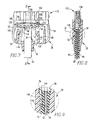
- this tongue 144 is interposed between the cable 78 and the lower interior inclined surface 56 of the housing in contacting relation with both the lower surface of the housing and the cable. (although not shown with cable 60, it will be understood that the same arrangement is used with that cable.) It will also be seen that the barbs 146 and 148 grip the insulative layer of the cable to affect a secondary strain relief function. Referring particularly to Figs. 2 - 6 it will be seen that the terminal block also includes latch guide grooves 150 and 152 for receiving, respectively, latches 52 and 54.
- a method for assembling the cable connector of the present is illustrated.
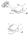
- Figs. 10a - 10d the assembly of the cable type A embodiment is illustrated.
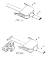
- the assembly of the cable type B is illustrated in Figs. 11a - 11d. Except for this difference, however, the two embodiments of this method are essentially identical.
- Figs. 10a and 11b in the first step of this method the concave housing 28 is slid over either the cable type A 60 (Fig. 10a) or the cable type B 78 (Fig. 1la).
- Figs. 10b and 11b the second step of the method is illustrated in which the cable is stripped and its wires are spread to form transverse extensions 70 and 74 (Fig. 10b) or transverse extensions 70, 74, 76 and 78 (Fig. 11b).
- Fig. 10c the third step in assembling the cable type A embodiment is shown in which the transverse extensions 70 and 74 are positioned in the transverse grooves 122 and 126 of projections 114 and 118.
- solder tails 72 and 76 are also connected to the contacts 130 and 132.
- Fig. 11c the third step in assembling the cable type B embodiment is shown in which the transverse extensions 70, 74, 96 and 98 are positioned in the grooves 122, 124, 126 and 128 and the solder tails 72 and 100 are connected to contact 130 while solder tail 76 and 102 are connected to contact 132.
- the final step of this method is illustrated in Figs. 10d and 11d in which it is shown that the lateral latches 52 and 54 on the housing are squeezed inwardly so as to allow them to slide in the pre-load guides of the terminal block.
- This action causes the housing to slide over the terminal block and causes the terminal block projections 114 and 118 to engage the interior walls 40 and 42 in the way shown in Fig. 7. This action also causes the tongue 114 to engage the cable as at 78 and the lower interior inclined surface 56 in the way shown in Figs. 8 and 9.
- a cable connector has been provided which reduces the number of components, integrating the function of strain relief into the terminal block, and providing a secondary strain relief which is actuated by the cover during the assembly process.
Landscapes
- Details Of Connecting Devices For Male And Female Coupling (AREA)
Claims (13)
- Connecteur de câble comprenant :chaque saillie serre-câble (114, 118) étant munie d'une portion latérale (116, 120) pour l'engagement avec les parois axiales internes (40, 44) et d'une gorge(122, 126) qui reçoit une section transversale (70, 74) du câble,(a) un logement concave (28) comprenant des faces planes opposées (30, 32) et une paroi externe (34) s'étendant perpendiculairement entre les faces planes (30, 32) et ayant une ouverture proximale (36) et une ouverture distale (38) et des première et deuxième parois axiales internes (40, 44);(b) un câble (60) s'étendant à travers l'ouverture proximale (36) dans la paroi externe (34) du logement concave (28) en direction de l'ouverture distale (38) et divergeant dans un plan adjacent à l'ouverture distale (38) du logement (28) en formant des première et deuxième sections de câble transversales opposées (70, 74) ; et(c) un bloc terminal (112) monté dans l'ouverture distale du logement (28) ayant des première et deuxième saillies serre-câbles (114, 118), chacune desdites saillies engageant l'une des parois internes axiales (40, 44) du logement (28) et l'une des sections de câble (70, 74),
caractérisé en ce que
une languette (144) s'étend du bloc terminal (112) dans un plan médian entre ladite première et deuxième saillie (114, 118) et est intercalée entre le câble (60, 78) et une surface interne inclinée (56) du logement en relation de prise avec ledit câble (60, 78), où ladite surface interne inclinée (56) est inclinée vers le bas en direction de l'ouverture distale (38) et est située sur l'une des faces planes (30, 32) du logement (28) et la languette (144) porte sur ladite surface interne inclinée (56). - Connecteur de câble selon la revendication 1, caractérisé en ce que les premier et deuxième contacts métalliques (130, 132) s'étendent à partir du bloc terminal (112) et lesdits premier et deuxième contacts métalliques (130, 132) sont connectés électriquement respectivement aux première et deuxième sections de câble transversales (70, 74).
- Connecteur de câble de la revendication 2, caractérisé en ce que le bloc terminal (112) possède au moins une ouverture distale (134) de manière à permettre un accès à au moins l'un des contacts métalliques (130, 132).
- Assemblage de connecteur de câble selon la revendication 1, caractérisé en ce que l'ouverture distale (134) est allongée transversalement.
- Assemblage de connecteur de câble selon la revendication 1, caractérisé en ce que la première paroi interne (40) possède une saillie latérale terminale (42) s'engageant dans une saillie latérale terminale (116) sur la première saillie (114) du bloc terminal (112) et la première section de câble transversale (70 ; 96, 98) est engagée dans ladite première saillie (114).
- Assemblage de connecteur de câble selon la revendication 4, caractérisé en ce que la deuxième paroi interne (44) possède une saillie latérale terminale (46) qui s'engage dans une saillie latérale terminale (120) sur la deuxième saillie (118) du bloc terminal (112) et la deuxième section de câble transversale (74 ; 104, 106) est engagée dans ladite deuxième saillie (118).
- Assemblage de connecteur de câble selon la revendication 1, caractérisé en ce que la languette (56) possède au moins un picot (146, 148) qui ancre le câble (60).
- Assemblage de connecteur de câble selon la revendication 4, caractérisé en ce que les saillies du bloc terminal (112) engagent chacune une pluralité de sections de câble transversales (70, 72).
- Assemblage de connecteur de câble selon la revendication 1, caractérisé en ce que les moyens de verrouillage latéraux opposés (52, 54) fixent le bloc terminal (112) sur le logement concave (28).
- Connecteur de câble selon les revendications 1 à 9, où le bloc terminal (112) possède une saillie généralement axiale et est monté dans l'ouverture distale (38) du logement concave (28) de telle manière que la saillie serre-câble engage le moyen de rétention du bloc interne et la section de câble transversale (70, 72).
- Connecteur de câble selon la revendication 10, caractérisé en ce qu'il existe au moins un contact métallique (130, 132) et ledit contact (130, 132) est connecté électriquement à la section de câble transversale (70, 72).
- Connecteur de câble selon la revendication 11, caractérisé en ce qu'il existe une paire de saillies serre-câbles (40, 44), espacées et parallèles qui s'étendent dans le logement (28) qui est à fixer dans les moyens d'engagement du bloc terminal interne (116, 118).
- Méthode pour l'assemblage d'un connecteur de câble selon l'une des revendications précédentes, comprenant les étapes consistant à :le bloc terminal (112) ayant une languette (144) qui engage le câble (60) en étant intercalée entre le câble (60, 70) et une surface interne inclinée (56) du logement.(a) positionner le câble (60) par rapport au logement concave (28) ayant une ouverture proximale (36) et une ouverture distale (38) et un moyen d'engagement du bloc terminal (40, 44) et de telle manière que le câble (60) passe à travers lesdites ouvertures proximale et distale (36, 38) ;(b) diviser ledit câble (60) adjacent à l'ouverture distale (38) du logement (28) pour former une paire de sections de câble transversale opposées (70, 72) ;(c) positionner un bloc terminal (112) ayant au moins une saillie axiale adjacente à l'ouverture distale du logement et engageant au moins l'une desdites sections de câble avec la saillie du bloc terminal (112); et(d) provoquer l'engagement de la saillie du bloc terminal (114, 118) avec le moyen d'engagement du bloc terminal (40, 44) dans le logement concave (28),
Applications Claiming Priority (3)
| Application Number | Priority Date | Filing Date | Title |
|---|---|---|---|
| US3131297P | 1997-01-30 | 1997-01-30 | |
| US313121 | 1997-01-30 | ||
| PCT/US1998/001874 WO1998034302A1 (fr) | 1997-01-30 | 1998-01-30 | Connecteur de cable |
Publications (3)
| Publication Number | Publication Date |
|---|---|
| EP1012920A1 EP1012920A1 (fr) | 2000-06-28 |
| EP1012920A4 EP1012920A4 (fr) | 2000-09-20 |
| EP1012920B1 true EP1012920B1 (fr) | 2003-04-16 |
Family
ID=21858753
Family Applications (1)
| Application Number | Title | Priority Date | Filing Date |
|---|---|---|---|
| EP98906070A Expired - Lifetime EP1012920B1 (fr) | 1997-01-30 | 1998-01-30 | Connecteur de cable |
Country Status (5)
| Country | Link |
|---|---|
| US (1) | US6302724B1 (fr) |
| EP (1) | EP1012920B1 (fr) |
| JP (1) | JP2001509948A (fr) |
| TW (1) | TW435857U (fr) |
| WO (1) | WO1998034302A1 (fr) |
Families Citing this family (9)
| Publication number | Priority date | Publication date | Assignee | Title |
|---|---|---|---|---|
| FR2815781B1 (fr) * | 2000-10-20 | 2005-03-11 | Arnould App Electr | Prise de courants faibles du type "prise (jack) modulaire" a moyens de connexion rapide de fils electriques |
| US6811441B2 (en) * | 2002-05-10 | 2004-11-02 | Fci Americas Technology, Inc. | Electrical cable strain relief and electrical closure |
| US7179117B2 (en) * | 2005-04-28 | 2007-02-20 | Hon Hai Precision Ind. Co., Ltd | Cable assembly with unique strain relief means |
| FR2899028B1 (fr) * | 2006-03-24 | 2009-06-05 | Schneider Electric Ind Sas | Connecteur basse tension |
| US7689089B2 (en) * | 2006-10-11 | 2010-03-30 | Panduit Corp. | Release latch for pre-terminated cassette |
| US7722382B2 (en) * | 2006-11-02 | 2010-05-25 | Tyco Electronics Corporation | Wire retention connector system |
| JP5115408B2 (ja) * | 2008-09-04 | 2013-01-09 | 住友電装株式会社 | コネクタカバー |
| US9106008B2 (en) * | 2011-11-09 | 2015-08-11 | Fuji Electric Wire Industries Co., Ltd. | Electric line wiring structure of plug |
| CN103515761B (zh) * | 2012-06-19 | 2015-11-25 | 凡甲电子(苏州)有限公司 | 电连接器组件 |
Family Cites Families (10)
| Publication number | Priority date | Publication date | Assignee | Title |
|---|---|---|---|---|
| US1731274A (en) * | 1924-06-02 | 1929-10-15 | Electric Safety Razor Corp Of | Electric cord connecter |
| US2027853A (en) * | 1934-05-19 | 1936-01-14 | Monowatt Electric Corp | Plug connecter |
| GB528195A (en) * | 1939-04-22 | 1940-10-24 | Charles Reginald Cook | Improvements in or relating to electrical lead wires and their attachment to coupling plugs or other devices |
| US2713669A (en) * | 1953-03-16 | 1955-07-19 | Cahn Herbert | Plug connector |
| DE2458254A1 (de) * | 1974-12-10 | 1976-06-16 | Insta Elektro Gmbh & Co Kg | Elektrische steckvorrichtung |
| FR2449343A1 (fr) * | 1979-02-16 | 1980-09-12 | Inovac Sa | Support de contacts, notamment pour appareil electrique a montage en bout de fil |
| US4412714A (en) * | 1980-06-13 | 1983-11-01 | Morningstar Leroy J | Latching connector assembly |
| NL8501533A (nl) * | 1985-05-29 | 1986-12-16 | Geosource Inc | Connector met naar keuze te maken interne electrische verbindingen. |
| USH113H (en) * | 1986-01-27 | 1986-08-05 | Waterblock and strain relief for electrical connectors | |
| US5336114A (en) * | 1993-05-21 | 1994-08-09 | Wang Ming Y | Copper blade securing structure of tail female receptacles |
-
1998
- 1998-01-30 WO PCT/US1998/001874 patent/WO1998034302A1/fr not_active Ceased
- 1998-01-30 JP JP53313998A patent/JP2001509948A/ja not_active Ceased
- 1998-01-30 US US09/355,472 patent/US6302724B1/en not_active Expired - Fee Related
- 1998-01-30 EP EP98906070A patent/EP1012920B1/fr not_active Expired - Lifetime
- 1998-02-16 TW TW087202171U patent/TW435857U/zh not_active IP Right Cessation
Also Published As
| Publication number | Publication date |
|---|---|
| EP1012920A4 (fr) | 2000-09-20 |
| JP2001509948A (ja) | 2001-07-24 |
| TW435857U (en) | 2001-05-16 |
| US6302724B1 (en) | 2001-10-16 |
| WO1998034302A1 (fr) | 1998-08-06 |
| EP1012920A1 (fr) | 2000-06-28 |
Similar Documents
| Publication | Publication Date | Title |
|---|---|---|
| EP0907221B1 (fr) | Connecteur pour câbles électriques | |
| US4653825A (en) | Shielded electrical connector assembly | |
| EP1003250B1 (fr) | Un connecteur blindé, un jeu de connecteurs blindés et procédé pour connecter un connecteur blindé avec un câble blindé | |
| EP0154414B1 (fr) | Adaptateur de câble rond pour fiche modulaire | |
| US4508415A (en) | Shielded electrical connector for flat cable | |
| JP3775557B2 (ja) | コネクタ | |
| EP0828315B1 (fr) | Connecteur électrique pour câble, assemblage et méthode relative | |
| US20030013341A1 (en) | Electrical connection system | |
| EP0239422A1 (fr) | Connecteur électrique pour câble plat flexible | |
| US6068505A (en) | Electrical contact for flexible flat cable | |
| US4921442A (en) | Housing for flat power cable connector | |
| EP0292528A1 (fr) | Connecteur electrique blinde pourvu d'un couvercle isolant sur l'organe de blindage | |
| EP1160930A1 (fr) | Dispositif de fixation pour un contact à fiche étanche | |
| JP2836463B2 (ja) | 圧接ジョイントコネクタ | |
| US5338233A (en) | Structure for electrically connecting a terminal and a wire | |
| EP0795930B1 (fr) | Contact électrique recevant une broche avec une force de contact élevée | |
| US4444450A (en) | Flat transmission cable connector and housing therefor | |
| US6302724B1 (en) | Cable connector having strain relief | |
| US4089579A (en) | Ribbon connector constructions | |
| EP0125760A1 (fr) | Connecteur à broches ayant une enveloppe blindée | |
| US6761576B1 (en) | Insulation displacement contact connector | |
| US5653609A (en) | Strain relief for an electrical connector | |
| US6483035B2 (en) | Protecting configuration for flat cables | |
| US6247961B1 (en) | Distribution wiring harness assembly | |
| JPH0822870A (ja) | フラットケーブルの端末防水構造 |
Legal Events
| Date | Code | Title | Description |
|---|---|---|---|
| PUAI | Public reference made under article 153(3) epc to a published international application that has entered the european phase |
Free format text: ORIGINAL CODE: 0009012 |
|
| 17P | Request for examination filed |
Effective date: 19990819 |
|
| AK | Designated contracting states |
Kind code of ref document: A1 Designated state(s): BE CH DE DK ES FI FR GB IE IT LI NL SE |
|
| A4 | Supplementary search report drawn up and despatched |
Effective date: 20000803 |
|
| AK | Designated contracting states |
Kind code of ref document: A4 Designated state(s): BE CH DE DK ES FI FR GB IE IT LI NL SE |
|
| RIC1 | Information provided on ipc code assigned before grant |
Free format text: 7H 01R 13/58 A, 7H 01R 43/20 B |
|
| 17Q | First examination report despatched |
Effective date: 20010221 |
|
| GRAG | Despatch of communication of intention to grant |
Free format text: ORIGINAL CODE: EPIDOS AGRA |
|
| GRAG | Despatch of communication of intention to grant |
Free format text: ORIGINAL CODE: EPIDOS AGRA |
|
| GRAH | Despatch of communication of intention to grant a patent |
Free format text: ORIGINAL CODE: EPIDOS IGRA |
|
| RAP1 | Party data changed (applicant data changed or rights of an application transferred) |
Owner name: FCI |
|
| GRAH | Despatch of communication of intention to grant a patent |
Free format text: ORIGINAL CODE: EPIDOS IGRA |
|
| GRAA | (expected) grant |
Free format text: ORIGINAL CODE: 0009210 |
|
| AK | Designated contracting states |
Designated state(s): BE CH DE DK ES FI FR GB IE IT LI NL SE |
|
| PG25 | Lapsed in a contracting state [announced via postgrant information from national office to epo] |
Ref country code: NL Free format text: LAPSE BECAUSE OF FAILURE TO SUBMIT A TRANSLATION OF THE DESCRIPTION OR TO PAY THE FEE WITHIN THE PRESCRIBED TIME-LIMIT Effective date: 20030416 Ref country code: LI Free format text: LAPSE BECAUSE OF FAILURE TO SUBMIT A TRANSLATION OF THE DESCRIPTION OR TO PAY THE FEE WITHIN THE PRESCRIBED TIME-LIMIT Effective date: 20030416 Ref country code: IT Free format text: LAPSE BECAUSE OF FAILURE TO SUBMIT A TRANSLATION OF THE DESCRIPTION OR TO PAY THE FEE WITHIN THE PRESCRIBED TIME-LIMIT;WARNING: LAPSES OF ITALIAN PATENTS WITH EFFECTIVE DATE BEFORE 2007 MAY HAVE OCCURRED AT ANY TIME BEFORE 2007. THE CORRECT EFFECTIVE DATE MAY BE DIFFERENT FROM THE ONE RECORDED. Effective date: 20030416 Ref country code: FI Free format text: LAPSE BECAUSE OF FAILURE TO SUBMIT A TRANSLATION OF THE DESCRIPTION OR TO PAY THE FEE WITHIN THE PRESCRIBED TIME-LIMIT Effective date: 20030416 Ref country code: CH Free format text: LAPSE BECAUSE OF FAILURE TO SUBMIT A TRANSLATION OF THE DESCRIPTION OR TO PAY THE FEE WITHIN THE PRESCRIBED TIME-LIMIT Effective date: 20030416 Ref country code: BE Free format text: LAPSE BECAUSE OF FAILURE TO SUBMIT A TRANSLATION OF THE DESCRIPTION OR TO PAY THE FEE WITHIN THE PRESCRIBED TIME-LIMIT Effective date: 20030416 |
|
| REG | Reference to a national code |
Ref country code: GB Ref legal event code: FG4D |
|
| REG | Reference to a national code |
Ref country code: CH Ref legal event code: EP |
|
| REF | Corresponds to: |
Ref document number: 69813583 Country of ref document: DE Date of ref document: 20030522 Kind code of ref document: P |
|
| REG | Reference to a national code |
Ref country code: IE Ref legal event code: FG4D |
|
| PG25 | Lapsed in a contracting state [announced via postgrant information from national office to epo] |
Ref country code: SE Free format text: LAPSE BECAUSE OF FAILURE TO SUBMIT A TRANSLATION OF THE DESCRIPTION OR TO PAY THE FEE WITHIN THE PRESCRIBED TIME-LIMIT Effective date: 20030716 Ref country code: DK Free format text: LAPSE BECAUSE OF FAILURE TO SUBMIT A TRANSLATION OF THE DESCRIPTION OR TO PAY THE FEE WITHIN THE PRESCRIBED TIME-LIMIT Effective date: 20030716 |
|
| NLV1 | Nl: lapsed or annulled due to failure to fulfill the requirements of art. 29p and 29m of the patents act | ||
| ET | Fr: translation filed | ||
| PG25 | Lapsed in a contracting state [announced via postgrant information from national office to epo] |
Ref country code: ES Free format text: LAPSE BECAUSE OF FAILURE TO SUBMIT A TRANSLATION OF THE DESCRIPTION OR TO PAY THE FEE WITHIN THE PRESCRIBED TIME-LIMIT Effective date: 20031030 |
|
| REG | Reference to a national code |
Ref country code: CH Ref legal event code: PL |
|
| PG25 | Lapsed in a contracting state [announced via postgrant information from national office to epo] |
Ref country code: IE Free format text: LAPSE BECAUSE OF NON-PAYMENT OF DUE FEES Effective date: 20040130 Ref country code: GB Free format text: LAPSE BECAUSE OF NON-PAYMENT OF DUE FEES Effective date: 20040130 |
|
| PLBE | No opposition filed within time limit |
Free format text: ORIGINAL CODE: 0009261 |
|
| STAA | Information on the status of an ep patent application or granted ep patent |
Free format text: STATUS: NO OPPOSITION FILED WITHIN TIME LIMIT |
|
| 26N | No opposition filed |
Effective date: 20040119 |
|
| GBPC | Gb: european patent ceased through non-payment of renewal fee |
Effective date: 20040130 |
|
| PG25 | Lapsed in a contracting state [announced via postgrant information from national office to epo] |
Ref country code: FR Free format text: LAPSE BECAUSE OF NON-PAYMENT OF DUE FEES Effective date: 20040930 |
|
| REG | Reference to a national code |
Ref country code: FR Ref legal event code: ST |
|
| REG | Reference to a national code |
Ref country code: IE Ref legal event code: MM4A |
|
| PGFP | Annual fee paid to national office [announced via postgrant information from national office to epo] |
Ref country code: DE Payment date: 20070131 Year of fee payment: 10 |
|
| PG25 | Lapsed in a contracting state [announced via postgrant information from national office to epo] |
Ref country code: DE Free format text: LAPSE BECAUSE OF NON-PAYMENT OF DUE FEES Effective date: 20080801 |