EP1013111B1 - Procede de liberation de connexions de telecommunications sans fil dans des systemes de telecommunications sans fil, notamment des systemes dect - Google Patents
Procede de liberation de connexions de telecommunications sans fil dans des systemes de telecommunications sans fil, notamment des systemes dect Download PDFInfo
- Publication number
- EP1013111B1 EP1013111B1 EP98948808A EP98948808A EP1013111B1 EP 1013111 B1 EP1013111 B1 EP 1013111B1 EP 98948808 A EP98948808 A EP 98948808A EP 98948808 A EP98948808 A EP 98948808A EP 1013111 B1 EP1013111 B1 EP 1013111B1
- Authority
- EP
- European Patent Office
- Prior art keywords
- telecommunication
- dips
- dect
- rpp
- iwu2
- Prior art date
- Legal status (The legal status is an assumption and is not a legal conclusion. Google has not performed a legal analysis and makes no representation as to the accuracy of the status listed.)
- Expired - Lifetime
Links
- 238000000034 method Methods 0.000 title claims abstract description 39
- 238000013270 controlled release Methods 0.000 title claims abstract 3
- 238000011017 operating method Methods 0.000 claims description 31
- 102100040834 FXYD domain-containing ion transport regulator 5 Human genes 0.000 claims 9
- 101100391551 Homo sapiens FXYD5 gene Proteins 0.000 claims 9
- 230000000712 assembly Effects 0.000 claims 2
- 238000000429 assembly Methods 0.000 claims 2
- 230000011664 signaling Effects 0.000 claims 2
- 238000012790 confirmation Methods 0.000 claims 1
- 238000012544 monitoring process Methods 0.000 claims 1
- 230000005540 biological transmission Effects 0.000 description 21
- 238000004891 communication Methods 0.000 description 7
- 238000010586 diagram Methods 0.000 description 6
- 238000012545 processing Methods 0.000 description 6
- 230000001413 cellular effect Effects 0.000 description 3
- 230000006870 function Effects 0.000 description 3
- 102100038871 SH3 and PX domain-containing protein 2B Human genes 0.000 description 2
- 101150102143 SH3PXD2B gene Proteins 0.000 description 2
- 238000005516 engineering process Methods 0.000 description 2
- 230000002028 premature Effects 0.000 description 2
- 238000012546 transfer Methods 0.000 description 2
- 101100293275 Arabidopsis thaliana NAA25 gene Proteins 0.000 description 1
- 101000760663 Hololena curta Mu-agatoxin-Hc1a Proteins 0.000 description 1
- 206010000210 abortion Diseases 0.000 description 1
- 238000009825 accumulation Methods 0.000 description 1
- 239000008186 active pharmaceutical agent Substances 0.000 description 1
- 239000002775 capsule Substances 0.000 description 1
- 238000010276 construction Methods 0.000 description 1
- 238000011161 development Methods 0.000 description 1
- 230000018109 developmental process Effects 0.000 description 1
- 230000000694 effects Effects 0.000 description 1
- 238000009434 installation Methods 0.000 description 1
- 230000010354 integration Effects 0.000 description 1
- 238000010295 mobile communication Methods 0.000 description 1
- 238000012552 review Methods 0.000 description 1
Images


Classifications
-
- H—ELECTRICITY
- H04—ELECTRIC COMMUNICATION TECHNIQUE
- H04W—WIRELESS COMMUNICATION NETWORKS
- H04W84/00—Network topologies
- H04W84/02—Hierarchically pre-organised networks, e.g. paging networks, cellular networks, WLAN [Wireless Local Area Network] or WLL [Wireless Local Loop]
- H04W84/10—Small scale networks; Flat hierarchical networks
- H04W84/14—WLL [Wireless Local Loop]; RLL [Radio Local Loop]
-
- H—ELECTRICITY
- H04—ELECTRIC COMMUNICATION TECHNIQUE
- H04M—TELEPHONIC COMMUNICATION
- H04M1/00—Substation equipment, e.g. for use by subscribers
- H04M1/72—Mobile telephones; Cordless telephones, i.e. devices for establishing wireless links to base stations without route selection
- H04M1/725—Cordless telephones
- H04M1/72502—Cordless telephones with one base station connected to a single line
- H04M1/72505—Radio link set-up procedures
-
- H—ELECTRICITY
- H04—ELECTRIC COMMUNICATION TECHNIQUE
- H04M—TELEPHONIC COMMUNICATION
- H04M2250/00—Details of telephonic subscriber devices
- H04M2250/08—Details of telephonic subscriber devices home cordless telephone systems using the DECT standard
Definitions
- the transmission type according to (1) ... (3) is normal characterized by continuous (analog) signals, while usually discontinuous for the type of transmission according to (4) Signals (e.g. impulses, digital signals) arise.
- Signals e.g. impulses, digital signals
- the invention relates to a method for user controlled dismantling of wireless telecommunication connections in wireless telecommunication systems, especially DECT systems
- Telecommunication systems of the type defined above are, for example, DECT systems [Digital Enhanced (formerly: European) Cordless Telecommunication; see. (1): Communications Engineering Electronics 42 (1992) January / February No. 1, Berlin, DE; U. Pil ger "Structure of the DECT standard", pages 23 to 29 in connection with the ETSI publication ETS 300175-1 ... 9, October 1992; (2): Telcom Report 16 (1993), No. 1, JH Koch: "Digital convenience for cordless telecommunications - DECT standard opens up new areas of use", pages 26 and 27; (3): tec 2/93 - Ascom's technical magazine “Paths to universal mobile telecommunications", pages 35 to 42; (4) : Philips Telecommunicatian Review, Vol. 49, No. 3, Sept.
- a maximum of 12 connections according to TDMA / FDMA can be established at a DECT / GAP base station BS via a DECT / GAP air interface designed for the frequency range between 1.88 and 1.90 GHz, as shown in FIG. 1 / TDD procedure ( T ime D ivision M ultiple A ccess / F requency D ivision M ultiple A ccess / T ime D ivision D uplex) can be set up parallel to DECT / GAP handsets MT1 ... MT12.
- the connections can be internal and / or external.
- two mobile parts registered at the base station BS for example the mobile part MT2 and the mobile part MT3, can communicate with one another.
- the base station BS is connected to a telecommunications network TKN, for example in a line-bound form via a telecommunications connection unit TAE or a private branch exchange NStA with a line-bound telecommunications network or in accordance with WO 95/05040 in a wireless form as a repeater station with a higher-level telecommunications network ,
- a mobile part for example with the mobile part MT1
- the base station BS the telecommunication connection unit TAE or private branch exchange NStA with a subscriber in the telecommunication network TKN.
- a second handset for example the MT12 handset, uses the second connection for an external connection instead of the TKE telecommunication terminal.
- the mobile parts MT1 ... MT12 are operated with a battery or an accumulator
- the base station BS which is designed as a cordless small switching system, is connected to a voltage network SPN via a network connection device NAG.
- FIGURE 2 shows, starting from the publication Components 31 (1993), issue 6, pages 215 to 218; S. Althammer, D. Brückmann: "Highly optimized IC's for DECT cordless phones" the basic circuit structure of the base station BS and the handset MT.
- the base station BS and the mobile part MT then have a radio part FKT with an antenna ANT assigned for transmitting and receiving radio signals, a signal processing device SVE and a central control ZST, which are connected to one another in the manner shown.
- the radio part FKT essentially contains the known devices such as transmitter SE, receiver EM and synthesizer SYN.
- a coding / decoding device CODEC is included in the signal processing device SVE.
- the central control ZST has a microprocessor ⁇ P for the base station BS as well as for the mobile part MT with an OSI / ISO layer model [ cf. (1) : Struktursver - Irish Mathematics, vol. 48, 2/1995, pages 102 to 111; (2) : ETSI publication ETS 300175-1 ... 9, October 1992 ] built program module PGM, a signal control part SST and a digital signal processor DSP, which are interconnected in the manner shown. Of the layers defined in the layer model, only the first four layers that are essential for the base station BS and the mobile part MT are shown.
- the signal control part SST is designed in the base station BS as a time switch controller TSC and in the mobile part MT as a burst mode controller BMC.
- the main difference between the two signal control parts TSC, BMC is that the base station-specific signal control part TSC takes on additional switching functions (switch functions) compared to the mobile part-specific signal control part BMC.
- FIGURE 2 The circuit structure described in FIGURE 2 is used in the Base station BS and the handset MT according to their function in the DECT / GAP system according to FIGURE 1 by additional functional units added.
- the base station BS is via the signal processing device SVE and the telecommunication connection unit TAE or the private branch exchange with the telecommunications network TKN connected.
- the base station BS can have one Have user interface (dashed lines in FIGURE 2 Functional units) which e.g. from one as a keyboard trained input device EE, one as a display trained display device AE, one as a handset Speech / hearing device designed with MIF microphone and HK hearing capsule SHE and a TRK ringer.
- the mobile part MT has the option at the base station BS Possible user interface with the associated user interface belonging to the controls described above.
- FIGURE 3 shows, starting from the DECT system according to FIGURE 1, a cellular DECT / GAP multisystem CMI ( C ordless M ulticell I ntegration), in which several of the DECT / GAP systems TKS described above, each with a base station BS and one / several Handset (s) MT at any geographical location, for example in an administration building with large floor offices, concentrated - in the sense of a "hot spot" arrangement.
- CMI C ordless M ulticell I ntegration
- a "closed" geographical location like the administration building
- there is also an "open" geographical location with strategic telecommunication meaning for example places in big cities with a high traffic volume, a large accumulation of commercial units and a 'big movement of people' for the installation of a cellular DECT / GAP multisystem CMI possible.
- some of the base stations BS arranged in the open-plan office are designed as antenna diversity base stations in accordance with WO 94/10764.
- the concentration of the DECT / GAP systems TKS is so pronounced (complete radio coverage of the geographical location) that individual DECT / GAP systems TKS work in the same environment due to the overlapping cellular DECT / GAP radio areas FB.
- FIGS. 1 to 3 The cordless telecommunications scenario shown in FIGS. 1 to 3, in which DECT handsets are connected via a DECT air interface to a private (residential) DECT base station (FIGURE 1) or to one or more private or public (public) DECT Base stations (FIGURE 3) can now be connected, according to the publication "Lecture by A. Elberse, M. Barry, G. Fleming on the topic:” DECT Da ta Services - DECT in Fixed and Mobile Networks ", 17th / 18th June 1996, Hotel Sofitel, Paris; pages 1 to 12 and summary " so that the DECT handsets can be connected to private and public DECT base stations via the DECT air interface.
- FIGURE 4 shows - starting from the publications " Karlunikationstechnik Electronics, Berlin 45, (1995), Issue 1, Pages 21 to 23 and Issue 3, Pages 29 and 30" and IEE Colloquium 1993, 173; (1993), pp. 29/1 - 29/7 ; W.
- the DECT telecommunications subsystem D-TTS can - how will be explained in more detail below - part of a DECT / ISDN Intermediate Systems DIIS or an RLL / WLL telecommunications subsystem Be RW-TTS.
- the DECT telecommunications subsystem D-TTS and thus the DECT / ISDN Intermediate system DIIS or the RLL / WLL telecommunications subsystem RW-TTS are preferably based on a DECT / GAP system DGS as shown for example in FIGURE 1 is.
- the DECT / ISDN Intermediate System DIIS or the RLL / WLL telecommunications subsystem RW-TTS can alternatively also be based on a GSM system ( G roupe S fugciale M obile or G lobal S ystem for M obile Communication; cf. 1991) June, No. 3, Berlin, DE; A.Mann: "The GSM standard - basis for digital European mobile radio networks", pages 137 to 152).
- GSM G roupe S fuge M obile or G lobal S ystem for M obile Communication; cf. 1991
- GSM G roupe S fuge M obile or G lobal S ystem for M obile Communication
- A.Mann "The GSM standard - basis for digital European mobile radio networks", pages 137 to 152).
- the ISDN telecommunication subsystem I-TTS as a GSM-system or as a PSTN system (P ublic S witched T elecommunications
- radio channels e.g. DECT channels
- ISDN analog to digital network
- the wireless connection technology RLL / WLL R adio in the L ocal Loop / W ireless in the L ocal L oop
- the ISDN subscriber ISDN - Services are made available on standard ISDN interfaces (see FIGURE 4).
- the DECT / ISDN Intermediate System DIIS which is designed as a local message transmission loop and is preferably DECT-specific and is contained in the RLL / WLL telecommunications subsystem RW-TTS, a further standardized S-interface (S-BUS ), a network termination NT (N etwork T ermination) and a standardized U interface of the ISDN telecommunication sub-system I-TTS and, secondly, a second telecommunications subscriber TCU2 as end-users of the DECT / ISDN intermediate system DIIS in the ISDN world and their available services involved.
- S-BUS a standardized S-interface
- the DECT / ISDN intermediate system DIIS consists essentially of two telecommunications interfaces, a first telecommunications interface DIFS (D ECT I ntermediate F ixed S ystem) and a second telecommunications interface DIPS (D E CT I ntermediate P ortable S ystem) that wirelessly, for example via a DECT air interface. Because of the quasi-localized first telecommunication interface DIFS, the DECT / ISDN Intermediate System DIIS forms the local message transmission loop defined above in this context.
- the first telecommunication interface DIFS a radio fixed part RFP (R adio F ixed P art), an interworking unit IWU 1 (I nter W orking U nit) and an interface circuit INC1 (I nterface C ircuitry) to the S-interface.
- the second telecommunication interface DIPS contains a radio portable part RPP (R adio P ortable P art) and an interworking unit IWU 2 (I nter W orking U nit) and, optionally, an interface circuit INC2 (IN terface C ircuitry) to the S-interface.
- the RFP fixed part and the RPP radio handset form the well-known DECT / GAP system DGS.
- FIG. 4 shows - as already mentioned - on the one hand (1st possibility) as a typical RLL / WLL scenario like the DECT / ISDN Intermediate System DIIS within the RLL / WLL telecommunications subsystem RW-TTS in the ISDN telecommunications subsystem I- TTS is included as a local message transmission loop and on the other (option 2) as the DECT / ISDN intermediate system DIIS under CAP-points (C ordless terminal Mobility A ccess P rofile) is only on the network side connected to the ISDN telecommunication subsystem I-TTS.
- the interface circuit INC2 of the second telecommunication interface DIPS to the S interface is not active or is not available at all.
- the interface circuit INC2 of the second telecommunication interface DIPS is shown in dashed lines in order to graphically represent and substantiate this situation as a whole. While the second telecommunication interface DIPS in the first option is not, for example, designed for a specific handset, ie with a user interface, the second telecommunication interface DIPS in the second option is designed as a typical mobile part with a user interface.
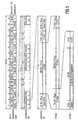
- FIGURE 5 shows, based on the publication "communications engineering Elektronik 42 (1992) Jan./Feb., No. 1, Berlin, DE; U. Pilger: "Structure of the DECT standard", pages 23 to 29 in Connection with ETS 300 175-1 ... October 9, 1992 "the TDMA structure of the DECT / GAP system DGS.
- the DECT / GAP system is a hybrid system with regard to multiple access methods, in accordance with the FDMA principle on ten frequencies in the frequency band between 1.88 and 1.9 GHz radio messages after the TDMA principle according to FIG 5 in a predetermined time Sequence from the base station BS to the handset MT and from the handset MT to base station BS (time division duplex operation) can be sent.
- the chronological order is from determined a multi-time frame MZR that occurs every 160 ms and the 16 time frame ZR, each with a duration of 10 ms.
- this time frame ZR will be by base station BS and handset MT transmit information separately a C, M, N, P, Q channel defined in the DECT standard affect. Will information in a timeframe ZR If several of these channels are transmitted, the transmission takes place according to a priority list with M> C> N and P> N.
- time slots ZS time slots 12 ... 23
- time slots 12 ... 23 time slots 12 ... 23
- ZS time slots 12 ... 23
- ZS information with a bit length according to the DECT standard transferred from 480 bits.
- 32 become as synchronization information in a SYNC field and 388 Bit transmitted as useful information in a D field.
- the remaining 60 bits are used as additional information in a Z field and transmitted as protection information in a "guard time” field.
- the 388 bits of the D field transmitted as user information are subdivided into a 64-bit A field, a 320 bit long B field and a 4 bit long "X-CRC" word.
- the 64-bit A field consists of an 8-bit data header (Header), a 40-bit data record with data for the C, Q, M, N, P channels and a 16 bit long "A-CRC" word together.
- the base station BS (R adio F ixed P art RFP) according to the Figures 1 to 5 transmits over the DECT air interface at regular intervals on simplex transmission paths, the so-called dummy bearer, broadcast information from the mobile unit MT (R adio P ortable P art RPP) are received according to FIGURES 1 to 5 and serve this for the synchronization and the establishment of a connection with the base station.
- the broadcast information does not necessarily have to be sent on a dummy transmission path (dummy bearer).
- the base station already has at least one telecommunication connection, a so-called traffic transmission path (Traffic Bearer), to another handset and on which it then sends the necessary broadcast information.
- the handset MT, 'RPP which is a telecommunication connection to the base station BS, RFP would like the broadcast information - like when transmitting the Broadcast information on the dummy transmission path - received.
- connection is established by the handset MT, RPP according to the rules of channel selection (cf. ETSI publication ETS 300175-5, October 1992, chapter 9 and especially chapter 9.3), after which a new channel for establishing a new connection selected and a connection request (CC-SETUP) to the base station BS, RFP.
- CC-SETUP connection request
- connection is cleared by the handset MT, RPP in that the handset MT, RPP trigger a connection (CC-RELEASE) to the base station BS, RFP sends.
- connection setup and disconnection of the MT, RPP handset is carried out according to the DECT standard [ see: ETS 300175-5, October 1992 (first edition) or September 1996 (second edition), chap. 9 and Annex A ] are monitored by time counters (timers) so that the corresponding DECT-specific call control state machines fall back into a defined state in the event of an error (eg DECT base station BS, RFP does not respond).
- DECT standard see: ETS 300175-5, October 1992 (first edition) or September 1996 (second edition), chap. 9 and Annex A ] are monitored by time counters (timers) so that the corresponding DECT-specific call control state machines fall back into a defined state in the event of an error (eg DECT base station BS, RFP does not respond).
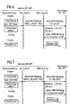
- FIGURE 6 shows the message flow diagram for the connection establishment, in which the base station BS, RFP according to one of the Handset MT, RPP to establish the connection sent first NWK message "CC-SETUP" not within a specified the first time counter provided for establishing the connection ⁇ CC-03> available time of 20 seconds to establish the connection approved. For this time of 20 seconds the connection establishment is monitored and e.g. on the display of the Handset MT, RPP displayed as such.
- RPP handset Before the MT, RPP handset receives the first NWK message "CC-SETUP" to the base station BS, RFP is sent on the user interface of the handset MT, RPP to initiate the connection as the first operating procedure, press the "OFF HOOK” button, whereupon in the handset MT, RPP according to the DECT protocol according to the ISO / OSI layer model from the IWU layer to the NWK layer transmit a first IWU message "MNCC_SETUP_REQ" becomes.
- FIGURE 7 shows the message flow diagram for the connection cleardown, in which the base station BS, RFP after one of the handset MT, RPP to clear the connection sent third NWK message "CC-RELEASE" not within one as required a second time counter provided for the clearing of the connection ⁇ CC-02> available time of 36 seconds Connection cleared confirmed. For this time of 36 seconds the disconnection is monitored and e.g. on the display of the handset MT, RPP as such.
- RPP handset Before the MT, RPP handset receives the third NWK message "CC-RELEASE” to the base station BS, RFP is sent on the user interface of the handset MT, RPP to initiate the disconnection press the "ON HOOK” key, and then on the handset MT, RPP according to the DECT protocol according to the ISO / OSI layer model from the IWU layer to the NWK layer one second IWU message "MNCC_RELEASE_REQ" is transmitted.
- FIGURE 6 For the connection establishment, it is at Siemens GSM mobile phones known to have a handset side the "OFF HOOK” button (green button) initiated connection establishment prematurely, i.e. before the countdown of the corresponding Cancel the time counter with the "ON HOOK” button (red button).
- the object underlying the invention is that user-controlled removal of wireless telecommunications connections in wireless telecommunication systems, in particular DECT systems, user-friendly and acceptable trigger.
- the idea underlying the invention is that once established connections between through wireless telecommunications connectable telecommunication devices in wireless telecommunication systems of the initially outlined Art- e.g. '. DECT handsets and DECT base stations in DECT systems - in two stages through operating procedures (second operating procedures), that differ from operating procedures (first operating procedures) differentiate for the connection establishment, absolutely dismantled or canceled.
- the unconditional dismantling or breaking of the connections between the telecommunication devices connectable by wireless telecommunication in wireless telecommunication systems can in principle be carried out regardless of whether the wireless telecommunication between the telecommunication devices is disturbed or not (normal case mentioned above).
- the method is particularly useful if the connections for dismantling and in addition both for construction and for dismantling are disturbed.
- the unconditional disconnection or the connection termination is voice-controlled (e.g. with Voice commands "disconnect” and "disconnect”) perform.
- FIGURE 9 shows starting from FIGURES 6 and 7 and in conjunction with the ETSI publication ETS 300175-5, October 1992, Cape. 9, Figures 3 and 4 and Annex B.1 a message flow diagram for an unconditional disconnection or for one Connection aborted after a previously by the first operating procedure - Press the "OFF HOOK” button according to FIGURE 6 - initiated but not yet established connection establishment, before the connection is established on the user interface (e.g. display) of the MT, RPP handset if necessary "Handset xy" appears and the CC state machine is in state T-00.
- the user interface e.g. display
- connection is established in a conventional manner user controlled by the "OFF HOOK” button as the first Operating procedure as shown in FIGURE 6 is initiated in the handset MT, RPP according to the DECT protocol according to the ISO / OSI layer model the first from the IWU layer to the NWK layer Transfer IWU message "MNCC_SETUP_REQ".
- MNCC_SETUP_REQ the NWK layer Transfer IWU message "MNCC_SETUP_REQ”.
- MNCC_SETUP_REQ the NWK level the transmission of the first NWK message "CC-SETUP" the base station BS, RFP.
- the CC state machine goes as a result of this in the CC state T-01.
- RPP if necessary preferably "Connection establishment" is displayed.
- the handset MT, RPP according to the DECT protocol according to the ISO / OSI layer model the second IWU message from the IWU layer to the NWK layer "MNCC_RELEASE_REQ" transferred.
- the first time counter ⁇ CC-03> stopped and reset or the time counting process is aborted and the time counter ⁇ CC-03> reset and the third NWK message "CC-RELEASE” is transmitted to the base station BS, RFP.
- the CC state machine as a result, goes into CC state T-19.
- RPP may be preferably "disconnect" displayed.
- connection establishment as well as the unconditional disconnection or.
- disconnection voice controlled e.g. with voice commands "connection establish “,” disconnect “and” disconnect " perform.
Landscapes
- Engineering & Computer Science (AREA)
- Computer Networks & Wireless Communication (AREA)
- Signal Processing (AREA)
- Mobile Radio Communication Systems (AREA)
Abstract
Claims (15)
- Procédé pour la coupure commandée par l'utilisateur de liaisons de télécommunication sans fil dans des systèmes de télécommunication sans fil, en particulier des systèmes DECT, dans lequel des liaisons de télécommunication sans fil sont établies entre des premiers appareils de télécommunication (MT, DIPS, RPP, IWU2, INC2, TE) et des seconds appareils de télécommunication (BS, DIFS, RFP, IWU1, INC1) des systèmes de télécommunication (TKS, DIIS, RW-TTS) par des premières procédures de commande sur des interfaces utilisateur des premiers appareils de télécommunication (MT, DIPS, RPP, IWU2, INC2, TE) et sont coupées par des secondes procédures de commande sur les interfaces utilisateur des premiers appareils de télécommunication (MT, DIPS, RPP, IWU2, INC2, TE), les premières procédures de commande déclenchant des flux de message prédéfinis signalant l'établissement de communication et les secondes procédures de commande des flux de message prédéfinis signalant la coupure de communication entre les premiers appareils de télécommunication (MT, DIPS, RPP, IWU2, INC2) et les seconds appareils de télécommunication (BS, DIPS, RFP, IWU1, INC1),
caractérisé en ce que
les liaisons de télécommunication sans fil sont coupées resp. interrompues impérativement par les secondes procédures de commande en deux étapes - sans confirmation par les seconds appareils de télécommunication (BS, DIPS, RFP, IWU1, INC1) ou avant l'expiration des compteurs de temps <CC-02> contrôlant la coupure de communication. - Procédé selon la revendication 1, caractérisé en ce que
des touches sont actionnées lors des procédures de commande. - Procédé selon la revendication 1 ou 2, caractérisé en ce que
des instructions vocales sont entrées lors des procédures de commande. - Procédé selon la revendication 2, caractérisé en ce que
des touches "OFF HOOK" sont actionnées lors des premières procédures de commande. - Procédé selon la revendication 2, caractérisé en ce que
des touches "ON HOOK" sont actionnées deux fois successivement lors des secondes procédures de commande. - Procédé selon la revendication 3, caractérisé en ce que
des premières instructions vocales "établir communication" sont entrées lors des premières procédures de commande. - Procédé selon la revendication 3, caractérisé en ce que
des secondes instructions vocales "couper communication" et des troisièmes instructions vocales "interrompre communication" sont entrées lors des secondes procédures de commande. - Procédé selon l'une quelconque des revendications 1 à 7, caractérisé en ce que
des systèmes DECT sont utilisés comme systèmes de télécommunication (TKS, DIIS, RW-TTS), les liaisons de télécommunication sont établies et interrompues resp. coupées impérativement selon le procédé de radio DECT, des parties mobiles DECT (MT, DIPS, RPP, IWU2) ou des ensembles de terminaison de réseau DECT (DIPS, RPP, IWU2, INC2) avec des terminaux (TE) attribués, reliés par fils et présentant des interfaces utilisateur sont utilisés comme premiers appareils de télécommunication (MT, DIPS, RPP, IWU2, INC2, TE) et des stations de base DECT sont utilisées comme seconds appareils de télécommunication (BS, DIPS, RFP, IWU1, INC1). - Procédé selon l'une quelconque des revendications 1 à 7, caractérisé en ce que
des systèmes GSM sont utilisés comme systèmes de télécommunication (TKS, DIIS, RW-TTS), les liaisons de télécommunication sont établies et coupées resp. interrompues impérativement selon le protocole radio GSM, des parties mobiles GSM sont utilisées comme premiers appareils de télécommunication (MT, DIPS, RPP, IWU2, INC2, TE) et des stations de base GSM avec des appareils de commutation centraux attribués sont utilisées comme seconds appareils de télécommunication (BS, DIPS, RFP, IWU1, INC1). - Procédé selon l'une quelconque des revendications 1 à 7, caractérisé en ce que
des systèmes hybrides en ce qui concerne les méthodes d'accès multiple CDMA/FDMA/TDMA sont utilisés comme systèmes de télécommunication (TKS, DIIS, RW-TTS), les liaisons de télécommunication sont établies et interrompues resp. coupées impérativement selon le protocole radio hybride prenant en compte les méthodes d'accès multiple CDMA/FDMA/TDMA, des parties mobiles à structure hybride par rapport aux méthodes d'accès multiple CDMA/FDMA/TDMA ou des ensembles de terminaison de réseau à structure hybride par rapport aux méthodes d'accès multiple CDMA/FDMA/TDMA avec des terminaux attribués, reliés par fil et présentant des interfaces utilisateur sont utilisés comme premiers appareils de télécommunication (MT, DIPS, RPP, IWU2, INC2, TE) et des stations de base à structure hybride par rapport aux méthodes d'accès multiple CDMA/FDMA/TDMA sont utilisées comme seconds appareils de télécommunication (BS, DIPS, RFP, IWU1, INC1). - Procédé selon l'une quelconque des revendications 1 à 10, caractérisé en ce que
les interruptions de liaison de télécommunication sont déclenchées par les premiers appareils de télécommunication (MT, DIPS, RPP, IWU2, INC2, TE) en cas de liaisons de télécommunication perturbées entre les premiers appareils de télécommunication (MT, DIPS, RPP, IWU2, INC2, TE) et les seconds appareils de télécommunication (BS, DIPS, RFP, IWU1, INC1). - Procédé selon l'une quelconque des revendications 1 à 11, caractérisé en ce que
les établissements de liaison de télécommunication sont déclenchés par les premiers appareils de télécommunication (MT, DIPS, RPP, IWU2, INC2, TE) en cas de liaisons de télécommunication perturbées entre les premiers appareils de télécommunication (MT, DIPS, RPP, IWU2, INC2, TE) et les seconds appareils de télécommunication (BS, DIPS, RFP, IWU1, INC1). - Procédé selon la revendication 8, caractérisé en ce que
les liaisons de télécommunication sont interrompues resp. coupées impérativement selon le protocole radio DECT par le fait que les parties mobiles DECT (MT, DIPS, RPP, IWU2) ou les ensembles de terminaison de réseau DECT (DIPS, RPP, IWU2) transmettent avec les terminaux TE attribués, reliés par fils et présentant des interfaces utilisateur, déclenchés par les secondes procédures de commande, des premiers messages NWK "CC-RELEASE" et des seconds messages "CC-RELEASE-COMplete" aux stations de base DECT (BS, DIPS, RFP, IWU1, INC1). - Procédé selon la revendication 8, 11 ou 13, caractérisé en ce que
les coupures de liaison de télécommunication sont déclenchées par les premiers messages NWK "CC-RELEASE". - Procédé selon les revendications 8 et 12, caractérisé en ce que
les établissements de liaison de télécommunication sont déclenchés par des troisièmes messages NWK "CC-SETUP".
Applications Claiming Priority (3)
| Application Number | Priority Date | Filing Date | Title |
|---|---|---|---|
| DE19738339A DE19738339C2 (de) | 1997-09-02 | 1997-09-02 | Verfahren zum benutzergesteuerten Abbauen von drahtlosen Telekommunikationsverbindungen in drahtlosen Telekommunikationssystemen, insbesondere DECT-Systemen |
| DE19738339 | 1997-09-02 | ||
| PCT/DE1998/002404 WO1999012361A1 (fr) | 1997-09-02 | 1998-08-18 | Procede d'arret pilote par l'utilisateur de communications de telecommunications sans fil dans des systemes de telecommunications sans fil, notamment des systemes dect |
Publications (2)
| Publication Number | Publication Date |
|---|---|
| EP1013111A1 EP1013111A1 (fr) | 2000-06-28 |
| EP1013111B1 true EP1013111B1 (fr) | 2004-04-07 |
Family
ID=7840969
Family Applications (1)
| Application Number | Title | Priority Date | Filing Date |
|---|---|---|---|
| EP98948808A Expired - Lifetime EP1013111B1 (fr) | 1997-09-02 | 1998-08-18 | Procede de liberation de connexions de telecommunications sans fil dans des systemes de telecommunications sans fil, notamment des systemes dect |
Country Status (10)
| Country | Link |
|---|---|
| US (1) | US6625443B1 (fr) |
| EP (1) | EP1013111B1 (fr) |
| JP (1) | JP2001515322A (fr) |
| AR (1) | AR009690A1 (fr) |
| AU (1) | AU9531098A (fr) |
| CA (1) | CA2302295A1 (fr) |
| DE (2) | DE19738339C2 (fr) |
| ES (1) | ES2219911T3 (fr) |
| WO (1) | WO1999012361A1 (fr) |
| ZA (1) | ZA987951B (fr) |
Families Citing this family (8)
| Publication number | Priority date | Publication date | Assignee | Title |
|---|---|---|---|---|
| WO1999034339A2 (fr) | 1997-12-29 | 1999-07-08 | Ameritech Corporation | Systeme de domotique et de telesecurite residentielle et procede associe |
| US7349682B1 (en) * | 1998-06-12 | 2008-03-25 | Sbc Properties, L.P. | Home gateway system for automation and security |
| DE19927585A1 (de) * | 1999-06-16 | 2000-12-28 | Siemens Ag | Basisstation für ein Schnurlostelefon |
| ITTO20010207A1 (it) * | 2001-03-08 | 2002-09-08 | Itec Srl | Rete di telecomunicazioni per utenti mobili migliorata e relativi apparati. |
| US20030208695A1 (en) * | 2002-05-01 | 2003-11-06 | Ronald Soto | Method and system for controlled, centrally authenticated remote access |
| ATE556530T1 (de) | 2007-03-16 | 2012-05-15 | Gigaset Communications Gmbh | Vorrichtung und verfahren zur steuerung des aufbaus einer nutzkanalverbindung in einem kommunikationssystem |
| DE102012100664A1 (de) * | 2012-01-26 | 2013-08-01 | Gigaset Communications Gmbh | Ereignisgesteuertes Kommunikationsgerät mit einer Einrichtung zur Erkennung von Sprachaktivität |
| US9820216B1 (en) * | 2014-05-12 | 2017-11-14 | Sprint Communications Company L.P. | Wireless traffic channel release prevention before update process completion |
Family Cites Families (19)
| Publication number | Priority date | Publication date | Assignee | Title |
|---|---|---|---|---|
| EP0307193B1 (fr) * | 1987-09-11 | 1993-11-18 | Kabushiki Kaisha Toshiba | Appareil téléphonique |
| DE4008598C2 (de) * | 1990-03-17 | 1995-08-17 | Philips Patentverwaltung | Mobilfunkgerät mit einem mindestens eine Funktionstaste aufweisenden Bedienteil |
| GB2264209B (en) * | 1992-02-06 | 1995-11-08 | Technophone Ltd | Cordless telephone arrangement |
| WO1993021719A1 (fr) * | 1992-04-09 | 1993-10-28 | Siemens Aktiengesellschaft | Procede de structuration d'un format de champ b en norme dect |
| US5297183A (en) * | 1992-04-13 | 1994-03-22 | Vcs Industries, Inc. | Speech recognition system for electronic switches in a cellular telephone or personal communication network |
| ES2085800T3 (es) * | 1992-10-26 | 1996-06-01 | Siemens Ag | Procedimiento y disposicion para la diversidad de seleccion de antenas en un sistema telefonico inalambrico. |
| SE500826C2 (sv) * | 1993-01-27 | 1994-09-12 | Ericsson Telefon Ab L M | Metod att nedkoppla en upprättad kommunikationsförbindelse i ett mobilradiosystem |
| SE517451C2 (sv) * | 1993-06-02 | 2002-06-04 | Telia Ab | Anordning vid radiosystem med kort räckvidd |
| TW365603B (en) * | 1993-07-30 | 1999-08-01 | Rhone Poulenc Rorer Sa | Novel perhydroisoindole derivatives, their preparation and pharmaceutical compositions which contain them |
| KR950704921A (ko) * | 1993-09-03 | 1995-11-20 | 타게 뢰흐그렌ㆍ얼링 블로메 | 이동국에 부가 서비스를 제공하기 위한 방법 및 장치(a method and system for providing supplementary services to a mobile station) |
| US6088590A (en) * | 1993-11-01 | 2000-07-11 | Omnipoint Corporation | Method and system for mobile controlled handoff and link maintenance in spread spectrum communication |
| DE19533541C1 (de) * | 1995-09-11 | 1997-03-27 | Daimler Benz Aerospace Ag | Verfahren zur automatischen Steuerung eines oder mehrerer Geräte durch Sprachkommandos oder per Sprachdialog im Echtzeitbetrieb und Vorrichtung zum Ausführen des Verfahrens |
| US5956635A (en) * | 1996-07-16 | 1999-09-21 | Cellular Technical Services Company, Inc. | Detection and prevention of channel grabbing in a wireless communications system |
| DE19632261C2 (de) * | 1996-08-09 | 1998-07-09 | Siemens Ag | Verfahren zum Aufbauen von Telekommunikationsverbindungen zwischen Telekommunikationsgeräten in drahtlosen Telekommunikationssystemen, insbesondere zwischen DECT-Geräten eines DECT-Systems |
| DE19643774C1 (de) * | 1996-10-23 | 1998-04-30 | Siemens Ag | Verfahren und Telekommunikationsschnittstelle zum Übertragen kontinuierlicher und/oder diskontinuierlicher Datenströme in einem hybriden Telekommunikationssystem, insbesondere einem "ISDN-DECT-spezifischen RLL/WLL"-System |
| US6438380B1 (en) * | 1997-02-28 | 2002-08-20 | Lucent Technologies Inc. | System for robust location of a mobile-transmitter |
| DE19719163A1 (de) * | 1997-05-06 | 1998-11-12 | Siemens Ag | Multifunktionales Mobilkommunikationsgerät |
| US6259906B1 (en) * | 1997-08-20 | 2001-07-10 | Telefonaktiebolaget L M Ericsson (Publ) | Apparatus and method for indicating service subscription selection in a cellular communication system |
| US6405033B1 (en) * | 1998-07-29 | 2002-06-11 | Track Communications, Inc. | System and method for routing a call using a communications network |
-
1997
- 1997-09-02 DE DE19738339A patent/DE19738339C2/de not_active Expired - Fee Related
-
1998
- 1998-08-18 CA CA002302295A patent/CA2302295A1/fr not_active Abandoned
- 1998-08-18 AU AU95310/98A patent/AU9531098A/en not_active Abandoned
- 1998-08-18 WO PCT/DE1998/002404 patent/WO1999012361A1/fr not_active Ceased
- 1998-08-18 EP EP98948808A patent/EP1013111B1/fr not_active Expired - Lifetime
- 1998-08-18 DE DE59811155T patent/DE59811155D1/de not_active Expired - Lifetime
- 1998-08-18 US US09/486,945 patent/US6625443B1/en not_active Expired - Fee Related
- 1998-08-18 ES ES98948808T patent/ES2219911T3/es not_active Expired - Lifetime
- 1998-08-18 JP JP2000509229A patent/JP2001515322A/ja active Pending
- 1998-08-24 AR ARP980104185A patent/AR009690A1/es active IP Right Grant
- 1998-09-01 ZA ZA987951A patent/ZA987951B/xx unknown
Also Published As
| Publication number | Publication date |
|---|---|
| US6625443B1 (en) | 2003-09-23 |
| AU9531098A (en) | 1999-03-22 |
| AR009690A1 (es) | 2000-04-26 |
| DE19738339C2 (de) | 2000-08-31 |
| WO1999012361A1 (fr) | 1999-03-11 |
| DE59811155D1 (de) | 2004-05-13 |
| EP1013111A1 (fr) | 2000-06-28 |
| CA2302295A1 (fr) | 1999-03-11 |
| ES2219911T3 (es) | 2004-12-01 |
| ZA987951B (en) | 1999-03-02 |
| DE19738339A1 (de) | 1999-03-04 |
| JP2001515322A (ja) | 2001-09-18 |
Similar Documents
| Publication | Publication Date | Title |
|---|---|---|
| EP0947059B1 (fr) | Procede d'etablissement de liaisons de telecommunication entre des appareils de telecommunication dans des systemes de telecommunication sans fil, en particulier entre des appareils dect d'un systeme dect | |
| EP0925697B1 (fr) | Procede pour le lancement d'appels d'urgence avec des systemes de telecommunication sans cordon, en particulier des systemes dect/gap | |
| EP0929985B1 (fr) | Station de base a fonction de transfert rapide d'un systeme radio amrt/amrf cellulaire, en particulier d'un systeme dect cellulaire | |
| EP1016305B1 (fr) | Procede pour inscrire des appareils de telecommunication dans des stations de base pouvant etre reliees auxdits appareils de telecommunication, dans des systemes de telecommunication sans fil, notamment pour inscrire des unites mobiles dect dans des stations de base dect de systemes dect | |
| EP1013111B1 (fr) | Procede de liberation de connexions de telecommunications sans fil dans des systemes de telecommunications sans fil, notamment des systemes dect | |
| EP0925696B1 (fr) | Procede de controle du lancement d'appels d'urgence avec des systemes de telecommunication sans cordon, en particulier des systemens dect/gap | |
| DE19740558C2 (de) | Verfahren zum Übertragen von "MWI-Dienst"-spezifischen Nachrichten in Telekommunikationsnetzen, insbesondere in hybriden DECT/ISDN-spezifischen Telekommunikationsnetzen | |
| EP1016293B1 (fr) | Procede pour commander des autorisations d'acces d'appareils de telecommunication dans des stations de base de systemes de telecommunication sans fil entre des appareils de telecommunication et des stations de base | |
| EP1013129B1 (fr) | Itinerance de parties mobiles dans des reseaux de telecommunications dans fil au moins partiellement asynchrones, notamment des reseaux dect | |
| EP1068751B1 (fr) | Procede et element mobile destines a l'etablissement de liaisons de telecommunication dans des systemes de telecommunication radio, notamment les systemes dect/gap et systeme de telecommunication radio, notamment un systeme dect/gap | |
| DE19638111C2 (de) | Verfahren zum Steuern des Absetzens von Notrufen in Schnurlos-Telekommunikationssystemen, insbesondere DECT/GAP-Systemen | |
| DE19638112C2 (de) | Verfahren zum Steuern von Notrufverbindungen in Schnurlos-Telekommunikationssystemen, insbesondere DECT/GAP-Systemen |
Legal Events
| Date | Code | Title | Description |
|---|---|---|---|
| PUAI | Public reference made under article 153(3) epc to a published international application that has entered the european phase |
Free format text: ORIGINAL CODE: 0009012 |
|
| 17P | Request for examination filed |
Effective date: 20000218 |
|
| AK | Designated contracting states |
Kind code of ref document: A1 Designated state(s): DE ES FR GB IT NL |
|
| GRAP | Despatch of communication of intention to grant a patent |
Free format text: ORIGINAL CODE: EPIDOSNIGR1 |
|
| GRAS | Grant fee paid |
Free format text: ORIGINAL CODE: EPIDOSNIGR3 |
|
| GRAA | (expected) grant |
Free format text: ORIGINAL CODE: 0009210 |
|
| AK | Designated contracting states |
Kind code of ref document: B1 Designated state(s): DE ES FR GB IT NL |
|
| PG25 | Lapsed in a contracting state [announced via postgrant information from national office to epo] |
Ref country code: NL Free format text: LAPSE BECAUSE OF FAILURE TO SUBMIT A TRANSLATION OF THE DESCRIPTION OR TO PAY THE FEE WITHIN THE PRESCRIBED TIME-LIMIT Effective date: 20040407 |
|
| REG | Reference to a national code |
Ref country code: GB Ref legal event code: FG4D Free format text: NOT ENGLISH |
|
| GBT | Gb: translation of ep patent filed (gb section 77(6)(a)/1977) |
Effective date: 20040407 |
|
| REF | Corresponds to: |
Ref document number: 59811155 Country of ref document: DE Date of ref document: 20040513 Kind code of ref document: P |
|
| NLV1 | Nl: lapsed or annulled due to failure to fulfill the requirements of art. 29p and 29m of the patents act | ||
| ET | Fr: translation filed | ||
| REG | Reference to a national code |
Ref country code: ES Ref legal event code: FG2A Ref document number: 2219911 Country of ref document: ES Kind code of ref document: T3 |
|
| PLBE | No opposition filed within time limit |
Free format text: ORIGINAL CODE: 0009261 |
|
| STAA | Information on the status of an ep patent application or granted ep patent |
Free format text: STATUS: NO OPPOSITION FILED WITHIN TIME LIMIT |
|
| 26N | No opposition filed |
Effective date: 20050110 |
|
| REG | Reference to a national code |
Ref country code: GB Ref legal event code: 732E Free format text: REGISTERED BETWEEN 20101028 AND 20101103 |
|
| PGFP | Annual fee paid to national office [announced via postgrant information from national office to epo] |
Ref country code: ES Payment date: 20140826 Year of fee payment: 17 |
|
| PGFP | Annual fee paid to national office [announced via postgrant information from national office to epo] |
Ref country code: IT Payment date: 20140827 Year of fee payment: 17 |
|
| REG | Reference to a national code |
Ref country code: DE Ref legal event code: R082 Ref document number: 59811155 Country of ref document: DE Representative=s name: MICHALSKI HUETTERMANN & PARTNER PATENTANWAELTE, DE Ref country code: DE Ref legal event code: R081 Ref document number: 59811155 Country of ref document: DE Owner name: GIGASET COMMUNICATIONS GMBH, DE Free format text: FORMER OWNER: GIGASET COMMUNICATIONS GMBH, 81379 MUENCHEN, DE |
|
| REG | Reference to a national code |
Ref country code: FR Ref legal event code: PLFP Year of fee payment: 18 |
|
| PGFP | Annual fee paid to national office [announced via postgrant information from national office to epo] |
Ref country code: FR Payment date: 20150626 Year of fee payment: 18 |
|
| PGFP | Annual fee paid to national office [announced via postgrant information from national office to epo] |
Ref country code: DE Payment date: 20150821 Year of fee payment: 18 Ref country code: GB Payment date: 20150819 Year of fee payment: 18 |
|
| PG25 | Lapsed in a contracting state [announced via postgrant information from national office to epo] |
Ref country code: IT Free format text: LAPSE BECAUSE OF NON-PAYMENT OF DUE FEES Effective date: 20150818 |
|
| REG | Reference to a national code |
Ref country code: ES Ref legal event code: FD2A Effective date: 20160928 |
|
| PG25 | Lapsed in a contracting state [announced via postgrant information from national office to epo] |
Ref country code: ES Free format text: LAPSE BECAUSE OF NON-PAYMENT OF DUE FEES Effective date: 20150819 |
|
| REG | Reference to a national code |
Ref country code: DE Ref legal event code: R119 Ref document number: 59811155 Country of ref document: DE |
|
| GBPC | Gb: european patent ceased through non-payment of renewal fee |
Effective date: 20160818 |
|
| REG | Reference to a national code |
Ref country code: FR Ref legal event code: ST Effective date: 20170428 |
|
| PG25 | Lapsed in a contracting state [announced via postgrant information from national office to epo] |
Ref country code: DE Free format text: LAPSE BECAUSE OF NON-PAYMENT OF DUE FEES Effective date: 20170301 Ref country code: FR Free format text: LAPSE BECAUSE OF NON-PAYMENT OF DUE FEES Effective date: 20160831 Ref country code: GB Free format text: LAPSE BECAUSE OF NON-PAYMENT OF DUE FEES Effective date: 20160818 |