EP1013221A1 - Messgerät für die impedanz eines lebenden körpers und für die zusammensetzung des körpers - Google Patents
Messgerät für die impedanz eines lebenden körpers und für die zusammensetzung des körpers Download PDFInfo
- Publication number
- EP1013221A1 EP1013221A1 EP98904425A EP98904425A EP1013221A1 EP 1013221 A1 EP1013221 A1 EP 1013221A1 EP 98904425 A EP98904425 A EP 98904425A EP 98904425 A EP98904425 A EP 98904425A EP 1013221 A1 EP1013221 A1 EP 1013221A1
- Authority
- EP
- European Patent Office
- Prior art keywords
- potential difference
- high frequency
- electrodes
- frequency current
- impedance
- Prior art date
- Legal status (The legal status is an assumption and is not a legal conclusion. Google has not performed a legal analysis and makes no representation as to the accuracy of the status listed.)
- Withdrawn
Links
Images


Classifications
-
- A—HUMAN NECESSITIES
- A61—MEDICAL OR VETERINARY SCIENCE; HYGIENE
- A61B—DIAGNOSIS; SURGERY; IDENTIFICATION
- A61B5/00—Measuring for diagnostic purposes; Identification of persons
- A61B5/48—Other medical applications
- A61B5/4869—Determining body composition
-
- A—HUMAN NECESSITIES
- A61—MEDICAL OR VETERINARY SCIENCE; HYGIENE
- A61B—DIAGNOSIS; SURGERY; IDENTIFICATION
- A61B5/00—Measuring for diagnostic purposes; Identification of persons
- A61B5/05—Detecting, measuring or recording for diagnosis by means of electric currents or magnetic fields; Measuring using microwaves or radio waves
-
- A—HUMAN NECESSITIES
- A61—MEDICAL OR VETERINARY SCIENCE; HYGIENE
- A61B—DIAGNOSIS; SURGERY; IDENTIFICATION
- A61B5/00—Measuring for diagnostic purposes; Identification of persons
- A61B5/02—Detecting, measuring or recording for evaluating the cardiovascular system, e.g. pulse, heart rate, blood pressure or blood flow
- A61B5/021—Measuring pressure in heart or blood vessels
- A61B5/02108—Measuring pressure in heart or blood vessels from analysis of pulse wave characteristics
- A61B5/02125—Measuring pressure in heart or blood vessels from analysis of pulse wave characteristics of pulse wave propagation time
-
- A—HUMAN NECESSITIES
- A61—MEDICAL OR VETERINARY SCIENCE; HYGIENE
- A61B—DIAGNOSIS; SURGERY; IDENTIFICATION
- A61B5/00—Measuring for diagnostic purposes; Identification of persons
- A61B5/05—Detecting, measuring or recording for diagnosis by means of electric currents or magnetic fields; Measuring using microwaves or radio waves
- A61B5/053—Measuring electrical impedance or conductance of a portion of the body
- A61B5/0537—Measuring body composition by impedance, e.g. tissue hydration or fat content
Definitions
- the present invention relates to a living body impedance measuring instrument, and a body composition measuring instrument for producing a body composition in a whole body or in a part of a body of a person to be tested, based upon the living body impedance measured.
- Those prior art instruments include two high frequency current application electrodes and two potential difference measurement electrodes required for measuring the living body impedance.
- One high frequency current application electrode is paired with one potential difference measurement electrode, and a high frequency current application terminal and a potential difference measurement terminal are disposed at the same end. Then they are attached to hands or feet of a human body.
- impedance values measured between a hand and a foot, between both feet or between both hands are basically utilized to derive a whole body composition. Therefore, in the past, the body composition is not necessarily produced by taking into account of a living impedance data in a whole body.
- the prior art four-electrode measuring process can only measure the living body impedance between both feet or between both hands. Accordingly, it is difficult to measure the living body impedance a part by a part of the body.
- the living body impedance should be measured a part by a part of the body, it is necessary for a skilled parson to attach four or more electrodes to the relevant parts of the body.
- the voltage value measured should be converted into the data such as the impedance on the parts or the body compositions by using highly complicated calculation process. This involves highly expert knowledge and complicated arithmetic operations.
- Another approach has been attempted using four pairs of electrodes each mounted for each of both hands and both feet.
- the electrodes are switched to perform measurement between different parts of the body. For example, the measurement may be performed between both hands, both feet, the right hand and the right foot, the right hand and the left foot the left hand and the left foot or the left hand and the right foot (see Japanese Patent Laid-Open No. 9-285455).
- one object of the present invention is to provides an improved measuring system that requires no cumbersome repeated attaching and detaching operations for the electrodes, that permits easy measurement of the impedance on each of different parts of a body, and that can produce precise values of body compositions based on the impedance data measured.
- high frequency current application electrodes are brought into contact with both hands, both feet, etc., which are extreme parts of a body in order to apply current to the parts of the body to be measured.
- Potential difference measurement electrodes are brought into contact with the parts to be measured along the path of the high frequency current.
- High frequency current application electrodes and potential difference measurement electrodes are selected to select the path of the high frequency current and the path of the potential difference measurement in accordance with the purpose.
- Potential difference is allowed to be appeared only on the parts of a body that are included in the path of high frequency current according to 4-terminal law, and therefore, potential difference in any of sections along the path of high frequency current can be measured.
- the path of high frequency current and the potential difference measuring sections along the path can be selected in any combination to measure the impedance on desired parts of the body.
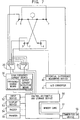
- a body composition measuring instrument as shown in the figure comprises total ten electrodes. More particularly one high frequency current application electrode and one potential difference measurement electrode are mounted on each of both hands and both feet which are extreme parts of a body. In addition, one potential difference measurement electrode is mounted on each of the roots of both arms.
- reference numerals 1, 2, 3 and 4 represent the high frequency current application electrodes for applying high frequency current to the body. Those electrodes 1, 2, 3 and 4 are connected to switching means 20 and 21 which are then connected to output terminals of a high frequency current source 30. Electrodes 5, 6, 7, 8, 9 and 10 are connected to switching means 21, 22 and 23. The switching means 22 and 23 are connected to a potential difference measuring device 40, and the switching means 21 is connected to output terminals of the high frequency current source 30. The electrodes 5, 6, 7, 8, 9 and 10 are used for measurement of potential difference, but they may also act as the high frequency current application electrodes for applying high frequency current to the body.
- the switching means 20, 21, 22 and 23 are connected to a control, arithmetic and storage device 50 so that they can independently operate to switch the electrodes according to control signals from the device 50.
- the high frequency current source 30 connected to the switching means 20 and 21 comprises a current detection means for detecting its output current and a frequency change means for changing the frequency of high frequency current, both means are connected to the control, arithmetic and storage device 50.
- the current detection means functions to inform the detection result to the arithmetic and storage device 50
- the frequency change means functions to change the frequency of high frequency current according to the control signals from the control, arithmetic and storage device 50.
- the switching means 22 and 23 are connected to the potential difference measuring device 40 whose output is connected to the control, arithmetic and storage device 50 via an A/D converter 41.
- the A/D converter 41 functions to convert the output of the potential difference measuring device 40 into digital values which are then fed to the control, arithmetic and storage device 50.
- An input device 52 is connected to the control, arithmetic and storage device 50 for entering some instructions for operations of the system and parameters for a person to be tested such as height and weight of the person.
- a display device 53 connected to the control, arithmetic and storage device 50 functions to display parameter settings for the person to be tested, measurement results, and some indications indicating when an error occurs.
- a buzzer 54 is activated to generate a tone at the time when the measurement is started, the measurement is completed, and any error occurs.
- a printer 55 produces a hard copy of the measurement results.
- a communication device 56 is connected to the control, arithmetic and storage device 50 in order to communicate between the system and the external devices.
- the communication device 56 functions to transmit the measurement results to the external devices, while it receives the parameters for the person to be tested and the instructions for operation of the system from the external devices.
- a memory card is used for the removable storage medium.
- the parameters used for the measurement and the data such as the measurement results are stored in the memory card through the control, arithmetic and storage device 50.
- the control, arithmetic and storage device 50 functions to selectively activate the switching means 20, 21, 22 and 23 and to control changing of the frequency of the high frequency current.
- the device 50 functions to perform an arithmetic operation, based on the data or parameters for the person to be tested (which are entered from the input device, the communication device and the memory card), as well as on the data obtained by the measurement. As the result, the device 50 produces the values of impedance and the body composition, which are then fed to the output devices, the communication device and the memory card.
- Fig. 10 shows the flow of the measurement steps.
- the same electrode is selected by the switching means 20 and 21. This is for the purpose of self-diagnosis for finding out whether the output current is at normal level or at abnormal level. If it is found that the output current is at abnormal level, the measurement is stopped with an indication on the display device that indicates some abnormal condition prevailing in the system.
- the parameters for the person to be tested and the instructions for operations of the system are entered by the input device 52. Then, the electrodes are attached to both hands, both feet and the roots of both arms.
- any two different electrodes are selected by the switching means 20 and 21, and the check is made to see if the current passing therebetween is at normal level or not. If an abnormal current passes, it means that any one of or both of the electrodes selected is in poor contact or no contact condition.
- one of the electrodes 2 to 10 is sequentially selected by the switching means 21 for examination. If it is found that an abnormal current passes when the electrodes 5 and 10 are selected, it means that the electrodes 5 and 10 are in poor contact or no contact condition. It may happen that all the electrodes 2 to 10 are found abnormal after they are sequentially selected by the switching means 21. In such case, the electrodes 2 is kept selected by the switching means 20 and any one of the electrodes 3 to 10 is sequentially selected by the switching means 21. In such manner, any poor contact or no contact condition of the electrodes can be detected.
- the examination of the electrode contact condition can be performed depending on whether the current passing to the body from the high frequency current source is at normal level, or within the normal range, or at abnormal level. This greatly reduces the time period required for the examination. In view of such examination made before starting the measurement, it is unlikely that the measurement process would inevitably be interrupted in the course of measurement due to any defective contact of the electrodes.
- the buzzer device may sound and/or the display device may display which electrode (or electrodes) is in poor contact or no contact condition, or which electrode is becoming to such condition.
- Fig. 2 that is the equivalent circuit diagram of the human body
- Z1" and “Z2" mean the impedance of arms
- Z3" and “Z4" mean the impedance of the chest portion
- Z5" means the impedance of the abdominal region
- Z6" and “Z7” mean the impedance of legs.
- the electrodes 1 and 5 are attached to and brought into contact with the right hand.
- the electrodes 2 and 6 are attached to the left hand.
- the electrodes 3 and 7 are attached to the right foot.
- the electrodes 4 and 8 are attached to the left foot.
- the electrode 9 is attached to the root of the right arm
- the electrode 10 is attached to the root of the left arm.
- the impedance "Z1" is called a "right arm impedance”; "Z2" a “left arm impedance”; “Z3” a “right chest impedance”; “Z4" a “left chest impedance”; “Z5" a “abdominal impedance”; “Z6” a “right leg impedance”; and “Z7” a "left leg impedance”.
- the electrode 1 is selected by the switching means 20, the electrode 3 is selected by the switching means 21, the electrode 8 is selected by the switching means 22, and the electrode 7 is selected by the switching means 23.
- the electrode 2 is selected by the switching means 20
- the electrode 4 is selected by the switching means 21
- the electrode 7 is selected by the switching means 22, and the electrode 8 is selected by the switching means 23.
- the left leg impedance Z7 can be derived.
- the electrode 1 is selected by the switching means 20, the electrode 3 is selected by the switching means 21, the electrode 6 is selected by the switching means 22, and the electrode 8 is selected by the switching means 23.
- the electrode 1 is selected by the switching means 20, the electrode 3 is selected by the switching means 21, the electrode 5 is selected by the switching means 22, and the electrode 9 is selected by the switching means 23.
- the right arm impedance Z1 can be derived.
- the electrode 2 is selected by the switching means 20
- the electrode 4 is selected by the switching means 21
- the electrode 6 is selected by the switching means 22
- the electrode 10 is selected by the switching means 23.
- the left arm impedance Z2 can be derived.
- the electrode 1 is selected by the switching means 20, the electrode 3 is selected by the switching means 21, the electrode 9 is selected by the switching means 22, and the electrode 10 is selected by the switching means 23.
- the electrode 2 is selected by the switching means 20
- the electrode 4 is selected by the switching means 21
- the electrode 10 is selected by the switching means 22, and the electrode 9 is selected by the switching means 23.
- the left chest impedance Z4 can be derived.
- the impedance on each of the parts of the body as shown in Fig. 2 are measured in accordance with 4-terminal law.
- the measurement results are transmitted to the control, arithmetic and storage device 50.
- the data such as the parameters of the person to be tested are entered and stored in the control, arithmetic and storage device 50 by using the input device in advance.
- the control, arithmetic and storage device 50 performs the arithmetic operations based on the measurement results and the parameter data to produce the body composition in part of or in whole of the body as well as the distribution for each of the composition components.
- the difference in right-to-left of the arms, chest portions and legs can be derived and they are output to the display device for indication.
- the impedance measurement is performed again, but with the change in frequency of the high frequency current, and "Cole-Cole plot law" is applied to the measurement results. Then, the amount of intracellular or extracellular fluid as well as the water content in each of the parts of the body can be derived.
- the measurement results and the parameters of a persons to be tested can partly or wholly be output to the printer device for printing, or transmitted to the external devices via the communication device, or stored in the memory card, depending on the applications, under the control of the control, arithmetic and storage device 50.
- FIG. 8 another embodiment of the present invention is shown in which two high frequency current application electrodes are each attached to the right hand and the right foot, and four potential difference measurement electrodes are each attached to both hands and both foot.
- each of the impedance "Z1 + Z3", “Z5" and “Z6" can be determined in one measurement operation simply by changing the measurement path.
- two high frequency current application electrodes are each attached to both hands, and four potential difference measurement electrodes are each attached to both hands and to the roots of both arms.
- the impedance "Z1" and "Z2" can be determined by changing the potential difference measurement path.
- FIG. 7 further embodiment of the present invention is shown in which two potential difference measurement electrodes are each attached to the right hand and the right foot, and four high frequency current application electrodes are each attached to both hands and both feet.
- each of the impedance "Z1+Z3", “Z5" and “Z6" can be determined in one measurement operation simply by changing the current application path.
- a pair of the high frequency current application electrode and the potential difference measurement electrode is attached to both hands and both feet, respectively.
- each of the impedance "Z1+Z3", “Z2+Z4", “Z5", “Z6” and”Z7" for all the parts of the body can be determined in one measurement operation by independently changing the current application path and the potential difference measurement path.
- the living impedance on each of the parts of a human body can easily be measured so that calculation and assessment of the body composition on each of the parts can be performed. Therefore, the whole body composition derived from such results is contributed by the living impedance information in whole body, thereby improving the accuracy in measurement for the whole body composition.
- the composition on only a part of the body is known, the measurement on only that part of the body can be done. It takes shorter time period and relieves the discomfort of a person to be tested.
- the information indicating the parts of the body to be measured and the changing sequence of the electrodes required for the measurement may be entered to the system in advance as the measurement parameters.
- any specified part of the body can be measured simply by selecting any one of the parameters without any complicated operation.
- Such measurement and operation can easily be done by everybody or unskilled person.
Landscapes
- Health & Medical Sciences (AREA)
- Life Sciences & Earth Sciences (AREA)
- Medical Informatics (AREA)
- Molecular Biology (AREA)
- Veterinary Medicine (AREA)
- Biophysics (AREA)
- Pathology (AREA)
- Engineering & Computer Science (AREA)
- Biomedical Technology (AREA)
- Heart & Thoracic Surgery (AREA)
- Public Health (AREA)
- Physics & Mathematics (AREA)
- Surgery (AREA)
- Animal Behavior & Ethology (AREA)
- General Health & Medical Sciences (AREA)
- Cardiology (AREA)
- Nuclear Medicine, Radiotherapy & Molecular Imaging (AREA)
- Radiology & Medical Imaging (AREA)
- Vascular Medicine (AREA)
- Physiology (AREA)
- Measurement And Recording Of Electrical Phenomena And Electrical Characteristics Of The Living Body (AREA)
- Investigating Or Analyzing Materials By The Use Of Electric Means (AREA)
Applications Claiming Priority (3)
| Application Number | Priority Date | Filing Date | Title |
|---|---|---|---|
| JP5424497 | 1997-02-24 | ||
| JP5424497 | 1997-02-24 | ||
| PCT/JP1998/000736 WO1998036686A1 (en) | 1997-02-24 | 1998-02-24 | Living body impedance measuring instrument and body composition measuring instrument |
Publications (2)
| Publication Number | Publication Date |
|---|---|
| EP1013221A1 true EP1013221A1 (de) | 2000-06-28 |
| EP1013221A4 EP1013221A4 (de) | 2001-05-02 |
Family
ID=12965138
Family Applications (1)
| Application Number | Title | Priority Date | Filing Date |
|---|---|---|---|
| EP98904425A Withdrawn EP1013221A4 (de) | 1997-02-24 | 1998-02-24 | Messgerät für die impedanz eines lebenden körpers und für die zusammensetzung des körpers |
Country Status (5)
| Country | Link |
|---|---|
| US (1) | US6393317B1 (de) |
| EP (1) | EP1013221A4 (de) |
| KR (1) | KR20000075585A (de) |
| AU (1) | AU6230298A (de) |
| WO (1) | WO1998036686A1 (de) |
Cited By (3)
| Publication number | Priority date | Publication date | Assignee | Title |
|---|---|---|---|---|
| WO2004048983A1 (en) * | 2002-11-27 | 2004-06-10 | Z-Tech (Canada) Inc. | Improved apparatus and method for performing impedance measurements |
| US6790178B1 (en) * | 1999-09-24 | 2004-09-14 | Healthetech, Inc. | Physiological monitor and associated computation, display and communication unit |
| EP1917907A1 (de) * | 2000-12-28 | 2008-05-07 | Z-Tech (Canada) Inc. | Elektrisches Impedanzverfahren und Vorrichtung zur Erkennung und Diagnose von Erkrankungen |
Families Citing this family (43)
| Publication number | Priority date | Publication date | Assignee | Title |
|---|---|---|---|---|
| US6141585A (en) * | 1998-05-08 | 2000-10-31 | Intermedics Inc. | Implantable cardiac stimulator with electrode-tissue interface characterization |
| JP4357049B2 (ja) * | 1999-10-07 | 2009-11-04 | 大和製衡株式会社 | 体内脂肪測定装置 |
| JP4530232B2 (ja) * | 1999-10-12 | 2010-08-25 | 株式会社タニタ | 生体測定装置 |
| US6482158B2 (en) | 2000-05-19 | 2002-11-19 | Healthetech, Inc. | System and method of ultrasonic mammography |
| JP4671467B2 (ja) * | 2000-05-31 | 2011-04-20 | 大和製衡株式会社 | インピーダンス測定装置 |
| JP4632490B2 (ja) * | 2000-07-18 | 2011-02-16 | 大和製衡株式会社 | 体内脂肪量測定装置 |
| US6865410B2 (en) * | 2000-08-04 | 2005-03-08 | Electric Power Research Institute, Inc. | Apparatus and method for measuring current flow in an animal or human body |
| AU2001296456A1 (en) | 2000-09-29 | 2002-04-08 | Healthetech, Inc. | Indirect calorimetry system |
| JP3698633B2 (ja) * | 2000-10-25 | 2005-09-21 | 株式会社タニタ | 体型判定装置 |
| US6607387B2 (en) | 2000-10-30 | 2003-08-19 | Healthetech, Inc. | Sensor system for diagnosing dental conditions |
| JP4671490B2 (ja) * | 2000-11-17 | 2011-04-20 | 大和製衡株式会社 | 身体インピーダンス測定装置 |
| GB0106250D0 (en) * | 2001-03-13 | 2001-05-02 | Hall Effect Technologies Ltd | Apparatus and method for analysing blood |
| US6625487B2 (en) * | 2001-07-17 | 2003-09-23 | Koninklijke Philips Electronics N.V. | Bioelectrical impedance ECG measurement and defibrillator implementing same |
| JP3653519B2 (ja) * | 2002-06-12 | 2005-05-25 | ヤーマン株式会社 | 体内構成測定装置 |
| JP2004329412A (ja) * | 2003-05-02 | 2004-11-25 | Tanita Corp | 体組成測定装置 |
| JP4600914B2 (ja) * | 2003-10-08 | 2010-12-22 | 株式会社タニタ | 体型判定装置 |
| JP2006198334A (ja) * | 2005-01-24 | 2006-08-03 | Tanita Corp | 生体電気インピーダンス測定装置及び体組成測定装置 |
| JP4529884B2 (ja) * | 2005-11-30 | 2010-08-25 | オムロンヘルスケア株式会社 | 体脂肪測定装置および上肢ユニット |
| JP4529913B2 (ja) * | 2006-01-18 | 2010-08-25 | オムロンヘルスケア株式会社 | 体組成計 |
| JP4762765B2 (ja) * | 2006-03-17 | 2011-08-31 | 富士通株式会社 | 生体検知装置、指紋認証装置、及び生体検知方法 |
| US8109883B2 (en) | 2006-09-28 | 2012-02-07 | Tyco Healthcare Group Lp | Cable monitoring apparatus |
| US8668651B2 (en) | 2006-12-05 | 2014-03-11 | Covidien Lp | ECG lead set and ECG adapter system |
| JP4812735B2 (ja) * | 2007-11-15 | 2011-11-09 | 大和製衡株式会社 | 体内脂肪計 |
| CA2646037C (en) | 2007-12-11 | 2017-11-28 | Tyco Healthcare Group Lp | Ecg electrode connector |
| US8548558B2 (en) * | 2008-03-06 | 2013-10-01 | Covidien Lp | Electrode capable of attachment to a garment, system, and methods of manufacturing |
| US20090227857A1 (en) * | 2008-03-06 | 2009-09-10 | Chuck Rowe | Biomedical electrode |
| US8868216B2 (en) * | 2008-11-21 | 2014-10-21 | Covidien Lp | Electrode garment |
| USD737979S1 (en) | 2008-12-09 | 2015-09-01 | Covidien Lp | ECG electrode connector |
| EP2305111A1 (de) * | 2009-10-01 | 2011-04-06 | seca ag | Bioimpedanzmessvorrichtung und -verfahren |
| US8694080B2 (en) | 2009-10-21 | 2014-04-08 | Covidien Lp | ECG lead system |
| CA2746944C (en) | 2010-07-29 | 2018-09-25 | Tyco Healthcare Group Lp | Ecg adapter system and method |
| ES2762190T3 (es) | 2011-07-22 | 2020-05-22 | Kpr Us Llc | Conector de electrodo ECG |
| US8634901B2 (en) | 2011-09-30 | 2014-01-21 | Covidien Lp | ECG leadwire system with noise suppression and related methods |
| WO2013075270A1 (zh) * | 2011-11-25 | 2013-05-30 | Yang Chang-Ming | 一种侦测心跳或电极接触良好与否的物品、方法及系统 |
| CN102920454B (zh) * | 2012-06-26 | 2014-09-17 | 北京四海华辰科技有限公司 | 一种人体阻抗测量方法、装置及设备 |
| CN103123669B (zh) * | 2013-02-28 | 2016-03-30 | 大连大学 | 一种基于遗传算法的人体体成分分析方法 |
| USD771818S1 (en) | 2013-03-15 | 2016-11-15 | Covidien Lp | ECG electrode connector |
| US9408546B2 (en) | 2013-03-15 | 2016-08-09 | Covidien Lp | Radiolucent ECG electrode system |
| DK2967396T3 (da) | 2013-03-15 | 2019-05-20 | Kpr Us Llc | Elektrodekonnektor med et ledende element |
| JP2017514620A (ja) * | 2014-05-07 | 2017-06-08 | コーニンクレッカ フィリップス エヌ ヴェKoninklijke Philips N.V. | 対象の体の部分の流体内容を推定する方法及び装置 |
| KR102265066B1 (ko) | 2014-07-17 | 2021-06-15 | 삼성전자주식회사 | 생체 임피던스 측정 방법 및 장치 |
| JP7767288B2 (ja) | 2019-12-23 | 2025-11-11 | アリメトリー リミテッド | 電極パッチおよび接続システム |
| WO2022265446A1 (en) * | 2021-06-18 | 2022-12-22 | Samsung Electronics Co., Ltd. | Device and method for human body impedance analysis insensitive to high contact impedance and parasitic effects |
Family Cites Families (17)
| Publication number | Priority date | Publication date | Assignee | Title |
|---|---|---|---|---|
| FR2224804B1 (de) | 1973-04-09 | 1976-12-17 | Siemens Ag | |
| JPS5244420Y2 (de) * | 1973-05-29 | 1977-10-08 | ||
| US4008721A (en) | 1975-04-14 | 1977-02-22 | Medtronic, Inc. | Tape electrode for transmitting electrical signals through the skin |
| US4008712A (en) | 1975-11-14 | 1977-02-22 | J. M. Richards Laboratories | Method for monitoring body characteristics |
| JPH052164Y2 (de) * | 1987-05-27 | 1993-01-20 | ||
| JP2830082B2 (ja) | 1989-06-23 | 1998-12-02 | 三菱化学株式会社 | 静電荷像現像用現像剤 |
| JPH0549050A (ja) | 1991-08-09 | 1993-02-26 | Sony Corp | Crt調整装置 |
| GB9222888D0 (en) * | 1992-10-30 | 1992-12-16 | British Tech Group | Tomography |
| JPH0712635A (ja) * | 1993-06-25 | 1995-01-17 | Ya Man Ltd | 体脂肪測定装置 |
| US5579782A (en) * | 1993-08-12 | 1996-12-03 | Omron Corporation | Device to provide data as a guide to health management |
| JP3211118B2 (ja) | 1993-09-14 | 2001-09-25 | オムロン株式会社 | 健康管理指針アドバイス装置 |
| US5824029A (en) * | 1994-04-28 | 1998-10-20 | Medtronic, Inc. | Implantable medical system for performing transthoracic impedance measurements associated with cardiac function |
| JP3240401B2 (ja) * | 1994-12-07 | 2001-12-17 | オムロン株式会社 | インピーダンス測定装置および健康管理指針アドバイス装置 |
| JP3409095B2 (ja) | 1994-12-07 | 2003-05-19 | オムロン株式会社 | インピーダンス測定装置および健康管理指針アドバイス装置 |
| US6044294A (en) * | 1995-12-15 | 2000-03-28 | Pacesetter, Inc. | Methods and apparatus for measuring impedance in the body |
| JPH09285455A (ja) | 1996-02-23 | 1997-11-04 | Omron Corp | 健康管理指針アドバイス装置 |
| US6058325A (en) * | 1996-04-16 | 2000-05-02 | Cardiotronics | Method and apparatus for high current electrode, transthoracic and transmyocardial impedance estimation |
-
1998
- 1998-02-24 US US09/367,349 patent/US6393317B1/en not_active Expired - Lifetime
- 1998-02-24 EP EP98904425A patent/EP1013221A4/de not_active Withdrawn
- 1998-02-24 WO PCT/JP1998/000736 patent/WO1998036686A1/ja not_active Ceased
- 1998-02-24 AU AU62302/98A patent/AU6230298A/en not_active Abandoned
- 1998-02-24 KR KR1019997007645A patent/KR20000075585A/ko not_active Ceased
Cited By (3)
| Publication number | Priority date | Publication date | Assignee | Title |
|---|---|---|---|---|
| US6790178B1 (en) * | 1999-09-24 | 2004-09-14 | Healthetech, Inc. | Physiological monitor and associated computation, display and communication unit |
| EP1917907A1 (de) * | 2000-12-28 | 2008-05-07 | Z-Tech (Canada) Inc. | Elektrisches Impedanzverfahren und Vorrichtung zur Erkennung und Diagnose von Erkrankungen |
| WO2004048983A1 (en) * | 2002-11-27 | 2004-06-10 | Z-Tech (Canada) Inc. | Improved apparatus and method for performing impedance measurements |
Also Published As
| Publication number | Publication date |
|---|---|
| KR20000075585A (ko) | 2000-12-15 |
| EP1013221A4 (de) | 2001-05-02 |
| US6393317B1 (en) | 2002-05-21 |
| WO1998036686A1 (en) | 1998-08-27 |
| AU6230298A (en) | 1998-09-09 |
Similar Documents
| Publication | Publication Date | Title |
|---|---|---|
| EP1013221A1 (de) | Messgerät für die impedanz eines lebenden körpers und für die zusammensetzung des körpers | |
| KR100372370B1 (ko) | 체지방측정장치 및 체지방측정장치를 구비한 체중계 | |
| EP1063500B9 (de) | Verfahren und Vorrichtung zur Messung der Verteilung von Körperfettgehalt | |
| JPH10510455A (ja) | 生体電気インピーダンス分析に基づく新しい電極システムを用いた人体成分分析装置及び分析方法 | |
| GB2304414A (en) | System for body impedance data acquisition utilizing segmental impedance and multiple frequency impedance measurement | |
| US7110809B2 (en) | Muscle fatigue measuring equipment | |
| JP2008229364A (ja) | 健康管理装置 | |
| JP5110277B2 (ja) | 身体組成推計装置及び身体組成推計方法 | |
| JPH0549050B2 (de) | ||
| JPH1170090A (ja) | 生体電気インピーダンス測定装置 | |
| JPH10185A (ja) | 体液異常診断装置 | |
| US20230233146A1 (en) | Edema detection | |
| JP3636825B2 (ja) | 体脂肪測定装置 | |
| Burke et al. | Middle ear impedance measurements | |
| Popelka | Acoustic immittance measures: Terminology and instrumentation | |
| Siervogel et al. | Bioelectric impedance measures of body composition: their relationship with level of blood pressure in young adults | |
| JP3636824B2 (ja) | 体脂肪測定装置 | |
| RU2018297C1 (ru) | Способ диагностики отоневрологических синдромов и устройство для его осуществления | |
| JP2001104270A (ja) | 体脂肪計、体脂肪計を用いた皮膚インピーダンスに関する測定方法、体脂肪の測定方法 | |
| JP3819611B2 (ja) | 身体組成推計装置 | |
| US20220400973A1 (en) | Method, a device, and a system for estimating total body water content | |
| RU2122347C1 (ru) | Способ съема данных о состоянии биологически активных точек тела человека | |
| JPWO1998036686A1 (ja) | 生体インピーダンス測定装置及び身体組成測定装置 | |
| JP4359292B2 (ja) | 身体組成推計装置 | |
| JP2005131434A (ja) | 身体組成推計装置 |
Legal Events
| Date | Code | Title | Description |
|---|---|---|---|
| PUAI | Public reference made under article 153(3) epc to a published international application that has entered the european phase |
Free format text: ORIGINAL CODE: 0009012 |
|
| 17P | Request for examination filed |
Effective date: 19990916 |
|
| AK | Designated contracting states |
Kind code of ref document: A1 Designated state(s): DE FR GB |
|
| A4 | Supplementary search report drawn up and despatched |
Effective date: 20010322 |
|
| AK | Designated contracting states |
Kind code of ref document: A4 Designated state(s): DE FR GB |
|
| 17Q | First examination report despatched |
Effective date: 20030929 |
|
| STAA | Information on the status of an ep patent application or granted ep patent |
Free format text: STATUS: THE APPLICATION IS DEEMED TO BE WITHDRAWN |
|
| 18D | Application deemed to be withdrawn |
Effective date: 20041216 |