EP1013232B1 - Guide pour perceuse se repérant à l'axe épicondylaire - Google Patents
Guide pour perceuse se repérant à l'axe épicondylaire Download PDFInfo
- Publication number
- EP1013232B1 EP1013232B1 EP99310229A EP99310229A EP1013232B1 EP 1013232 B1 EP1013232 B1 EP 1013232B1 EP 99310229 A EP99310229 A EP 99310229A EP 99310229 A EP99310229 A EP 99310229A EP 1013232 B1 EP1013232 B1 EP 1013232B1
- Authority
- EP
- European Patent Office
- Prior art keywords
- central body
- bone
- assembly
- jig
- positioning
- Prior art date
- Legal status (The legal status is an assumption and is not a legal conclusion. Google has not performed a legal analysis and makes no representation as to the accuracy of the status listed.)
- Expired - Lifetime
Links
- 0 CCC1C2(C3)C3=C*C12 Chemical compound CCC1C2(C3)C3=C*C12 0.000 description 1
Images


Classifications
-
- A—HUMAN NECESSITIES
- A61—MEDICAL OR VETERINARY SCIENCE; HYGIENE
- A61B—DIAGNOSIS; SURGERY; IDENTIFICATION
- A61B17/00—Surgical instruments, devices or methods
- A61B17/14—Surgical saws
- A61B17/15—Guides therefor
- A61B17/154—Guides therefor for preparing bone for knee prosthesis
- A61B17/155—Cutting femur
-
- A—HUMAN NECESSITIES
- A61—MEDICAL OR VETERINARY SCIENCE; HYGIENE
- A61F—FILTERS IMPLANTABLE INTO BLOOD VESSELS; PROSTHESES; DEVICES PROVIDING PATENCY TO, OR PREVENTING COLLAPSING OF, TUBULAR STRUCTURES OF THE BODY, e.g. STENTS; ORTHOPAEDIC, NURSING OR CONTRACEPTIVE DEVICES; FOMENTATION; TREATMENT OR PROTECTION OF EYES OR EARS; BANDAGES, DRESSINGS OR ABSORBENT PADS; FIRST-AID KITS
- A61F2/00—Filters implantable into blood vessels; Prostheses, i.e. artificial substitutes or replacements for parts of the body; Appliances for connecting them with the body; Devices providing patency to, or preventing collapsing of, tubular structures of the body, e.g. stents
- A61F2/02—Prostheses implantable into the body
- A61F2/30—Joints
- A61F2/38—Joints for elbows or knees
- A61F2/3859—Femoral components
-
- A—HUMAN NECESSITIES
- A61—MEDICAL OR VETERINARY SCIENCE; HYGIENE
- A61F—FILTERS IMPLANTABLE INTO BLOOD VESSELS; PROSTHESES; DEVICES PROVIDING PATENCY TO, OR PREVENTING COLLAPSING OF, TUBULAR STRUCTURES OF THE BODY, e.g. STENTS; ORTHOPAEDIC, NURSING OR CONTRACEPTIVE DEVICES; FOMENTATION; TREATMENT OR PROTECTION OF EYES OR EARS; BANDAGES, DRESSINGS OR ABSORBENT PADS; FIRST-AID KITS
- A61F2/00—Filters implantable into blood vessels; Prostheses, i.e. artificial substitutes or replacements for parts of the body; Appliances for connecting them with the body; Devices providing patency to, or preventing collapsing of, tubular structures of the body, e.g. stents
- A61F2/02—Prostheses implantable into the body
- A61F2/30—Joints
- A61F2/46—Special tools for implanting artificial joints
- A61F2/4684—Trial or dummy prostheses
-
- A—HUMAN NECESSITIES
- A61—MEDICAL OR VETERINARY SCIENCE; HYGIENE
- A61F—FILTERS IMPLANTABLE INTO BLOOD VESSELS; PROSTHESES; DEVICES PROVIDING PATENCY TO, OR PREVENTING COLLAPSING OF, TUBULAR STRUCTURES OF THE BODY, e.g. STENTS; ORTHOPAEDIC, NURSING OR CONTRACEPTIVE DEVICES; FOMENTATION; TREATMENT OR PROTECTION OF EYES OR EARS; BANDAGES, DRESSINGS OR ABSORBENT PADS; FIRST-AID KITS
- A61F2/00—Filters implantable into blood vessels; Prostheses, i.e. artificial substitutes or replacements for parts of the body; Appliances for connecting them with the body; Devices providing patency to, or preventing collapsing of, tubular structures of the body, e.g. stents
- A61F2/02—Prostheses implantable into the body
- A61F2/30—Joints
- A61F2/46—Special tools for implanting artificial joints
- A61F2/4657—Measuring instruments used for implanting artificial joints
- A61F2002/4658—Measuring instruments used for implanting artificial joints for measuring dimensions, e.g. length
Definitions
- the present invention relates to tools and jigs for laying out machine cuts to prepare a bone for receiving a correctly sized and aligned prosthetic component, such as a component of a prosthetic knee joint assembly.
- the surgical preparation of bone endings for receiving prosthetic knee joints for a total knee replacement is generally a complex procedure, particularly when ligament remain attached, or when osteoarthritic changes to the joint have distorted the normal bone endings or the articulation geometry of the joint or bone.
- it i s necessary to determine a number of positioning pin locations, form a number of flat surface cuts, and carry out a soft tissue balancing procedure.
- Numerous specially aligned cuts at the bone ends are necessary in order to install the prosthetic component with correct spacing, alignment and tensioning to prevent improper kinematics from arising as the joint rotates in use, and to avoid the occurrence of accelerated wear patterns or possible joint dislocation.
- the bone cuts made to effect the placement and orientation of the femoral component of the prosthesis determine and form the joint gaps in extension and flexion.
- the size and shape of these two gaps affect final bone orientation as well as joint tensioning and clearances, and the femur must be so oriented, with respect to the cut surfaces defining the prosthesis fit, so as to satisfy numerous constraints.
- the flexion gap is related to internal/external orientation of the femur, while the extension gap is related to the varus/valgus orientation of the femur.
- these cuts are formed so that in extension the joint gap is perpendicular to the mechanical axis of the femur, while in flexion the joint gap is such as to place the femoral component in either neutral or external rotation and assure proper patellar tracking with the femoral component.
- the gaps created by the bone resections in both flexion and extension should be rectangular.
- the relevant natural articulation surface corresponds to the tangent plane of the posterior epicondyles, and in extension, to that of the distal epicondylar surface.
- A/P cuts by reference to the posterior surfaces, there is some risk of notching the anterior cortex.
- many surgeons set the A/P cut positions with reference to the anterior cortex.
- the fining is done by first resecting the distal femur, then drilling positioning holes for the femoral joint component positioning pins and subsequently placing one or more cutting blocks of a standard set of blocks, or other tool alignment assemblies, into the positioning holes to guide the necessary cut in the femur.
- the epicondylar axis as a guide line, either by marking its position as a reference for confirming alignment or making slight adjustments during fitting, or as a primary landmark when disease or a previous arthroplasty have altered or obliterated the usual primary landmarks.
- this provides improved balance of the collateral ligament tension between flexion and full extension.
- it can be awkward to determine the epicondylar axis, and while the clinical epicondylar prominence may be considered in advance of surgery, this feature varies somewhat from a true geometric center of the articulation axis.
- the epicondylar axis is generally marked on the distal femoral cut surface, when the leg is in flexion, viewing the exposed epicondyles head-on. Thereafter, the surgeon may use the marked line to harmonize or check the preparatory cuts or axes determined by other measurement jigs and empirical offsets, such as to adjust an axis original set parallel to the posterior epicondylar tangent plane, or a fitting referenced to the trochlear groove.
- the resulting sequence of steps may be complex and time consuming.
- the body Before making a determinative cut or drill hole, the body may be shifted laterally to optimize the component position for load bearing or patella tracking. Once positioned, the body is immobilized by an impact which sets protruding barbs into the bone surface, and the holes are then drilled to accommodate the positioning pins of a standard set of cutting blocks.
- the present invention is a tool which simplifies the procedure of preparing the distal femoral end for a prosthetic implant by allowing the surgeon to conveniently size the femur and position components in relation to the epicondylar axis using a single instrument.
- the mechanical arrangement of various components of the tool in a prototype embodiment 100 will be appreciated from discussion of the figures below, illustrating representative structures and their manner of use.
- a first prototype tool 100 is intended for use during surgery, and has a body which lies across the distal resected end 21 of a femur 20 which may be either the right or left femur.
- the tool is preferably used once the surgeon has made the distal femoral cut, and includes a central body 60 which includes a drill guide 61, and which is positioned across the distal bone end by an axis- or line-referencing assembly, discussed more fully below.
- the line-referencing assembly is implemented by a simple pair of viewing apertures or slots 65 in the body 60.
- the body 60 has been placed by the surgeon so that the apertures 65 are directly over a line or pair of marks 25a, 25b which are previously scribed by the surgeon to mark the projection of the epicondylar axis on the distal bone surface. So positioned, the body 60 places the drill guide holes 61 on the axis. As further shown, the body includes size graduations for the medial/lateral sizing of the femoral prosthetic component, which are arranged as a stepped array 68 of scale markings around the circumference of the body 60, allowing the surgeon to separately size the medial and lateral lobes of the femoral ending by viewing the peripheral outline against the scale markings.
- the body 60 rides on a vertical post or rail 82 which forms a part of an A/P positioning assembly 80, configured as a cortex arm 84 and stylus 84a as discussed further below.
- the post 82 has a stepped cross section, forming a slide rail for uniaxial sliding movement in a T-slot or mating groove 64 that is formed in the body 60.
- the cortex arm 84 in some embodiments may be configured to slide in the direction 85 through its mounting aperture in the post 82, so that the tip 84b of the stylus may be brought into position immediately behind the terminal protuberances of the distal femur.
- the slidable carriage of the drill positioning guide 60 on the post 82 of which the A/P position is set allows the positioning pin holes for a prosthesis and/ or preparatory cutting blocks to be laid out and drilled on the bone end in the correct A/P offset while the body 60 is simultaneously oriented by the epicondylar axis sighting assembly 65 in alignment along the epicondylar axis.
- a first set of sizing graduations 68a, 68b and a second set of graduations 88 aid in determining an appropriate size femoral component, or in adjusting the size, by reference to the medial/lateral and A/P position of the assembly on the resected end surface 21.
- the component size may be estimated taking into account the relative extent of the existing features.
- the drill positioning body of the tool 100 may be freely moved across the distal end of the femur and as shown in Figure 1, permit visualization of the femoral shape in relation to the various settings or graduations of the tool and simultaneously perform sizing and A/P positioning.
- a pair of positioning barbs 61a, 61b project slightly from the posterior (bone contacting) face of the body 60 so that once placed in an appropriate position, a slight tap or pressure will fix the body and prevent further sliding or rotation, thus stably setting the cutting tool position.
- the cortex positioning bar 84 extends transversely to the plane of the tool alignment body 60 from the central rail or post 82.
- this arm provides a further sighting or referencing feature for aligning the assembly with respect to the bone. It will be observed that the contact point 84b at the tip of the stylus 84a essentially suspends the body 60 on the arm 84 so that it may be rocked or shifted.
- the bar 84 is positioned so that it rests in the trochlear notch of the femur, between the epicondyles and the plate is shifted side-to-side, so that the bar 84 becomes aligned more closely along the groove normally tracked by the patella.
- the cortex bar 84 is first set at a minimal A/P size position, for example by sliding post 82 in the tracking groove 64 of body 60 to a small size or low size graduation mark on the scale 88, thus making the drill positioning sizing body 60 ride very close to the arm.
- the arm 84 is then nestled down into the patellar notch of the femur and brought into longitudinal alignment with the groove.
- the body 60 then lies centered in a position for optimal tracking of the patellar component of the joint.
- the body 60 may then be raised or lowered along the post 82 until it is approximately centered with respect to the A/P direction on the end of the femur, as illustrated in Figure 1.
- the graduation scale 88 will then read the correct A/P prosthesis size.
- the respective left and right sets of medial/lateral femoral component size designations 68a, 68b will then display the optimal size femoral component as determined from the bone geometry on the left and right sides of the center post.
- the odd size graduations are indicated on the upper steps, and the even sizes on the lower steps, to accommodate a greater number of specific sizes in the limited horizontal range between the lowest (1.5) and the highest (6.0) femoral component size graduations.
- Other graduation schemes may be used, for example placing the numbers at the ends of lines which curve obliquely out to the edges of the body 60.
- the bone when shifted to one side or the other to follow the trochlear groove with the cortex hook, the bone may well be asymmetrically positioned and indicate a size three component on the medial edge and a size five component on the lateral edge, or show some similar discrepancy between optimal size indications.
- the foregoing feature allows the tool to undergo a forced lateral translation in order to select and position a femoral component to achieve optimal patellar tracking in view of the geometry of the bone.
- the fit of the standard size femoral components may be visually observed in relation to the medial epicondyle, the lateral epicondyle, and the trochlear notch so that adjustments to suit the geometry of the particular bone are readily made before positioning the barbs 61a, 61b and placing the drill holes 61 which will determine all subsequent cuts and chamfers.
- the tool of the present invention may also be used by first positioning the body 60 symmetrically on the end face of the femur, and then using the A/P positioning assembly 80 simply to determine the correct A/P size.
- the drill guide holes 61a, 61b illustrated in Figure 1 correspond to a pair of positioning pins having a fixed spacing as used for example by one prosthesis manufacturer in all sizes of a line of femoral components.
- this system employs a sequence of cutting blocks and other tools for preparing subsequent chamfers and faces of the bone termination which are also set, justified or otherwise positioned by the same two pin locating holes.
- the tool locator body 60 may be adapted in other embodiment as a saw cut guide rather than a drill guide, or both, in order to position a slot or other cut feature which similarly functions to orient and position one or more cutting blocks.
- the tool positioning jig of the present invention may be configured for those prosthesis installation systems which rely upon first forming a slot parallel to or transverse to a given positioning axis, or first creating an anterior or posterior resection.
- a single tool permits component sizing while positioning the initial tool cut with respect to the epicondylar axis; and further the tool is able to undergo a range of movement to accommodate adjustments with respect to lateral position and central tracking while sizing the femoral component.
- the tool greatly simplifies the procedure of preparing the femur for receiving a prosthetic component, and reduces the risk of performing a standard cut that seriously mismatches the prosthesis placement onto the existing bone.
- the flexibility of placement results in part from the use of a sighting structure rather than fixed plates, tables or clamps to set an initial position.
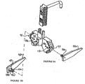
- Figures 5A and 5B illustrate a different implementation of the central body for achieving alignment with respect to the epicondylar axis and simultaneously providing medial and lateral femoral component positioning or size designations.
- the central body 90 of the component may be formed as a unit which, rather than being aligned by sighting slots 65 ( Figure 1), is provided with medial and lateral positioning bores 95, each of which accommodates a pointer arm that may be moved in and out along the axis of the bore on a mounting shaft 96a so that the tip of the arm 96b is aligned with the prominence of the corresponding epicondyle.
- the two arms thus position the body 90 parallel to the epicondylar axis.
- a cross pin 97 extends through each shaft 96a to ride in a corresponding horizontal slot 93 that extends across the bore 95, so that the arm extends in a fixed direction across the plane of the body and does not rotate about the shaft 96a. This assures that when the arms are visually aligned with the epicondylar prominences or centers, the body 90 is oriented along the epicondylar axis.
- a series of detente notches or sizing marks 98a... 98b on the shaft 96a indicate the position of the arm, and thus the offset to one or the other side of the body 90 when so positioned.
- the assembly may be flexibly positioned on the end face of the femur and allow an appropriate component size to be selected based upon each of the medial and lateral aspects of the bone ending.
- the body 90 slides on the A/P positioning assembly, and may be positioned with respect to the trochlear groove before determining the medial/lateral sizing.
- the surgeon is not required to first mark or scribe a line on the distal femoral resected surface 21.
- the pointer arms may be visually aligned with, or positioned close to or exactly on, the centers of the epicondyles to orient the tool guide body 90.
- an articulated caliper is configured to align on the opposed medial and lateral epicondylar centers while supporting the template in alignment at the bone surface 21.
- holes are drilled into the distal resected femur using the drill positioning guide holes 81a, 81b.
- the device is then removed, and the surgical procedure continues using standard A/P cutting blocks pinned in the two drill holes so made.
- the present invention advantageously provides a direct and positive positioning for a standard set of cutting blocks to achieve a fit compatible with the natural articulation geometry and to adjust that fit for proper patellar tracking. This results in a flexible preparation procedure, and permits several practical adjustments to be carried out with enhanced control or perception of the tensioning and positioning of necessary components.
Landscapes
- Health & Medical Sciences (AREA)
- Surgery (AREA)
- Life Sciences & Earth Sciences (AREA)
- Biomedical Technology (AREA)
- Medical Informatics (AREA)
- Oral & Maxillofacial Surgery (AREA)
- Nuclear Medicine, Radiotherapy & Molecular Imaging (AREA)
- Transplantation (AREA)
- Physical Education & Sports Medicine (AREA)
- Engineering & Computer Science (AREA)
- Orthopedic Medicine & Surgery (AREA)
- Heart & Thoracic Surgery (AREA)
- Dentistry (AREA)
- Molecular Biology (AREA)
- Animal Behavior & Ethology (AREA)
- General Health & Medical Sciences (AREA)
- Public Health (AREA)
- Veterinary Medicine (AREA)
- Surgical Instruments (AREA)
- Prostheses (AREA)
Claims (8)
- Structure (100) pour une utilisation dans la réalisation de coupes pour préparer un os (20) pour le montage d'un composant d'articulation prothétique ou similaire, une telle structure comprenant :caractérisée par ledit corps central (60) comprenant de plus un ensemble de visée (65) comprenant une fente ou fenêtre dans le corps central que l'on peut aligner avec une marque d'axe épicondylaire (25a, 25b) pour orienter le corps central (60) par rapport à l'axe épicondylaire de l'os, grâce à quoi l'ensemble de positionnement A/P (80) et l'ensemble de visée (65) permettent de régler simultanément la position du guide d'outil (61) par rapport au décalage A/P et à l'orientation axiale.un corps central (60) comprenant un guide d'outil (61) pour régler une position d'un outil pour couper un élément de détermination de position sur l'os, etun ensemble de positionnement A/P (80) comprenant un ensemble de crochet cortical (82, 84) pour régler une position A/P du corps central (60) contre l'os (20), le corps central (60) étant suspendu depuis ledit ensemble (80) pour un mouvement coulissant dans une position antéropostérieure,
- Structure (100) pour une utilisation dans la réalisation de coupes pour préparer un os (20) pour le montage d'un composant d'articulation prothétique ou similaire, une telle structure comprenant :caractérisée par ledit corps central (90) comprenant de plus un ensemble de visée (95, 96) comprenant un premier et un second bras (96) s'étendant depuis le corps central (90) et que l'on peut aligner sans engager les première et seconde régions épicondylaires opposées respectives de l'os et couplées au corps central (90) de telle façon que lorsqu'elles sont alignées avec lesdites régions, le corps central est orienté le long de l'axe épicondylaire de l'os pour orienter le corps central (90) par rapport audit axe épicondylaire, grâce à quoi l'ensemble de positionnement A/P (80) et l'ensemble de visée (95, 96) permettent à la position du guide d'outil (81) d'être réglée simultanément par rapport au décalage A/P et à l'orientation axiale.un corps central (90) comprenant un guide d'outil (81) pour régler une position d'un outil pour couper un élément de détermination de position sur l'os, etun ensemble de positionnement A/P (80) comprenant un ensemble de crochet cortical (82, 84) pour régler une position A/P du corps central (90) contre l'os (20), le corps central (90) étant suspendu depuis ledit ensemble (80) pour un mouvement coulissant dans une position antéropostérieure,
- Structure (100) selon la revendication 1 ou la revendication 2, dans lequel le corps central (60, 90) comprend un gabarit pour déterminer la taille de la prothèse pour l'os.
- Structure (100) selon la revendication 1, 2 ou 3, dans lequel l'ensemble de positionnement A/P (80) comprend un bras cortical (82) que l'on peut aligner le long de la gorge trochléaire en faisant glisser manuellement la position du corps central (60, 90) pour optimiser l'alignement patellaire tandis que l'on positionne le composant d'articulation prothétique.
- Structure (100) selon la revendication 4, dans lequel le corps central (60, 90) comprend un indicateur de taille (68a, 68b, 98a à 98d, 88) pour indiquer l'ajustement de la prothèse lorsque la structure (100) s'aligne simultanément par rapport à l'axe épicondylaire et à la gorge trochléaire.
- Structure selon l'une quelconque des revendications précédentes, dans laquelle l'os (20) est un fémur, la structure (100) comprenant de plus une jauge de contact A/P (84) pour indiquer un décalage A/P, et dans laquelle la structure (100) est mobile de façon manuelle le long de l'axe épicondylaire lorsque la jauge de contact (84) touche le fémur (20) pour adapter une position de prothèse pour améliorer le placement de la rotule.
- Structure selon l'une quelconque des revendications précédentes, dans laquelle le corps central (60, 90) comprend une projection de broches (61a, 61b) pour fixer de façon temporaire le corps central (60, 90) dans une position que l'on détermine de façon visuelle avant de couper l'élément de positionnement.
- Structure selon la revendication 1, dans laquelle le guide d'outil est un guide de perçage (61) pour positionner un ensemble de trous de perçage (61) dans une surface d'extrémité (21) de l'os (20) pour fixer un bloc de coupe.
Applications Claiming Priority (2)
| Application Number | Priority Date | Filing Date | Title |
|---|---|---|---|
| US09/216,043 US6106529A (en) | 1998-12-18 | 1998-12-18 | Epicondylar axis referencing drill guide |
| US216043 | 1998-12-18 |
Publications (3)
| Publication Number | Publication Date |
|---|---|
| EP1013232A2 EP1013232A2 (fr) | 2000-06-28 |
| EP1013232A3 EP1013232A3 (fr) | 2000-08-02 |
| EP1013232B1 true EP1013232B1 (fr) | 2005-10-26 |
Family
ID=22805447
Family Applications (1)
| Application Number | Title | Priority Date | Filing Date |
|---|---|---|---|
| EP99310229A Expired - Lifetime EP1013232B1 (fr) | 1998-12-18 | 1999-12-17 | Guide pour perceuse se repérant à l'axe épicondylaire |
Country Status (3)
| Country | Link |
|---|---|
| US (1) | US6106529A (fr) |
| EP (1) | EP1013232B1 (fr) |
| DE (1) | DE69927917T2 (fr) |
Cited By (9)
| Publication number | Priority date | Publication date | Assignee | Title |
|---|---|---|---|---|
| CN103732187A (zh) * | 2011-06-16 | 2014-04-16 | 捷迈有限公司 | 股骨假体系统 |
| US9301845B2 (en) | 2005-06-15 | 2016-04-05 | P Tech, Llc | Implant for knee replacement |
| US9308095B2 (en) | 2011-06-16 | 2016-04-12 | Zimmer, Inc. | Femoral component for a knee prosthesis with improved articular characteristics |
| US9629723B2 (en) | 2011-06-16 | 2017-04-25 | Zimmer, Inc. | Femoral component for a knee prosthesis with improved articular characteristics |
| US9867708B2 (en) | 2010-09-10 | 2018-01-16 | Zimmer Gmbh | Femoral prosthesis with lateralized patellar groove |
| US10070966B2 (en) | 2011-06-16 | 2018-09-11 | Zimmer, Inc. | Femoral component for a knee prosthesis with bone compacting ridge |
| US10130375B2 (en) | 2014-07-31 | 2018-11-20 | Zimmer, Inc. | Instruments and methods in performing kinematically-aligned total knee arthroplasty |
| US10136997B2 (en) | 2015-09-29 | 2018-11-27 | Zimmer, Inc. | Tibial prosthesis for tibia with varus resection |
| US10433966B2 (en) | 2005-12-15 | 2019-10-08 | Zimmer, Inc. | Distal femoral knee prostheses |
Families Citing this family (123)
| Publication number | Priority date | Publication date | Assignee | Title |
|---|---|---|---|---|
| US8083745B2 (en) | 2001-05-25 | 2011-12-27 | Conformis, Inc. | Surgical tools for arthroplasty |
| US7618451B2 (en) | 2001-05-25 | 2009-11-17 | Conformis, Inc. | Patient selectable joint arthroplasty devices and surgical tools facilitating increased accuracy, speed and simplicity in performing total and partial joint arthroplasty |
| US7534263B2 (en) | 2001-05-25 | 2009-05-19 | Conformis, Inc. | Surgical tools facilitating increased accuracy, speed and simplicity in performing joint arthroplasty |
| US7468075B2 (en) | 2001-05-25 | 2008-12-23 | Conformis, Inc. | Methods and compositions for articular repair |
| CA2201800C (fr) * | 1997-04-04 | 2003-01-28 | Brian Kelly | Methode et appareil de localisation d'une droite transepicondylienne dans une articulation qui permet de definir l'action transversale pour un mouvement |
| US6045551A (en) | 1998-02-06 | 2000-04-04 | Bonutti; Peter M. | Bone suture |
| JP2002532126A (ja) | 1998-09-14 | 2002-10-02 | スタンフォード ユニバーシティ | 関節状態の評価及び損傷防止装置 |
| US7239908B1 (en) | 1998-09-14 | 2007-07-03 | The Board Of Trustees Of The Leland Stanford Junior University | Assessing the condition of a joint and devising treatment |
| DE29906909U1 (de) * | 1999-03-02 | 1999-09-30 | Plus Endoprothetik Ag, Rotkreuz | Femurschlitten |
| US6368343B1 (en) | 2000-03-13 | 2002-04-09 | Peter M. Bonutti | Method of using ultrasonic vibration to secure body tissue |
| US6447516B1 (en) | 1999-08-09 | 2002-09-10 | Peter M. Bonutti | Method of securing tissue |
| US7635390B1 (en) | 2000-01-14 | 2009-12-22 | Marctec, Llc | Joint replacement component having a modular articulating surface |
| US6635073B2 (en) | 2000-05-03 | 2003-10-21 | Peter M. Bonutti | Method of securing body tissue |
| US6702821B2 (en) * | 2000-01-14 | 2004-03-09 | The Bonutti 2003 Trust A | Instrumentation for minimally invasive joint replacement and methods for using same |
| EP1322225B1 (fr) | 2000-09-14 | 2009-03-25 | The Board Of Trustees Of The Leland Stanford Junior University | Evaluation de l'etat d'une articulation et traitement afferent |
| AU2001290887B2 (en) | 2000-09-14 | 2006-06-08 | The Board Of Trustees Of The Leland Stanford Junior University | Assessing condition of a joint and cartilage loss |
| EP1389980B1 (fr) | 2001-05-25 | 2011-04-06 | Conformis, Inc. | Methodes et compositions d'arthroplastie |
| US8439926B2 (en) | 2001-05-25 | 2013-05-14 | Conformis, Inc. | Patient selectable joint arthroplasty devices and surgical tools |
| US6482209B1 (en) | 2001-06-14 | 2002-11-19 | Gerard A. Engh | Apparatus and method for sculpting the surface of a joint |
| US6723102B2 (en) * | 2001-06-14 | 2004-04-20 | Alexandria Research Technologies, Llc | Apparatus and method for minimally invasive total joint replacement |
| US7708741B1 (en) | 2001-08-28 | 2010-05-04 | Marctec, Llc | Method of preparing bones for knee replacement surgery |
| US6719765B2 (en) | 2001-12-03 | 2004-04-13 | Bonutti 2003 Trust-A | Magnetic suturing system and method |
| US8801720B2 (en) * | 2002-05-15 | 2014-08-12 | Otismed Corporation | Total joint arthroplasty system |
| US20030236522A1 (en) | 2002-06-21 | 2003-12-25 | Jack Long | Prosthesis cavity cutting guide, cutting tool and method |
| US8211113B2 (en) | 2002-06-21 | 2012-07-03 | Depuy Products, Inc. | Prosthesis cutting guide, cutting tool and method |
| US7935118B2 (en) | 2002-06-21 | 2011-05-03 | Depuy Products, Inc. | Prosthesis removal cutting guide, cutting tool and method |
| AU2003287190A1 (en) | 2002-10-23 | 2004-05-13 | Alastair J. T. Clemow | Modular femoral component for a total knee joint replacement for minimally invasive implantation |
| US7887542B2 (en) | 2003-01-15 | 2011-02-15 | Biomet Manufacturing Corp. | Method and apparatus for less invasive knee resection |
| US8551100B2 (en) | 2003-01-15 | 2013-10-08 | Biomet Manufacturing, Llc | Instrumentation for knee resection |
| US7837690B2 (en) | 2003-01-15 | 2010-11-23 | Biomet Manufacturing Corp. | Method and apparatus for less invasive knee resection |
| US7789885B2 (en) | 2003-01-15 | 2010-09-07 | Biomet Manufacturing Corp. | Instrumentation for knee resection |
| US7175630B2 (en) * | 2003-02-03 | 2007-02-13 | Zimmer Technology, Inc. | Bone cutting template and method of use |
| US7488324B1 (en) | 2003-12-08 | 2009-02-10 | Biomet Manufacturing Corporation | Femoral guide for implanting a femoral knee prosthesis |
| US20050187560A1 (en) * | 2004-01-29 | 2005-08-25 | Dietzel Steven E. | Apparatus and method for sizing a distal femur |
| US8114086B2 (en) | 2004-03-08 | 2012-02-14 | Zimmer Technology, Inc. | Navigated cut guide locator |
| US7993341B2 (en) | 2004-03-08 | 2011-08-09 | Zimmer Technology, Inc. | Navigated orthopaedic guide and method |
| US7507242B2 (en) * | 2004-06-02 | 2009-03-24 | Facet Solutions | Surgical measurement and resection framework |
| WO2006069336A1 (fr) * | 2004-12-21 | 2006-06-29 | Smith & Nephew, Inc. | Guide de calibrage du femur pour son alignement rotatoire |
| US20060195116A1 (en) * | 2005-02-25 | 2006-08-31 | Fox Michael D | D-Tail patellar bone tunneling system |
| US20060195108A1 (en) * | 2005-02-25 | 2006-08-31 | Fox Michael D | Patellar bone tunneling system |
| US7628794B2 (en) * | 2005-04-06 | 2009-12-08 | Trigon Inc. | Prosthetic revision knee system |
| US7695479B1 (en) | 2005-04-12 | 2010-04-13 | Biomet Manufacturing Corp. | Femoral sizer |
| US7520880B2 (en) | 2006-01-09 | 2009-04-21 | Zimmer Technology, Inc. | Adjustable surgical support base with integral hinge |
| US7744600B2 (en) | 2006-01-10 | 2010-06-29 | Zimmer Technology, Inc. | Bone resection guide and method |
| US8740910B2 (en) * | 2006-01-12 | 2014-06-03 | Howmedica Osteonics Corp. | Modular anterior-posterior femoral sizer |
| JP5128497B2 (ja) | 2006-01-23 | 2013-01-23 | スミス アンド ネフュー インコーポレーテッド | 膝蓋構成要素 |
| EP2649951A3 (fr) | 2006-02-06 | 2013-12-25 | ConforMIS, Inc. | Dispositifs d'arthroplastie articulaire et outils chirurgicaux selectionnables par le patient |
| US8623026B2 (en) | 2006-02-06 | 2014-01-07 | Conformis, Inc. | Patient selectable joint arthroplasty devices and surgical tools incorporating anatomical relief |
| CA2642615A1 (fr) | 2006-02-15 | 2007-08-30 | Otismed Corp | Dispositifs d'arthroplastie et procedes correspondants |
| US9808262B2 (en) | 2006-02-15 | 2017-11-07 | Howmedica Osteonics Corporation | Arthroplasty devices and related methods |
| US10278711B2 (en) | 2006-02-27 | 2019-05-07 | Biomet Manufacturing, Llc | Patient-specific femoral guide |
| US9907659B2 (en) | 2007-04-17 | 2018-03-06 | Biomet Manufacturing, Llc | Method and apparatus for manufacturing an implant |
| US7780672B2 (en) | 2006-02-27 | 2010-08-24 | Biomet Manufacturing Corp. | Femoral adjustment device and associated method |
| US8603180B2 (en) | 2006-02-27 | 2013-12-10 | Biomet Manufacturing, Llc | Patient-specific acetabular alignment guides |
| US9345548B2 (en) | 2006-02-27 | 2016-05-24 | Biomet Manufacturing, Llc | Patient-specific pre-operative planning |
| US9339278B2 (en) | 2006-02-27 | 2016-05-17 | Biomet Manufacturing, Llc | Patient-specific acetabular guides and associated instruments |
| US9289253B2 (en) | 2006-02-27 | 2016-03-22 | Biomet Manufacturing, Llc | Patient-specific shoulder guide |
| US8407067B2 (en) | 2007-04-17 | 2013-03-26 | Biomet Manufacturing Corp. | Method and apparatus for manufacturing an implant |
| US20150335438A1 (en) | 2006-02-27 | 2015-11-26 | Biomet Manufacturing, Llc. | Patient-specific augments |
| US8591516B2 (en) | 2006-02-27 | 2013-11-26 | Biomet Manufacturing, Llc | Patient-specific orthopedic instruments |
| US9918740B2 (en) | 2006-02-27 | 2018-03-20 | Biomet Manufacturing, Llc | Backup surgical instrument system and method |
| US9173661B2 (en) | 2006-02-27 | 2015-11-03 | Biomet Manufacturing, Llc | Patient specific alignment guide with cutting surface and laser indicator |
| US9113971B2 (en) | 2006-02-27 | 2015-08-25 | Biomet Manufacturing, Llc | Femoral acetabular impingement guide |
| US8070752B2 (en) | 2006-02-27 | 2011-12-06 | Biomet Manufacturing Corp. | Patient specific alignment guide and inter-operative adjustment |
| US9795399B2 (en) | 2006-06-09 | 2017-10-24 | Biomet Manufacturing, Llc | Patient-specific knee alignment guide and associated method |
| US7828752B2 (en) * | 2006-10-05 | 2010-11-09 | Arthroplasty Innovations, Llc | Device and method for locating the anteroposterior femoral axis to determine proper femoral component rotation in knee replacement |
| EP1958575B1 (fr) * | 2007-02-13 | 2014-08-13 | Brainlab AG | Dispositif ou système de positionnement ou de préparation du positionnement d'un instrument d'opération chirurgicale, spécialement un bloc d'incision ou un bloc de coupe ou un dispositif de d'équilibrage ligamentaire |
| GB2447702A (en) | 2007-03-23 | 2008-09-24 | Univ Leeds | Surgical bone cutting template |
| US8764841B2 (en) * | 2007-03-30 | 2014-07-01 | DePuy Synthes Products, LLC | Mobile bearing assembly having a closed track |
| US8147558B2 (en) * | 2007-03-30 | 2012-04-03 | Depuy Products, Inc. | Mobile bearing assembly having multiple articulation interfaces |
| US8142510B2 (en) * | 2007-03-30 | 2012-03-27 | Depuy Products, Inc. | Mobile bearing assembly having a non-planar interface |
| US8147557B2 (en) * | 2007-03-30 | 2012-04-03 | Depuy Products, Inc. | Mobile bearing insert having offset dwell point |
| US8328874B2 (en) * | 2007-03-30 | 2012-12-11 | Depuy Products, Inc. | Mobile bearing assembly |
| US7985226B2 (en) * | 2007-05-04 | 2011-07-26 | Mcallister Craig M | Distal femoral cutting guide |
| WO2008157412A2 (fr) | 2007-06-13 | 2008-12-24 | Conformis, Inc. | Guide d'incision chirurgical |
| US8265949B2 (en) | 2007-09-27 | 2012-09-11 | Depuy Products, Inc. | Customized patient surgical plan |
| US8357111B2 (en) | 2007-09-30 | 2013-01-22 | Depuy Products, Inc. | Method and system for designing patient-specific orthopaedic surgical instruments |
| US8398645B2 (en) | 2007-09-30 | 2013-03-19 | DePuy Synthes Products, LLC | Femoral tibial customized patient-specific orthopaedic surgical instrumentation |
| US8460303B2 (en) | 2007-10-25 | 2013-06-11 | Otismed Corporation | Arthroplasty systems and devices, and related methods |
| USD642263S1 (en) | 2007-10-25 | 2011-07-26 | Otismed Corporation | Arthroplasty jig blank |
| US10582934B2 (en) | 2007-11-27 | 2020-03-10 | Howmedica Osteonics Corporation | Generating MRI images usable for the creation of 3D bone models employed to make customized arthroplasty jigs |
| US8715291B2 (en) | 2007-12-18 | 2014-05-06 | Otismed Corporation | Arthroplasty system and related methods |
| US8311306B2 (en) | 2008-04-30 | 2012-11-13 | Otismed Corporation | System and method for image segmentation in generating computer models of a joint to undergo arthroplasty |
| US8480679B2 (en) * | 2008-04-29 | 2013-07-09 | Otismed Corporation | Generation of a computerized bone model representative of a pre-degenerated state and useable in the design and manufacture of arthroplasty devices |
| US8545509B2 (en) | 2007-12-18 | 2013-10-01 | Otismed Corporation | Arthroplasty system and related methods |
| US8221430B2 (en) | 2007-12-18 | 2012-07-17 | Otismed Corporation | System and method for manufacturing arthroplasty jigs |
| US8737700B2 (en) | 2007-12-18 | 2014-05-27 | Otismed Corporation | Preoperatively planning an arthroplasty procedure and generating a corresponding patient specific arthroplasty resection guide |
| US8617171B2 (en) | 2007-12-18 | 2013-12-31 | Otismed Corporation | Preoperatively planning an arthroplasty procedure and generating a corresponding patient specific arthroplasty resection guide |
| US8160345B2 (en) | 2008-04-30 | 2012-04-17 | Otismed Corporation | System and method for image segmentation in generating computer models of a joint to undergo arthroplasty |
| US8777875B2 (en) | 2008-07-23 | 2014-07-15 | Otismed Corporation | System and method for manufacturing arthroplasty jigs having improved mating accuracy |
| US8734455B2 (en) | 2008-02-29 | 2014-05-27 | Otismed Corporation | Hip resurfacing surgical guide tool |
| US8617175B2 (en) | 2008-12-16 | 2013-12-31 | Otismed Corporation | Unicompartmental customized arthroplasty cutting jigs and methods of making the same |
| JP5302595B2 (ja) * | 2008-08-06 | 2013-10-02 | 株式会社日立ハイテクノロジーズ | 傾斜観察方法および観察装置 |
| US9017334B2 (en) | 2009-02-24 | 2015-04-28 | Microport Orthopedics Holdings Inc. | Patient specific surgical guide locator and mount |
| US8808297B2 (en) | 2009-02-24 | 2014-08-19 | Microport Orthopedics Holdings Inc. | Orthopedic surgical guide |
| US12383287B2 (en) | 2009-02-24 | 2025-08-12 | Microport Orthopedics Holdings, Inc. | Systems and methods for installing an orthopedic implant |
| US8808303B2 (en) | 2009-02-24 | 2014-08-19 | Microport Orthopedics Holdings Inc. | Orthopedic surgical guide |
| BRPI1014917A2 (pt) | 2009-04-16 | 2016-04-19 | Conformis Inc | "dispositivos de artroplastia de junta específica para páciente para reparo de ligamento" |
| GB201006716D0 (en) * | 2010-04-22 | 2010-06-09 | Depuy Ireland | A composite trial prosthesis |
| US8974459B1 (en) | 2010-05-21 | 2015-03-10 | Howmedica Osteonics Corp. | Natural alignment knee instruments |
| US9968376B2 (en) | 2010-11-29 | 2018-05-15 | Biomet Manufacturing, Llc | Patient-specific orthopedic instruments |
| US9241745B2 (en) | 2011-03-07 | 2016-01-26 | Biomet Manufacturing, Llc | Patient-specific femoral version guide |
| US8870884B2 (en) | 2011-06-27 | 2014-10-28 | Biomet Sports Medicine, Llc | Method for repairing bone defects |
| US8728084B2 (en) | 2011-06-27 | 2014-05-20 | Biomet Sports Medicine, Llc | Apparatus for repairing bone defects |
| US8968412B2 (en) | 2011-06-30 | 2015-03-03 | Depuy (Ireland) | Trialing system for a knee prosthesis and method of use |
| US9486226B2 (en) | 2012-04-18 | 2016-11-08 | Conformis, Inc. | Tibial guides, tools, and techniques for resecting the tibial plateau |
| US9675471B2 (en) | 2012-06-11 | 2017-06-13 | Conformis, Inc. | Devices, techniques and methods for assessing joint spacing, balancing soft tissues and obtaining desired kinematics for joint implant components |
| US9033902B2 (en) | 2012-08-29 | 2015-05-19 | Howmedica Osteonics Corp. | Femoral condylar radius gage |
| US9402637B2 (en) | 2012-10-11 | 2016-08-02 | Howmedica Osteonics Corporation | Customized arthroplasty cutting guides and surgical methods using the same |
| US9861491B2 (en) | 2014-04-30 | 2018-01-09 | Depuy Ireland Unlimited Company | Tibial trial system for a knee prosthesis |
| US10575968B2 (en) | 2014-05-16 | 2020-03-03 | Howmedica Osteonics Corp. | Guides for fracture system |
| US9681960B2 (en) * | 2014-05-16 | 2017-06-20 | Howmedica Osteonics Corp. | Guides for fracture system |
| US10537445B2 (en) | 2015-10-19 | 2020-01-21 | Depuy Ireland Unlimited Company | Surgical instruments for preparing a patient's tibia to receive an implant |
| US10195056B2 (en) | 2015-10-19 | 2019-02-05 | Depuy Ireland Unlimited Company | Method for preparing a patient's tibia to receive an implant |
| CN106063705A (zh) * | 2016-07-28 | 2016-11-02 | 常州奥斯迈医疗器械有限公司 | 股骨髁ap测量器 |
| US10722310B2 (en) | 2017-03-13 | 2020-07-28 | Zimmer Biomet CMF and Thoracic, LLC | Virtual surgery planning system and method |
| US11051829B2 (en) | 2018-06-26 | 2021-07-06 | DePuy Synthes Products, Inc. | Customized patient-specific orthopaedic surgical instrument |
| AU2020283377B2 (en) | 2019-05-29 | 2022-08-04 | Wright Medical Technology, Inc. | Preparing a tibia for receiving tibial implant component of a replacement ankle |
| WO2021146015A1 (fr) | 2020-01-17 | 2021-07-22 | Wright Medical Technology, Inc. | Outils, systèmes et procédés de guidage |
| CN112998806B (zh) * | 2020-12-11 | 2022-07-12 | 慈铭博鳌国际医院有限公司 | 一种智能医疗辅助手术平台 |
| US12440227B2 (en) | 2021-02-24 | 2025-10-14 | Wright Medical Technology, Inc. | Preparing a tibia for receiving tibial implant component of a replacement ankle |
| US12582421B2 (en) | 2022-05-13 | 2026-03-24 | Wright Medical Technology, Inc. | Intraoperative adjustable guides, systems, and methods |
| US12569355B2 (en) | 2023-08-31 | 2026-03-10 | Wright Medical Technology, Inc. | Systems and methods for total ankle arthroplasty |
Family Cites Families (13)
| Publication number | Priority date | Publication date | Assignee | Title |
|---|---|---|---|---|
| US4524766A (en) * | 1982-01-07 | 1985-06-25 | Petersen Thomas D | Surgical knee alignment method and system |
| US4759350A (en) * | 1986-10-17 | 1988-07-26 | Dunn Harold K | Instruments for shaping distal femoral and proximal tibial surfaces |
| US5258032A (en) * | 1992-04-03 | 1993-11-02 | Bertin Kim C | Knee prosthesis provisional apparatus and resection guide and method of use in knee replacement surgery |
| US5445642A (en) * | 1992-09-01 | 1995-08-29 | Depuy Inc. | Method for installing a femoral component |
| US5474559A (en) * | 1993-07-06 | 1995-12-12 | Zimmer, Inc. | Femoral milling instrumentation for use in total knee arthroplasty with optional cutting guide attachment |
| US5443518A (en) * | 1993-07-20 | 1995-08-22 | Zimmer, Inc. | Knee position indicator |
| US5395377A (en) * | 1993-09-21 | 1995-03-07 | Petersen; Thomas D. | Extramedullary proximal tibial guide |
| US5417694A (en) * | 1993-11-08 | 1995-05-23 | Smith & Nephew Richards Inc. | Distal femoral cutting guide apparatus with anterior or posterior referencing for use in knee joint replacement surgery |
| US5810831A (en) * | 1994-02-16 | 1998-09-22 | Osteonics Corp. | Femoral sizing guide and method |
| USD367706S (en) | 1994-05-09 | 1996-03-05 | Zimmer, Inc. | Alignment guide for an orthopaedic bone cutting guide |
| US5423827A (en) * | 1994-06-02 | 1995-06-13 | Intermedics Orthopedics, Inc. | Surgical jig for femoral knee prosthesis |
| US5540696A (en) * | 1995-01-06 | 1996-07-30 | Zimmer, Inc. | Instrumentation for use in orthopaedic surgery |
| US5830216A (en) * | 1996-10-30 | 1998-11-03 | Bristol-Myers Squibb Company | Apparatus and method for knee implantation |
-
1998
- 1998-12-18 US US09/216,043 patent/US6106529A/en not_active Expired - Lifetime
-
1999
- 1999-12-17 DE DE69927917T patent/DE69927917T2/de not_active Expired - Lifetime
- 1999-12-17 EP EP99310229A patent/EP1013232B1/fr not_active Expired - Lifetime
Cited By (20)
| Publication number | Priority date | Publication date | Assignee | Title |
|---|---|---|---|---|
| US9301845B2 (en) | 2005-06-15 | 2016-04-05 | P Tech, Llc | Implant for knee replacement |
| US10433966B2 (en) | 2005-12-15 | 2019-10-08 | Zimmer, Inc. | Distal femoral knee prostheses |
| US9867708B2 (en) | 2010-09-10 | 2018-01-16 | Zimmer Gmbh | Femoral prosthesis with lateralized patellar groove |
| US10322004B2 (en) | 2010-09-10 | 2019-06-18 | Zimmer Gmbh | Femoral prosthesis with lateralized patellar groove |
| US9993345B2 (en) | 2011-06-16 | 2018-06-12 | Zimmer, Inc. | Femoral prosthesis system |
| US9629723B2 (en) | 2011-06-16 | 2017-04-25 | Zimmer, Inc. | Femoral component for a knee prosthesis with improved articular characteristics |
| CN103732187A (zh) * | 2011-06-16 | 2014-04-16 | 捷迈有限公司 | 股骨假体系统 |
| US10045850B2 (en) | 2011-06-16 | 2018-08-14 | Zimmer, Inc. | Femoral component for a knee prosthesis with improved articular characteristics |
| US10070966B2 (en) | 2011-06-16 | 2018-09-11 | Zimmer, Inc. | Femoral component for a knee prosthesis with bone compacting ridge |
| US12213889B2 (en) | 2011-06-16 | 2025-02-04 | Zimmer, Inc. | Femoral component for a knee prosthesis with improved articular characteristics |
| US12048630B2 (en) | 2011-06-16 | 2024-07-30 | Zimmer, Inc. | Femoral component for a knee prosthesis with improved articular characteristics |
| US9308095B2 (en) | 2011-06-16 | 2016-04-12 | Zimmer, Inc. | Femoral component for a knee prosthesis with improved articular characteristics |
| CN103732187B (zh) * | 2011-06-16 | 2015-12-02 | 捷迈有限公司 | 股骨假体系统 |
| US10441429B2 (en) | 2011-06-16 | 2019-10-15 | Zimmer, Inc. | Femoral component for a knee prosthesis with improved articular characteristics |
| US11246710B2 (en) | 2011-06-16 | 2022-02-15 | Zimmer, Inc. | Femoral component for a knee prosthesis with improved articular characteristics |
| US10939923B2 (en) | 2014-07-31 | 2021-03-09 | Zimmer, Inc. | Instruments and methods in performing kinematically-aligned total knee arthroplasty |
| US10130375B2 (en) | 2014-07-31 | 2018-11-20 | Zimmer, Inc. | Instruments and methods in performing kinematically-aligned total knee arthroplasty |
| US10631991B2 (en) | 2015-09-29 | 2020-04-28 | Zimmer, Inc. | Tibial prosthesis for tibia with varus resection |
| US11491018B2 (en) | 2015-09-29 | 2022-11-08 | Zimmer, Inc. | Tibial prosthesis for tibia with varus resection |
| US10136997B2 (en) | 2015-09-29 | 2018-11-27 | Zimmer, Inc. | Tibial prosthesis for tibia with varus resection |
Also Published As
| Publication number | Publication date |
|---|---|
| EP1013232A2 (fr) | 2000-06-28 |
| DE69927917D1 (de) | 2005-12-01 |
| DE69927917T2 (de) | 2006-07-20 |
| EP1013232A3 (fr) | 2000-08-02 |
| US6106529A (en) | 2000-08-22 |
Similar Documents
| Publication | Publication Date | Title |
|---|---|---|
| EP1013232B1 (fr) | Guide pour perceuse se repérant à l'axe épicondylaire | |
| US6096043A (en) | Epicondylar axis alignment-femoral positioning drill guide | |
| EP0979636B1 (fr) | Dispositif pour tendre les ligaments du fémur et pour déterminer la taille d'une prothèse | |
| EP1827254B1 (fr) | Guide de calibrage du femur pour son alignement rotatoire | |
| US6458135B1 (en) | Femoral guide for implanting a femoral knee prosthesis and method | |
| US5830216A (en) | Apparatus and method for knee implantation | |
| CN107252338B (zh) | 用于执行膝关节成形术的方法和器械 | |
| US6013081A (en) | Apparatus and method for anterior and posterior referenced sizing and distal femur resection | |
| US5624444A (en) | Femoral resection instrumentation including three-dimensional jig and method of use | |
| EP2953559B1 (fr) | Systèmes d'arthroplastie totale du genou | |
| US5720752A (en) | Distal femoral cutting guide apparatus with anterior or posterior referencing for use in knee joint replacement surgery | |
| US20030187452A1 (en) | Instruments and methods for flexion gap adjustment | |
| WO1997030640A9 (fr) | Instrument de section femorale a guidage distal | |
| US11033281B2 (en) | Knee resection and gap balancing instruments and techniques for kinematic alignment | |
| EP2896375A1 (fr) | Guide-foret | |
| AU4654993A (en) | Sizing and cutting guide for resecting the distal end of the femur | |
| US7175630B2 (en) | Bone cutting template and method of use | |
| CN108348263A (zh) | 用于关节成形术规划的可调节的切割块及尺寸确定器械 | |
| AU2014268275A1 (en) | A Drill Guide |
Legal Events
| Date | Code | Title | Description |
|---|---|---|---|
| PUAI | Public reference made under article 153(3) epc to a published international application that has entered the european phase |
Free format text: ORIGINAL CODE: 0009012 |
|
| PUAL | Search report despatched |
Free format text: ORIGINAL CODE: 0009013 |
|
| AK | Designated contracting states |
Kind code of ref document: A2 Designated state(s): CH DE FR GB LI |
|
| AX | Request for extension of the european patent |
Free format text: AL;LT;LV;MK;RO;SI |
|
| AK | Designated contracting states |
Kind code of ref document: A3 Designated state(s): AT BE CH CY DE DK ES FI FR GB GR IE IT LI LU MC NL PT SE |
|
| AX | Request for extension of the european patent |
Free format text: AL;LT;LV;MK;RO;SI |
|
| 17P | Request for examination filed |
Effective date: 20010105 |
|
| AKX | Designation fees paid |
Free format text: CH DE FR GB LI |
|
| RAP1 | Party data changed (applicant data changed or rights of an application transferred) |
Owner name: DEPUY PRODUCTS, INC. |
|
| RAP1 | Party data changed (applicant data changed or rights of an application transferred) |
Owner name: DEPUY PRODUCTS, INC. |
|
| 17Q | First examination report despatched |
Effective date: 20031202 |
|
| GRAP | Despatch of communication of intention to grant a patent |
Free format text: ORIGINAL CODE: EPIDOSNIGR1 |
|
| GRAS | Grant fee paid |
Free format text: ORIGINAL CODE: EPIDOSNIGR3 |
|
| GRAA | (expected) grant |
Free format text: ORIGINAL CODE: 0009210 |
|
| AK | Designated contracting states |
Kind code of ref document: B1 Designated state(s): CH DE FR GB LI |
|
| REG | Reference to a national code |
Ref country code: GB Ref legal event code: FG4D |
|
| REG | Reference to a national code |
Ref country code: CH Ref legal event code: EP |
|
| REF | Corresponds to: |
Ref document number: 69927917 Country of ref document: DE Date of ref document: 20051201 Kind code of ref document: P |
|
| REG | Reference to a national code |
Ref country code: CH Ref legal event code: NV Representative=s name: E. BLUM & CO. PATENTANWAELTE |
|
| ET | Fr: translation filed | ||
| PLBE | No opposition filed within time limit |
Free format text: ORIGINAL CODE: 0009261 |
|
| STAA | Information on the status of an ep patent application or granted ep patent |
Free format text: STATUS: NO OPPOSITION FILED WITHIN TIME LIMIT |
|
| 26N | No opposition filed |
Effective date: 20060727 |
|
| REG | Reference to a national code |
Ref country code: CH Ref legal event code: PFA Owner name: DEPUY PRODUCTS, INC. Free format text: DEPUY PRODUCTS, INC.#700 ORTHOPAEDIC DRIVE#WARSAW, IN 46581 (US) -TRANSFER TO- DEPUY PRODUCTS, INC.#700 ORTHOPAEDIC DRIVE#WARSAW, IN 46581 (US) |
|
| PGFP | Annual fee paid to national office [announced via postgrant information from national office to epo] |
Ref country code: DE Payment date: 20131211 Year of fee payment: 15 Ref country code: GB Payment date: 20131211 Year of fee payment: 15 Ref country code: CH Payment date: 20131212 Year of fee payment: 15 |
|
| PGFP | Annual fee paid to national office [announced via postgrant information from national office to epo] |
Ref country code: FR Payment date: 20131209 Year of fee payment: 15 |
|
| REG | Reference to a national code |
Ref country code: DE Ref legal event code: R119 Ref document number: 69927917 Country of ref document: DE |
|
| REG | Reference to a national code |
Ref country code: CH Ref legal event code: PL |
|
| GBPC | Gb: european patent ceased through non-payment of renewal fee |
Effective date: 20141217 |
|
| REG | Reference to a national code |
Ref country code: FR Ref legal event code: ST Effective date: 20150831 |
|
| PG25 | Lapsed in a contracting state [announced via postgrant information from national office to epo] |
Ref country code: GB Free format text: LAPSE BECAUSE OF NON-PAYMENT OF DUE FEES Effective date: 20141217 Ref country code: DE Free format text: LAPSE BECAUSE OF NON-PAYMENT OF DUE FEES Effective date: 20150701 Ref country code: LI Free format text: LAPSE BECAUSE OF NON-PAYMENT OF DUE FEES Effective date: 20141231 Ref country code: CH Free format text: LAPSE BECAUSE OF NON-PAYMENT OF DUE FEES Effective date: 20141231 |
|
| PG25 | Lapsed in a contracting state [announced via postgrant information from national office to epo] |
Ref country code: FR Free format text: LAPSE BECAUSE OF NON-PAYMENT OF DUE FEES Effective date: 20141231 |