EP1013346A1 - Halterung für eine Fluidpistole - Google Patents
Halterung für eine Fluidpistole Download PDFInfo
- Publication number
- EP1013346A1 EP1013346A1 EP99122938A EP99122938A EP1013346A1 EP 1013346 A1 EP1013346 A1 EP 1013346A1 EP 99122938 A EP99122938 A EP 99122938A EP 99122938 A EP99122938 A EP 99122938A EP 1013346 A1 EP1013346 A1 EP 1013346A1
- Authority
- EP
- European Patent Office
- Prior art keywords
- gun
- free
- recess
- wall section
- wall
- Prior art date
- Legal status (The legal status is an assumption and is not a legal conclusion. Google has not performed a legal analysis and makes no representation as to the accuracy of the status listed.)
- Granted
Links
- 239000012530 fluid Substances 0.000 title claims description 20
- 230000005484 gravity Effects 0.000 claims abstract description 10
- 125000006850 spacer group Chemical group 0.000 claims description 6
- 238000012549 training Methods 0.000 claims description 6
- 239000007921 spray Substances 0.000 description 15
- 230000001681 protective effect Effects 0.000 description 8
- 230000008901 benefit Effects 0.000 description 5
- 238000007373 indentation Methods 0.000 description 3
- 238000004519 manufacturing process Methods 0.000 description 3
- XEEYBQQBJWHFJM-UHFFFAOYSA-N Iron Chemical compound [Fe] XEEYBQQBJWHFJM-UHFFFAOYSA-N 0.000 description 2
- 238000013459 approach Methods 0.000 description 2
- 238000010276 construction Methods 0.000 description 2
- 238000013461 design Methods 0.000 description 2
- 210000003128 head Anatomy 0.000 description 2
- 239000003973 paint Substances 0.000 description 2
- 239000002689 soil Substances 0.000 description 2
- 230000004888 barrier function Effects 0.000 description 1
- 230000015572 biosynthetic process Effects 0.000 description 1
- 230000008859 change Effects 0.000 description 1
- 239000003795 chemical substances by application Substances 0.000 description 1
- 230000000295 complement effect Effects 0.000 description 1
- 230000008878 coupling Effects 0.000 description 1
- 238000010168 coupling process Methods 0.000 description 1
- 238000005859 coupling reaction Methods 0.000 description 1
- 230000006735 deficit Effects 0.000 description 1
- 230000001419 dependent effect Effects 0.000 description 1
- 230000000694 effects Effects 0.000 description 1
- 230000002349 favourable effect Effects 0.000 description 1
- 210000001061 forehead Anatomy 0.000 description 1
- 230000006698 induction Effects 0.000 description 1
- 238000001746 injection moulding Methods 0.000 description 1
- 238000003780 insertion Methods 0.000 description 1
- 230000037431 insertion Effects 0.000 description 1
- 229910052742 iron Inorganic materials 0.000 description 1
- 238000003754 machining Methods 0.000 description 1
- 239000002184 metal Substances 0.000 description 1
- 229910052751 metal Inorganic materials 0.000 description 1
- 238000005555 metalworking Methods 0.000 description 1
- 230000004048 modification Effects 0.000 description 1
- 238000012986 modification Methods 0.000 description 1
- 230000002093 peripheral effect Effects 0.000 description 1
- 238000003825 pressing Methods 0.000 description 1
- 239000011435 rock Substances 0.000 description 1
- 238000005507 spraying Methods 0.000 description 1
- 230000003068 static effect Effects 0.000 description 1
- 239000000725 suspension Substances 0.000 description 1
- 238000012360 testing method Methods 0.000 description 1
- 230000007704 transition Effects 0.000 description 1
- 210000001364 upper extremity Anatomy 0.000 description 1
Images


Classifications
-
- B—PERFORMING OPERATIONS; TRANSPORTING
- B05—SPRAYING OR ATOMISING IN GENERAL; APPLYING FLUENT MATERIALS TO SURFACES, IN GENERAL
- B05B—SPRAYING APPARATUS; ATOMISING APPARATUS; NOZZLES
- B05B15/00—Details of spraying plant or spraying apparatus not otherwise provided for; Accessories
- B05B15/60—Arrangements for mounting, supporting or holding spraying apparatus
- B05B15/62—Arrangements for supporting spraying apparatus, e.g. suction cups
Definitions
- the invention relates to an arrangement for holding a fluid, in particular Compressed air gun on a vertical wall or other surface, with a protruding bracket attached to it, which holds the pistol has a receiving device, the pistol having a complementary one Holding element is provided.
- the invention further relates to a for this arrangement created bracket body, the at least one free or Recess within its outside or a section of its outer surface having.
- the invention relates to a fluid, in particular compressed air gun, which is prepared for mounting in the arrangement mentioned.
- the Compressed air pistols In manufacturing plants and production halls, especially the metalworking Compressed air guns are used in industry to blow metal chips away, that have arisen during the machining of workpieces. To do this, the Compressed air pistols have a mounting or hanging space in which they can be used for working people are within reach. In many cases the unwanted one prevails Practice before, the pistols on their pressure lever on suitable edges or edges the machine tools or the like. The swiveling serving the linkage of the pistol pressure lever is worn out and loses stability. The swivel lever guide is becoming increasingly unstable and shaky, until soon the compressed air pistol has to be replaced by a new one.
- a mounting arrangement of the aforementioned is kind known in which the pistol as a holding element on the crest of its barrel trained trained eyelet.
- the gun can be attached to this using a hook hang up as a support body in the wall or other surface protruding is attached.
- the "threading" of the hook through the Cumbersome to handle.
- the pistol in hand must be always be rotated by 90 ° for hanging because the well-known bracket eyelet in is formed lying in a longitudinal plane of the gun barrel. This turning contradicts ergonomic requirements. Brackets protruding from walls bring with them the danger that the working people get involved bump and hurt him.
- a hollow, about tubular head part has a longitudinal groove, in which one of one Have the outgoing pistol shaft inserted.
- To its axial Fixing are at two opposite points of the groove walls Milled recesses in the two projections (screw heads) on the left and can slide in on the right of the pistol shaft so that the pistol Moving and twisting is secured.
- the stand is with one on one Realized base plate and a rod inserted in it, which carries the hollow, tubular head part with groove.
- US-A-41 74 810 is a mounting frame for Nozzles of fluid guns known.
- the frame includes two half collars Longitudinal grooves, through which the rigid nozzle line can be used. She owns her Spraying a transversely protruding protective cover enlarged Diameter, which creates a recoil barrier when the spray nozzle is actuated forms. In case of recoil, the protective cover comes into contact with the Front of one of the half collars.
- EP-A-0 720 870 is a spray gun holder known for mounting on a workbench or on a vertical Wall is formed and the respective first part of the subordinate or independent claims regarding bracket arrangement and Bracket body corresponds.
- the known spray gun holder is as in Injection molding process designed plastic part designed with a first, raised section with a cavity for receiving the Gun nozzle and a second flat section with Fasteners are designed for attachment to a wall.
- the cavity in the first section is arranged centrally and is self-contained User attention when inserting a pistol spend to hit the cavity. To facilitate this, the cavity is included the largest possible diameter and wide interior space provided, which leads to compromises in the reliability of the bracket.
- a special furrow, groove or the like is provided with which a Projection at the end of the spray gun (paint cap, hose adapter, plug opening or the like) can be brought into engagement.
- the invention is based on the object Bracket assembly and to provide a bracket body for fluid guns which is due to an inexpensive to manufacture and robust construction Easy handling with increased security. Also the Reliability of the gun holder should increase or the risk of undesired detachment of the pistol from the holder must be minimized especially if only a shorter one after the actuation or pressure lever Gun or spray nozzle barrel is available. Next mechanical Loads on the gun, especially the sensitive gun end, can be avoided and a gentle mounting of the gun without Impairment of their lifespan can be guaranteed.
- the bracket arrangement defined in claim 1 and / or in an arrangement with the features mentioned above proposed according to the invention that the holder body with an outside or an outer surface is designed, within which the receiving device is designed and arranged as a free or recess which transversely the pistol to capture their longitudinal and / or flow direction, being above it Holding element is engaged with the free or recess.
- the free or recess with such a width or a diameter to design that thereby the pistol or in particular the pistol barrel can be recorded cross-sectionally or with the diameter.
- Achieving bracket stability with as little additional use as possible Construction means is an embodiment of the invention, according to which the pistol its outer jacket has a stop surface facing the mounting body, about which they interact with gravity and at the same time the holding element on the outside or the outer surface of the holder body is pressed against, the mutual contact surface immediately located below the free or recess. It will be more efficient Wise outer surfaces of the holder body and the gun in operative connection set with the holding element, which on the mass of the holder body acting gravity from the holding element into a pressing force between the holder body and gun is implemented.
- the aforementioned training is based on the fact that the pistol on a Edge of the free or recess can be placed, and the support edge one Forms a tipping point around which the pistol can be swiveled and with its body in Stop against an outside of the bracket body can be placed.
- Another, second stop in the back of an inside of a second Wall section takes place, which is the first-mentioned wall section with the stop there of the holding element opposite and the rear space also covers.
- This second attachment point can alternatively or in addition to first mentioned stop of the holding element in the rear area on the inside of the first wall section occur, depending on the geometric conditions.
- the holding element is such bulky, that it measures the entire rear space or obliquely interspersed and on opposite inner wall sections of the Bracket body, which limit the rear space, with respect to a Center axis is offset.
- the holding element is dimensioned so far that the pistol only engages via the one in the back brought holding element is carried by the holder body.
- the holding element on the pistol can be designed so that it is the Inside or inside surface of the bracket body (from the rear) can reach in the area of the free or recess when the pistol is in the Free or recess is inserted or hooked.
- the recess in the holder body is provided with an open shape upwards.
- This can be concrete by a downward indentation of the upper end of the holder body be realized.
- This has the advantage that the gun after Use in the easiest way from above into the holder body can be used. This can be done much easier, faster and with Do less attention more safely than according to the above State of the art to hang the gun on a hook via a hook or to specifically insert into a cavity of a plastic holding body.
- angle profile part To the bracket arrangement even in difficult to access workshop or To be able to use the machine tool environment is the use of a additional accessory in the form of an angle profile part is useful.
- One Leg of the angle profile can be attached to the wall or the surface of a machine part and with the other angle profile leg Attachment to the bracket body can be made.
- the angle profile part fulfills the function of a spacer, which can alternatively also Flat iron is feasible.
- bracket body as in claim 11 indicated, and / or proposed with the features mentioned above, the is characterized by the shape of a hollow body, to the cavity of which the free or recess, which in its extent or extent and in its shape to the cross-section and, if necessary, its depth to the insertion depth of one pistol to be accommodated is adapted.
- the invention Bracket body provided with one or more fasteners that assigned to the external wall or other surface and at a distance from the Free or recess in another outside or another Shell surface section of the bracket body (depending on whether it is rounded or cylindrical or angular or cuboid-shaped) are arranged.
- the Distance between free or recess and the above Fastening elements form a spacer element, by means of which it is possible, the gun with the outlet opening in the free or recess to mount without the annoying turning in the prior art by 90 ° to It is necessary to hang it on the gun eyelet on the hook.
- a particularly expedient, concrete version consists in or recess on the one hand and the fasteners on the other opposite outsides of the bracket body with one in this case polygonal basic shape.
- the fasteners are arranged so that they with the or the free spaces or recesses. You can then go through this with a Screwdriver easily get to the fixing screws in the holes.
- Appropriately is also the formation of special assembly recesses that are not used Shot gun are provided.
- the purpose of increasing the holding and receiving capacity is when the holding body according to an embodiment of the invention, two or more of the gun receptacles serving free or recesses on opposite or has adjacent sides or lateral surface sections.
- Basic shape is a piece of pipe with a polygonal, for example a square Cross-section. It is then very easy to use the first wall sections realize a free or recess.
- the basic shape of an angle profile with is particularly suitable at least two legs, which the first wall section with the Recording free or recess and the second wall section with the Form attachment points to the external wall.
- the two legs can from a base part connecting these parallel to each other Extend above and thus limit the back space.
- the two Wall sections in opposite directions from the edge of each Middle part, which is the connection between these two represents opposite legs.
- One leg can the receiving recess and the other leg the fasteners for the external wall.
- the general inventive idea lies in solving the problem at the beginning mentioned invention task also a specially trained fluid, in particular Compressed air gun, which is specified in claim 22 and / or itself by said holding element in the area of the gun barrel and / or the Characterized fluid outlet nozzle that cross or diagonally from the gun barrel and / or the fluid outlet nozzle protrudes.
- a practical, concrete realization for the holding element consists of an annular disc that points to the gun barrel or is attached and fastened on the fluid outlet nozzle.
- this Washer a larger outer diameter than the free or recess owns so that she can reach behind the latter.
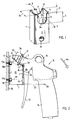
- the holder body 1 is made of a piece of pipe with a rectangular shape Cross section or floor plan made.
- the front is in the top Edge area or wall section 2 placed a first clearance 3, the an indentation with the depression with respect to the front, upper side edge 4 5 forms in the longitudinal direction or downwards.
- a second clearance 6 is on the opposite back of the bracket body 1 formed, namely also as an indentation of the rear, upper side edge 8 of the corresponding back wall section 7 with the in the longitudinal direction of the hollow Bracket body 1 extending recess 9. This is dimensioned shorter than the recess 5 of the first clearance 3.
- the clearance 3 leads to a Rear space 33 (see FIG. 2), the front of the front wall section, on the back of the rear wall section 7 and otherwise of the two remaining side walls between the wall sections 2, 7 is limited.
- the first cutout 3 is used to hang one in itself known compressed air gun 10 with a gun barrel 11, a compressed air outlet nozzle 12, an actuating pressure lever 13, a handle part 14 and a suspension eye 15, which is approximately in the longitudinal median plane with its ring shape of the gun barrel 11 and the hanging on a (not shown) Hook serves.
- the latter is achieved by the present invention with the holder body 1 and the exemption 3 replaced.
- the second, shorter exemption 6 is useful for extended air outlet nozzles, which then result in the second clearance 6 can extend into or through them.
- the additional arrangement of spacers see FIG. 9) between the Back 7 of the holder body 1 and a wall 16 expedient, what the holder body 1 is fixed by fastening screws 17a, 17b.
- fixing holes 18a, 18b formed, the back 7 of the Push bracket part 1 through.
- Facilitating the assembly of the top Fastening screw 17a in the upper fixing hole 18a serves the first Notch 3 in the front 2 of the bracket body 1.
- the assembly of the lower fastening screw 17b in the lower fixing hole 18b is used analogously a lower recess 19 which in the Front 2 in a common alignment 20 with the lower fixing hole 18b lies.
- the washer 21 need not be round, it can also have a square shape.
- the disk diameter 22 is dimensioned such that it exceeds the width 23 of the first clearance 3 and thus to the Clear edges of the front wall section 2 of the hollow Bracket body 1 can reach behind from the inside.
- the holder body 1 on a wall 16a of a machine tool be attached.
- an angle section part can also be used as an accessory to make assembly easier 29 may be provided.
- Whose leg 29a has fixing holes 30a, 30b, which in the holder body 1, the upper and lower fixing holes 18a, 18b can be assigned.
- the other leg has 29b also a fixing hole 30c, through which the angle profile part 29 on a (not shown) wall, such as that of a machine tool 4, can be attached.
- 6 can be assembled State between the lower end 31 of the bracket body 1 and the second, shorter, lower leg part 29b of the L-shaped angle profile part 29 Clearance 32 remain when mounting in an inaccessible environment can be useful.
- the L or U angle section part serving as a spacer 35 with its two parallel legs 35a, 35b is with its first leg 35a on a side wall of the Mounted body 1, which on the front wall section 2 with the exemption 3 immediately adjoins at a right angle. That’s it possible that an extremely long pistol barrel 36 parallel to the external Wall 16b can run and not abut there.
- the bracket body 37 is a U-shaped angle section with two designed free legs.
- the first, front leg forms the front Wall section 2 with the recess 3 open at the top, during the rear leg corresponds to the second wall section 7 and the Fixing holes 18a, 18b carries.
- Both wall sections 2, 7 go in one piece from a common bottom part 38 vertically and parallel opposite out. They delimit the rear space 33 between them for receiving a part the fluid gun.
- the bracket body 37 because of the extended gun barrel 36 also mounted on the external wall 16b via a spacer. This is in the example shown as an L-shaped angle 39 with a longer legs 39a and. mounted on the rear wall section 7 a shorter leg 39b mounted on the external wall 16b.
- the extended gun barrel 36 runs parallel and at a distance from the shorter L-leg 39b.
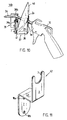
- the 10 is in the suspended gun 10 as a holding element transparent protective shield 40 used, which is attached to the gun barrel 36 and with its width or its diameter the entire rear space 33 of the bracket body 37 obliquely measured and towered over. Because of this results in interacting with gravity and the tipping edge 3a to which the gun barrel 36 can rock, one on the peripheral edge of the protective shield 40 lower stop 41, which abuts in the corner area, that in the rectangular Transition area from the bottom part 38 to the rear wall section 7.
- the lower stop 41 can additionally or alternatively to the attachment point or to the rear grip 2a in the rear Clearance area of the front wall section 2 may be present if the gun barrel 36 on the tipping edge 3a at the foot of the recess 3 of the front wall section 2 is present. In a modification of this, in Fig. 10 illustrated arrangement, it is also within the scope of the invention that the Gun barrel 36 does not rest on the tipping edge 3a.
- the Protective shield 40 with its lower stop 41 in the corresponding Corner area of the rear room 33 and in its the pistol barrel immediately surrounding inner circumference area with the stop or rear grip 2a on the Rear of the clearance area of the front wall section 3 rest, the gun barrel 6 being lifted off the tilting edge 3a (not drawn).
- the illustrated Executions of the arrangement according to the invention according to which Gun barrel 36 or gun 10 itself lie on the tipping edge 3a Advantage of mechanical relief of the fastening of the protective shield 40 or the washer 21.
- 11 is a further design of the Bracket body as an angle section part 42 with a front Wall section 2 as the first leg, which has the recess 3, and a rear or rear wall section 7 as the second Leg, which has the fixing holes 18a, 18b. These are for Assembly purposes easily accessible or not blocked because the two Wall sections 2, 7 of the common connecting part 43 each go one piece in opposite directions.
Landscapes
- Toys (AREA)
- Coating Apparatus (AREA)
- Details Or Accessories Of Spraying Plant Or Apparatus (AREA)
Abstract
Description
- Fig. 1
- eine perspektivische Längsansicht auf den erfindungsgemäßen Halterungskörper,
- Fig. 2
- das erfindungsgemäße Halterungssystem in Seitenansicht, wobei der Halterungskörper im Längsschnitt gemäß Linie II-II in Fig. 1 dargestellt ist,
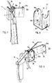
- Fig. 3
- die Anbringung des Halterungskörpers an einer Werkzeugmaschine in Vorderansicht,
- Fig. 4
- die Anbringung des Halterungskörpers mit einem Flachteil an einer weiteren Werkzeugmaschine mit eingehängter Druckluft-Pistole in perspektivischer Darstellung,
- Fig. 5
- in auseinandergezogener Darstellung die Anordnung des erfindungsgemäßen Halterungskörper mit einem Winkelprofilteil als Zubehör,
- Fig. 6
- die Anordnung gemäß Fig. 5 im zusammenmontierten Zustand in perspektivischer Darstellung,
- Fig. 7
- eine weitere, erfindungsgemäße Anordnung mit dem Halterungskörper gemäß Fig. 1,
- Fig. 8
- eine perspektivische Ansicht auf ein weiteres Ausführungsbeispiel für einen erfindungsgemäßen Halterungskörper,
- Fig. 9
- eine perspektivische Seitenansicht auf eine erfindungsgemäße Anordnung mit dem Halterungskörper nach Fig. 8
- Fig. 10
- eine alternative, erfindungsgemäße Anordnung mit dem Halterungskörper nach Fig. 8,
- Fig. 11
- ein weiteres Ausführungsbeispiel für einen erfindungsgemäßen Halterungskörper.
- 1 -
- Halterungskörper
- 2 -
- vorderer Wandungsabschnitt
- 2a -
- Hintergriff
- 3 -
- erste Freisparung
- 3a -
- Kippkante
- 4 -
- vordere, obere Seitenkante
- 5 -
- Vertiefung
- 6 -
- zweite Freisparung
- 7 -
- rückseitiger Wandungsabschnitt
- 8 -
- hintere, obere Seitenkante
- 9 -
- Vertiefung
- 10 -
- Druckluft-Pistole
- 11 -
- Pistolenlauf
- 12 -
- Austrittsdüse
- 13 -
- Druckhebel
- 14 -
- Griffteil
- 15 -
- Einhängeöse
- 16,16a,16b -
- Wandung
- 17a- 17b -
- Befestigungsschrauben
- 18a- 18b -
- Fixierbohrung
- 19 -
- Aussparung
- 20 -
- Flucht
- 21 -
- Ringscheibe
- 22 -
- Scheibendurchmesser
- 23 -
- Breite
- 24 -
- Anschlagfläche
- 25 -
- Gelenkansatz
- 26 -
- Schwerpunkt
- 27 -
- Hebelarm
- 28 -
- Flachteil
- 29 -
- Winkelprofilteil
- 29a -
- Schenkel
- 29b -
- Schenkel
- 30a, 30b, 30c -
- Fixierbohrung
- 31 -
- unteres Stirnende
- 32 -
- Abstand
- 33 -
- Hinterraum
- 34 -
- Abstand
- 35 -
- Winkelprofilteil
- 35a, b -
- Schenkel
- 36 -
- Pistolenlauf
- 37 -
- Halterungskörper
- 38 -
- Bodenteil
- 39 -
- L-Winkelprofilteil
- 40 -
- Schutzschild
- 41 -
- Anschlagstelle
- 42 -
- Winkelprofilteil
- 43 -
- Mittelteil
- 44 -
- Kippbewegung
Claims (23)
- Anordnung zur Halterung einer Fluid-, insbesondere Druckluft-Pistole (10) an einer von oben nach unten verlaufenden, externen Wandung (16,16a,16b) eines Gebäudes oder einer Maschine, mit einem daran befestigten, vorspringenden Halterungskörper (1, 37, 42), der zur Halterung der Pistole (10) eine Aufnahmeeinrichtung aufweist, und die Pistole (10) mit einem Halteelement (21, 40) versehen ist, das bei gehalterter Pistole (10) mit dem Halterungskörper in Eingriff steht, dadurch gekennzeichnet, daß die Aufnahmeeinrichtung folgendes umfaßt:einen in einer freien Oberkante endenden Wandungsabschnitt (2) des Halterungskörpers (1, 37, 42), der rückseitig einen freien Hinterraum (33) des Halterungskörpers (1, 37, 42) zur Aufnahme eines Teils der Pistole (10) abdeckt, undeine nach oben offene, von der Oberkante (4) ausgehend sich in dem Wandungsabschnitt (2) nach unten erstreckende Frei- oder Aussparung (3), welche zum Hinterraum (33) führt und die gehalterte Pistole (10) querschnittlich umgibt und/oder erfaßt,wobei die gehalterte Pistole (10) durch die Schwerkraft mit ihrem Halteelement (21,40) im Hinterraum (33) in Anschlag (2a) an eine Innenseite des Wandungsabschnitts (2) gebracht ist.
- Anordnung nach Anspruch 1, dadurch gekennzeichnet, daß die Pistole (10) mit ihrem Lauf (11), ihrer Austrittsdüse (12) und/oder ihrem Halteelement (21,40) den Hinterraum (33) des Halterungskörpers (1) über dessen Frei- oder Aussparung (3) durchsetzt.
- Anordnung nach Anspruch 1 oder 2, dadurch gekennzeichnet, daß die Pistole (10) auf einer Kante (3a) der Frei- oder Aussparung (3) aufliegt, wobei die Kante (3a) eine Gelenk- oder Drehstelle bildet, um welche die Pistole kippbar (44) ist.
- Anordnung nach Anspruch 3, dadurch gekennzeichnet, daß die Pistole (10) auf ihrem Außenmantel eine Anschlagfläche (24) aufweist, mit welcher sie durch die Schwerkraft um die Kante (3a) in Anlage auf die Außenseite, oder Außenmantelfläche des Wandungsabschnitt (2) des Halterungskörpers (1) unterhalb der Frei- oder Aussparung (3) gekippt (44) ist.
- Anordnung nach Anspruch 3, dadurch gekennzeichnet, daß die Pistole (10) auf ihrem Halteelement (21,40) eine zur erstgenannten Anschlagstelle (2a) zusätzliche oder alternative Anschlagstelle (41) aufweist, mit welcher sie durch die Schwerkraft um die Kante (3a) an eine Innenseite eines zweiten Wandungsabschnitts (7) gekippt ist, welcher dem erstgenannten Wandungsabschnitt (2) gegenüberliegt und den Hinterraum (33) mit abdeckt.
- Anordnung nach Anspruch 1 oder 2, gekennzeichnet durch ein derart weit bemessenes Halteelement (40), daß die Pistole (10) einzig über sein Halteelement (40) vom Halterungskörper (21,37) in dessen Hinterraum (33) getragen wird.
- Anordnung nach Anspruch 6, dadurch gekennzeichnet, daß das Halteelement (40) den gesamten Hinterraum (33) schräg durchmißt und an den Innenseiten gegenüberliegender Wandungsabschnitte (2,7) des Halterungskörpers (37) achsparallel versetzt anliegt.
- Anordnung nach einem der vorangehenden Ansprüche, dadurch gekennzeichnet, daß die Gestalt des Halteelements (21,40) zum Hintergreifen des erstgenannten Wandungsabschnitts (2) bei von der Frei- oder Aussparung (3) umgebener Pistole (10) ausgebildet ist.
- Anordnung nach Anspruch 8, dadurch gekennzeichnet, daß das Halteelement (21,40) als auf die Pistole aufgesteckte Ringscheibe (21) gestaltet ist, deren Weite, Durchmesser und/oder Radius größer als zumindest ein Teil der Frei- oder Aussparung (3).
- Anordnung nach einem der vorangehenden Ansprüche, gekennzeichnet durch wenigstens einen, zwischen der externen Wandung (16,16a,16b) und dem Halterungskörper (1,37,42) angeordneten Abstandshalter, der als Flach- oder Ein- oder Mehrfach-Winkelprofilteil (28,29,35) mit zwei frei abstehenden Schenkeln (29a,29b;35a,35b) ausgebildet ist, wobei der eine Schenkel (29b;35b) über ein oder mehrere Verbindungselemente (30c) mit der externen Wandung (16,16a,16b) oder sonstigen Fläche, und der andere Schenkel (29a;35a) über weitere Verbindungselemente (30a,30b) mit dem Halterungskörper (1,37,42) verbunden ist.
- Halterungskörper (1,37,42) für die Anordnung nach einem der vorangehenden Ansprüche, mit einem oder mehreren ersten Wandungsabschnitten (2), die zur Aufnahme einer Fluid-Pistole (10) ausgebildet sind, und mit wenigstens einen im Abstand (34) vom ersten Wandungsabschnitt (2) angeordneten, zweiten Wandungsabschnitt (7), der einer externen Wandung (16,16a,16b) oder sonstigen Fläche zugeordnete Befestigungselemente (18a,18b) aufweist, dadurch gekennzeichnet, daß wenigstens einer der ersten Wandungsabschnitte (2) mit einer darin endenden, nach oben offenen Frei- oder Aussparung (3) zum Umgeben der Fluid-Pistole (10) ausgebildet ist, und die Frei- oder Ausparung (3) zu einem vom ersten Wandungsabschnitt (2) rückseitig abdeckten Hinterraum (33) für die teilweise Aufnahme der Fluid-Pistole (10) führt.
- Halterungskörper nach Anspruch 11, gekennzeichnet durch die Form eines Hohlkörpers, zu deren Hohlraum (33) eine oder mehrere Frei- oder Aussparungen (3,6,9) in dem oder den ersten und/oder zweiten Wandungsabschnitten führen, wobei wenigstens eine Frei- oder Aussparung (3) in ihrem Ausmaß oder Umfang und ihrer Gestalt an den Querschnitt einer aufzunehmenden Fluid-Pistole (10) angepaßt ist, und die Befestigungselemente (18a,18b) des oder der zweiten Wandungsabschnitte im Abstand (34) von der Frei- oder Aussparung (3) des ersten Wandungsabschnitts angeordnet sind.
- Halterungskörper nach Anspruch 12, gekennzeichnet durch eine quaderartige Grundform, wobei die eine oder mehreren Frei- oder Aussparungen (3,19) einerseits und die Befestigungselemente (18a,18b) andererseits auf unterschiedlichen, vorzugsweise gegenüberliegenden Außenseiten (2,7) angeordnet sind.
- Halterungskörper nach Anspruch 13, dadurch gekennzeichnet, daß die Befestigungselemente (18a,18b) als Bohrungen ausgebildet sind, von denen eine oder mehrere mit der oder den Frei- oder Aussparungen (3,19) oder Montagebohrungen im ersten Wandungsabschnitt fluchten (20).
- Halterungskörper nach einem der vorangehenden Ansprüche, dadurch gekennzeichnet, daß auf zwei oder mehr einander gegenüberliegenden und/oder nebeneinanderliegenden Seiten (2,7) oder Mantelflächenabschnitten wenigstens je eine Frei- oder Aussparung (3;6) angeordnet ist.
- Halterungskörper nach einem der vorangehenden Ansprüche, gekennzeichnet durch eine Ausbildung als Rohrstück mit mehrkantigem Querschnitt.
- Halterungskörper nach Anspruch 11, dadurch gekennzeichnet, daß der erste und der zweite Wandungsabschnitt (2,7) die freien Schenkel eines Winkelprofilteils (37,42) bilden.
- Halterungskörper (37) nach Anspruch 17, dadurch gekennzeichnet, daß der erste und zweite Wandungsabschnitt (2,7) durch einen Bodenteil (38) miteinander verbunden sind und von diesem einander gegenüberliegend vorspringen.
- Halterungskörper nach Anspruch 18, dadurch gekennzeichnet, daß die Befestigungselemente (18a,18b) als Bohrungen in dem zweiten Wandungsabschnitt (7) ausgebildet sind, von denen eine oder mehrere mit der Frei- oder Aussparung (3,19) oder einer oder mehreren Montagebohrungen im ersten Wandungsabschnitt fluchten (20).
- Halterungskörper nach einem der vorangehenden Ansprüche, dadurch gekennzeichnet, daß der zweite Wandungsabschnitt (7) zusammen mit dem ersten Wandungsabschnitt (2) den Hinterraum (33) zur Aufnahme des Teils der Pistole (10) begrenzt.
- Halterungskörper (42) nach Anspruch 17, dadurch gekennzeichnet, daß der erste und zweite Wandungsabschnitt (2,7) durch einen Mittelteil (43) miteinander verbunden sind und von diesem in einander entgegengesetzte Richtungen vorspringen.
- Fluid-, insbesondere Druckluft-Pistole (10), ausgebildet zur Halterung in einer Anordnung nach einem der vorangehenden Ansprüche, gekennzeichnet durch ein Halteelement (21), das im Bereich des Pistolenlaufs (11) und/oder der Fluidaustrittsdüse (12) in Form einer flachebenen Ringscheibe (21) quer zu deren Längsrichtung vorspringend angeordnet ist.
- Pistole nach Anspruch 22, mit einer in den Pistolenlauf (11) einschraubbaren Fluidaustrittsdüse (12), dadurch gekennzeichnet, daß das Halteelement (21) in Form einer Ringscheibe auf einem Außengewinde der Schraubverbindung zwischen dem Pistolenlauf (11) und der Fluidaustrittsdüse (12) aufgesteckt und zwischen diesen geklemmt gehalten ist.
Applications Claiming Priority (2)
| Application Number | Priority Date | Filing Date | Title |
|---|---|---|---|
| DE19859842 | 1998-12-23 | ||
| DE19859842 | 1998-12-23 |
Publications (2)
| Publication Number | Publication Date |
|---|---|
| EP1013346A1 true EP1013346A1 (de) | 2000-06-28 |
| EP1013346B1 EP1013346B1 (de) | 2003-02-05 |
Family
ID=7892520
Family Applications (1)
| Application Number | Title | Priority Date | Filing Date |
|---|---|---|---|
| EP99122938A Expired - Lifetime EP1013346B1 (de) | 1998-12-23 | 1999-11-18 | Fluid-Pistolen-Halterungsanordnung sowie Halterungskörper dafür |
Country Status (3)
| Country | Link |
|---|---|
| EP (1) | EP1013346B1 (de) |
| AT (1) | ATE232143T1 (de) |
| DE (1) | DE59904217D1 (de) |
Cited By (1)
| Publication number | Priority date | Publication date | Assignee | Title |
|---|---|---|---|---|
| WO2005090038A3 (en) * | 2004-03-12 | 2006-02-16 | Intellipack | Dispenser system with dispenser holster |
Citations (6)
| Publication number | Priority date | Publication date | Assignee | Title |
|---|---|---|---|---|
| US1537237A (en) * | 1924-03-05 | 1925-05-12 | John D Kaestner | Nozzle holder |
| DE700489C (de) * | 1936-11-04 | 1940-12-20 | Junkers & Co | Aufhaengevorrichtung fuer Handbrausen |
| DE3337980C1 (de) * | 1983-10-19 | 1985-05-09 | Daimler-Benz Ag, 7000 Stuttgart | Einrichtung zum schnellen Wechseln von Spruehduesen zum Aufspruehen von Korrosionsschutzmittel in Karosseriehohlraeume |
| DE4000012A1 (de) * | 1990-01-02 | 1990-07-12 | Bernhard Clemens Kellermann | Halterung fuer spritzpistolen, insbesondere fuer air brush pistolen, mit regulierbarer duesenspitzenbefeuchtung |
| DE8506295U1 (de) * | 1985-03-05 | 1994-12-15 | Frohne, Norbert, 40211 Düsseldorf | Aufhängevorrichtung für Farb-Spritzpistolen in Fließbecher-Ausführung |
| EP0720870A2 (de) * | 1995-01-03 | 1996-07-10 | Ransburg Corporation | Halterung für eine Spritzpistole |
-
1999
- 1999-11-18 DE DE59904217T patent/DE59904217D1/de not_active Expired - Lifetime
- 1999-11-18 AT AT99122938T patent/ATE232143T1/de active
- 1999-11-18 EP EP99122938A patent/EP1013346B1/de not_active Expired - Lifetime
Patent Citations (6)
| Publication number | Priority date | Publication date | Assignee | Title |
|---|---|---|---|---|
| US1537237A (en) * | 1924-03-05 | 1925-05-12 | John D Kaestner | Nozzle holder |
| DE700489C (de) * | 1936-11-04 | 1940-12-20 | Junkers & Co | Aufhaengevorrichtung fuer Handbrausen |
| DE3337980C1 (de) * | 1983-10-19 | 1985-05-09 | Daimler-Benz Ag, 7000 Stuttgart | Einrichtung zum schnellen Wechseln von Spruehduesen zum Aufspruehen von Korrosionsschutzmittel in Karosseriehohlraeume |
| DE8506295U1 (de) * | 1985-03-05 | 1994-12-15 | Frohne, Norbert, 40211 Düsseldorf | Aufhängevorrichtung für Farb-Spritzpistolen in Fließbecher-Ausführung |
| DE4000012A1 (de) * | 1990-01-02 | 1990-07-12 | Bernhard Clemens Kellermann | Halterung fuer spritzpistolen, insbesondere fuer air brush pistolen, mit regulierbarer duesenspitzenbefeuchtung |
| EP0720870A2 (de) * | 1995-01-03 | 1996-07-10 | Ransburg Corporation | Halterung für eine Spritzpistole |
Cited By (1)
| Publication number | Priority date | Publication date | Assignee | Title |
|---|---|---|---|---|
| WO2005090038A3 (en) * | 2004-03-12 | 2006-02-16 | Intellipack | Dispenser system with dispenser holster |
Also Published As
| Publication number | Publication date |
|---|---|
| ATE232143T1 (de) | 2003-02-15 |
| EP1013346B1 (de) | 2003-02-05 |
| DE59904217D1 (de) | 2003-03-13 |
Similar Documents
| Publication | Publication Date | Title |
|---|---|---|
| DE60128109T2 (de) | Vorrichtung zum fixieren von teleskopisch zusammenwirkenden elementen | |
| DE4217304C2 (de) | Vorrichtung zur Höhenverstellung von Standfüßen | |
| DE4011778A1 (de) | Pneumatisches einschlagwerkzeug fuer befestigungselemente | |
| DE4100374C2 (de) | Lösbarer Verriegelungsmechanismus | |
| DE102009013475B4 (de) | Mittels einer Laufrolle verfahrbarer Gegenstand | |
| WO1997022444A1 (de) | Elektrohandwerkzeugmaschine | |
| DE3020838C2 (de) | ||
| DE19908259A1 (de) | Wischmopplatte mit Schwenkkarretiereinrichtung | |
| EP0377777B1 (de) | Knarre mit abwinkelbarem Griffstiel | |
| EP3286441B1 (de) | Teleskopstange, insbesondere für ein handführbares gerät | |
| EP3661866A1 (de) | Vorrichtung zur aufnahme und zum transport von lasten | |
| DE69800303T2 (de) | Kupplungselement zur Verbindung von zwei senkrecht zueinander angeordneten Stangen | |
| WO2020253958A1 (de) | Düsensystem für eine textilmaschine, schraubsystem für ein schnellbefestigungssystem und textilmaschine mit düsensystem | |
| EP1013346B1 (de) | Fluid-Pistolen-Halterungsanordnung sowie Halterungskörper dafür | |
| EP0437211A1 (de) | Halterung zur Anbringung eines Anbauteils an einem Trägerstab | |
| DE19902206C2 (de) | Aufhängevorrichtung für ein Werkzeug | |
| DE202009014717U1 (de) | Schnellwechsel-Spannzeug für Bohrwerkzeuge mit Spannfläche | |
| DE4326477A1 (de) | Vorrichtung zur lösbaren Verbindung einer Führungsstange | |
| EP0894579A1 (de) | Bohrmaschinenständer, insbesondere für Gesteinsbohrer, mit einem Wasserabsaugring | |
| EP0770442B1 (de) | Tieflochsäge | |
| DE29521059U1 (de) | Beschlag zum Montieren und Ausrichten einer Frontblende an einen Schubkasten o.dgl. | |
| DE202007007330U1 (de) | Handgriffvorrichtung für eine Hammerpistole | |
| DE3519544A1 (de) | Vorrichtung zur schnellen auswechselung insbes. von gartengeraeten an einer handhabe | |
| DE29819470U1 (de) | Aufnahmevorrichtung für Bohrstaub | |
| EP0502254B1 (de) | Umkehrbares Gerät zur Bodenbearbeitung zwischen Pflanzen |
Legal Events
| Date | Code | Title | Description |
|---|---|---|---|
| PUAI | Public reference made under article 153(3) epc to a published international application that has entered the european phase |
Free format text: ORIGINAL CODE: 0009012 |
|
| AK | Designated contracting states |
Kind code of ref document: A1 Designated state(s): AT DE |
|
| AX | Request for extension of the european patent |
Free format text: AL;LT;LV;MK;RO;SI |
|
| 17P | Request for examination filed |
Effective date: 20000714 |
|
| AKX | Designation fees paid |
Free format text: AT DE |
|
| 17Q | First examination report despatched |
Effective date: 20010606 |
|
| GRAG | Despatch of communication of intention to grant |
Free format text: ORIGINAL CODE: EPIDOS AGRA |
|
| RTI1 | Title (correction) |
Free format text: SUPPORT ARRANGEMENT FOR A FLUID GUN AND CORRESPONDING SUPPORTING DEVICE |
|
| GRAG | Despatch of communication of intention to grant |
Free format text: ORIGINAL CODE: EPIDOS AGRA |
|
| GRAH | Despatch of communication of intention to grant a patent |
Free format text: ORIGINAL CODE: EPIDOS IGRA |
|
| GRAH | Despatch of communication of intention to grant a patent |
Free format text: ORIGINAL CODE: EPIDOS IGRA |
|
| GRAA | (expected) grant |
Free format text: ORIGINAL CODE: 0009210 |
|
| AK | Designated contracting states |
Designated state(s): AT DE |
|
| REF | Corresponds to: |
Ref document number: 59904217 Country of ref document: DE Date of ref document: 20030313 Kind code of ref document: P |
|
| PLBE | No opposition filed within time limit |
Free format text: ORIGINAL CODE: 0009261 |
|
| STAA | Information on the status of an ep patent application or granted ep patent |
Free format text: STATUS: NO OPPOSITION FILED WITHIN TIME LIMIT |
|
| 26N | No opposition filed |
Effective date: 20031106 |
|
| PGFP | Annual fee paid to national office [announced via postgrant information from national office to epo] |
Ref country code: AT Payment date: 20131128 Year of fee payment: 15 |
|
| REG | Reference to a national code |
Ref country code: AT Ref legal event code: MM01 Ref document number: 232143 Country of ref document: AT Kind code of ref document: T Effective date: 20141118 |
|
| PG25 | Lapsed in a contracting state [announced via postgrant information from national office to epo] |
Ref country code: AT Free format text: LAPSE BECAUSE OF NON-PAYMENT OF DUE FEES Effective date: 20141118 |
|
| REG | Reference to a national code |
Ref country code: DE Ref legal event code: R079 Ref document number: 59904217 Country of ref document: DE Free format text: PREVIOUS MAIN CLASS: B05B0015060000 Ipc: B05B0015600000 |
|
| PGFP | Annual fee paid to national office [announced via postgrant information from national office to epo] |
Ref country code: DE Payment date: 20181130 Year of fee payment: 20 |
|
| REG | Reference to a national code |
Ref country code: DE Ref legal event code: R071 Ref document number: 59904217 Country of ref document: DE |