EP1013369A2 - Verfahren und Maschine zum Herstellen von Kronenrädern - Google Patents
Verfahren und Maschine zum Herstellen von Kronenrädern Download PDFInfo
- Publication number
- EP1013369A2 EP1013369A2 EP99310343A EP99310343A EP1013369A2 EP 1013369 A2 EP1013369 A2 EP 1013369A2 EP 99310343 A EP99310343 A EP 99310343A EP 99310343 A EP99310343 A EP 99310343A EP 1013369 A2 EP1013369 A2 EP 1013369A2
- Authority
- EP
- European Patent Office
- Prior art keywords
- gear
- grinding
- grinding wheel
- axis
- teeth
- Prior art date
- Legal status (The legal status is an assumption and is not a legal conclusion. Google has not performed a legal analysis and makes no representation as to the accuracy of the status listed.)
- Withdrawn
Links
Images





Classifications
-
- B—PERFORMING OPERATIONS; TRANSPORTING
- B23—MACHINE TOOLS; METAL-WORKING NOT OTHERWISE PROVIDED FOR
- B23F—MAKING GEARS OR TOOTHED RACKS
- B23F15/00—Methods or machines for making gear wheels of special kinds not covered by groups B23F7/00 - B23F13/00
- B23F15/06—Making gear teeth on the front surface of wheels, e.g. for clutches or couplings with toothed faces
-
- B—PERFORMING OPERATIONS; TRANSPORTING
- B23—MACHINE TOOLS; METAL-WORKING NOT OTHERWISE PROVIDED FOR
- B23F—MAKING GEARS OR TOOTHED RACKS
- B23F23/00—Accessories or equipment combined with or arranged in, or specially designed to form part of, gear-cutting machines
- B23F23/12—Other devices, e.g. tool holders; Checking devices for controlling workpieces in machines for manufacturing gear teeth
- B23F23/1225—Arrangements of abrasive wheel dressing devices on gear-cutting machines
-
- B—PERFORMING OPERATIONS; TRANSPORTING
- B23—MACHINE TOOLS; METAL-WORKING NOT OTHERWISE PROVIDED FOR
- B23F—MAKING GEARS OR TOOTHED RACKS
- B23F5/00—Making straight gear teeth involving moving a tool relatively to a workpiece with a rolling-off or an enveloping motion with respect to the gear teeth to be made
- B23F5/02—Making straight gear teeth involving moving a tool relatively to a workpiece with a rolling-off or an enveloping motion with respect to the gear teeth to be made by grinding
-
- B—PERFORMING OPERATIONS; TRANSPORTING
- B23—MACHINE TOOLS; METAL-WORKING NOT OTHERWISE PROVIDED FOR
- B23P—METAL-WORKING NOT OTHERWISE PROVIDED FOR; COMBINED OPERATIONS; UNIVERSAL MACHINE TOOLS
- B23P15/00—Making specific metal objects by operations not covered by a single other subclass or a group in this subclass
- B23P15/14—Making specific metal objects by operations not covered by a single other subclass or a group in this subclass gear parts, e.g. gear wheels
-
- Y—GENERAL TAGGING OF NEW TECHNOLOGICAL DEVELOPMENTS; GENERAL TAGGING OF CROSS-SECTIONAL TECHNOLOGIES SPANNING OVER SEVERAL SECTIONS OF THE IPC; TECHNICAL SUBJECTS COVERED BY FORMER USPC CROSS-REFERENCE ART COLLECTIONS [XRACs] AND DIGESTS
- Y10—TECHNICAL SUBJECTS COVERED BY FORMER USPC
- Y10T—TECHNICAL SUBJECTS COVERED BY FORMER US CLASSIFICATION
- Y10T409/00—Gear cutting, milling, or planing
- Y10T409/10—Gear cutting
- Y10T409/101431—Gear tooth shape generating
- Y10T409/103816—Milling with radial faced tool
- Y10T409/104134—Adapted to cut bevel gear
-
- Y—GENERAL TAGGING OF NEW TECHNOLOGICAL DEVELOPMENTS; GENERAL TAGGING OF CROSS-SECTIONAL TECHNOLOGIES SPANNING OVER SEVERAL SECTIONS OF THE IPC; TECHNICAL SUBJECTS COVERED BY FORMER USPC CROSS-REFERENCE ART COLLECTIONS [XRACs] AND DIGESTS
- Y10—TECHNICAL SUBJECTS COVERED BY FORMER USPC
- Y10T—TECHNICAL SUBJECTS COVERED BY FORMER US CLASSIFICATION
- Y10T409/00—Gear cutting, milling, or planing
- Y10T409/10—Gear cutting
- Y10T409/101431—Gear tooth shape generating
- Y10T409/103816—Milling with radial faced tool
- Y10T409/104134—Adapted to cut bevel gear
- Y10T409/104293—Adapted to cut bevel gear with means to continuously rotate work and means to co-form all teeth of gear
Definitions
- Face Gears for high power transmission is a relatively recent phenomenon. Historically, the transmission of power through a Face Gear set was limited to relatively low levels because of two factors: the tooth profile of the mating gears was generated by shaper cutting and, although as very acceptable tooth profile could be generated, the tooth produced by the shaping operation did not have a hardened surface. The tooth profile produced by the shaping operation required that the resulting Face Gear set be kept in almost perfect alignment.
- the Face Gear method of manufacture developed by the Fellows Corporation of shaping the gear teeth is a metal cutting process, which can only be applied to materials with suitable hardness and metal cutting characteristics. If the material is too hard, the shaper tool will not cut effectively.
- This shaping process can only be used effectively for finish cutting Face Gear teeth from metals suitable for low power applications. This process does not give the accuracy and surface finish required for higher power applications.
- Gear blanks are roughly machined as in the prior art, to produce toothed wheels wherein the gears produced have slightly enlarged teeth which makes allowance for a subsequent grinding operation.
- the Fellows shaper method is quite acceptable for the production of gears from blanks in this operation.
- the gear (now having enlarged shaped teeth) is thence subjected to a heat treatment operation to increase the surface hardness of the gear teeth.
- the rough cut gear will usually undergo some physical distortion which occurs during the heat treatment operation.
- the excessive material deliberately left on the gear teeth in the gear shaping operation will be sufficient to allow a subsequently distorted gear to be restored to its required shape by a grinding operation.
- the heat treated gear is now ground to the final shape and accuracy having the desired tooth profile.
- the resulting gear has a hardened tooth on a gear platform which is quite stable because of the stress relieving operation. Grinding is the only known method that will produce the accuracy and surface finish required for high power transmissibility applications.
- the surface grinding operation is a continuous operation with the grinding wheel and the face gear constantly rotating and moving such that the grinding wheel moves across the face of the rotating face gear in a controlled fashion.
- the grinding wheel has a surface which is commonly referred to as a "wonn" and in grinding a face gear, the surface of the grinding wheel is being constantly eroded by its constant engagement with the hardened metal surface of the previously formed teeth on the face gear. After deposits of the grinding debris, both from the erosion of the grinding wheel and from the material removed from the gear teeth during the grinding operation tend to be redeposited on the surface of the grinding wheel during the grinding operation.
- a suitable dressing wheel mounted on the grinding machine periodically restores the worm profile to its proper configuration.
- the tool In addition to having the dresser tool move in the X, Y and A axes, the tool must be capable of manual adjustment in two additional axes.
- Gear tooth grinding of spur gears is performed by the coordinated rotation of the grinding wheel and a gear blank so that the grinding wheel worm engages the gear blank in a constant meshing operation during the grinding operation.
- the area of engagements of the worm of the grinding wheel with the rotating spur gear is changed by moving the spur gear rectilinearly in its axial direction during a grinding operation to complete the tooth forming operation.
- the axis rotation of the grinding wheel relative to the face gear is significantly different.
- the grinding wheel must move the complete distance along the length of the teeth of the face gear and be parallel to the plane of the surface of the gear face in which the face gear teeth are being formed.
- the angle of the teeth generated in the gear face may vary widely with respect to the rotational axis of the face gear, thus grinding of the teeth of a face gear presents a substantial challenge.
- FIGURE 1 is an elevational view of a prior art spur gear cutting machine.
- FIGURE 2 is a partial view of a prior art blank guiding wheel (before the wheel is shaped).
- FIGURE 3 is a partial view of a spur gear grinding wheel of the prior art showing the dressing tool used to provide a cutting profile.
- FIGURE 4 is a perspective illustration of a face gear and a mating pinion gear.
- FIGURE 5 is a sectional view of a mating pinion and face gear.
- FIGURE 6 shows a sectional view of a face gear shaping apparatus of the prior art.
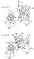
- FIGURE 7 shows an elevational view of the grinding apparatus of this invention for grinding teeth on a convex face gear.
- FIGURE 8 shows an elevational view of the grinding apparatus of FIGURE 7 adapted for grinding teeth on a concave face gear.
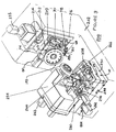
- FIGURE 9 is a perspective view of a complete grinding machine for grinding teeth on a convex face gear.
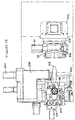
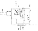
- FIGURE 10 is a plan view of the grinding wheel of this invention showing associated dresser apparatus motion.
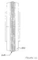
- FIGURE 11 is an elevational view of a grinding wheel showing a typical face gear grinding configuration used in this invention.
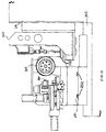
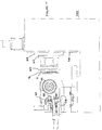
- FIGURE 12 is a plan view of the grinding machine of FIGURE 9 with the face gear removed.
- FIGURE 13 is an end view of the machine of FIGURE 9.
- FIGURE 14 is a front elevation of a concave face gear grinding apparatus.
- FIGURE 15 shows a perspective view of a face gear grinding apparatus adapted for producing teeth on a pinion gear.
- FIGURE 16 is a plan view of an alternative embodiment of the machine shown in FIGURE 9.
- FIGURE 17 is an elevational view of the machine of FIGURE 16.
- FIGURE 18 is an end view of the machine of FIGURE 16.
- FIGURE 1 shows a prior art spur gear grinding apparatus 10.
- a machine 12 (partially shown) is provided with a movable carrier 14 which is capable of executing rectilinear motion as shown by double arrow 16.
- Carrier 14 is provided with a gear driving head 18 which is connected to lead shaft 20.
- Shaft 20 is centered at its remote end in tailstock 22 to stabilize the shaft 20.
- a spur gear 24 is mounted on shaft 16 so as to be controllably rotated by driving head 18.
- a spur gear grinding wheel 26 is shown engaging the peripheral surface of spur gear 24. Grinding wheel 26 takes the form of the grinding wheel as shown in FIGURE 3 and must be capable of movement toward and away from gear 24 as indicated by double arrow 28. The rotation of the grinding wheel is coordinated with the rotation of the spur gear.
- the grinding wheel 26 is advanced toward the gear 24 while the gear 24 is synchronously rotated to be in step with the "worm" profile at grinding wheel 26, until the grinding wheel 26 has advanced to the desired depth into a selected area of the spur gear.
- the spur gear is now gradually moved in an axial direction to permit the grinding wheel to complete the grinding along the tooth length of the gear. This process is repeated for increased material removal until tooth size and profile are achieved.
- FIGURE 2 shows a grinding wheel 30 of the prior art before being dressed to have a grinding profile.
- FIGURE 3 shows a grinding wheel 36 which contains a peripheral worm profile 38 (used for grinding spur gear teeth as previously described), which profile is formed by dressing tool 40 which carries a special shaped dressing disc 42 to provide the worm profile.
- the dressing tool 40 is moved across the surface of the grinding wheel 36 as the grinding wheel 36 rotates.
- the disc 42 is advanced into the surface of the wheel 36 until the desired tooth form is achieved.
- the shape of the profile on the surface of wheel 38 is formed by the shape of the profile of grinding disc 42 (i.e. the axis of rotation of disc 42 is usually parallel to the axis of rotation of wheel 36).
- FIGURE 4 shows an illustration of a face gear 50 and a meshing pinion 52.
- the tccth 54 on face gear 50 extend in a radial direction; the teeth 56 on pinion 52 are parallel to the axis rotation of the pinion 52.
- FIGURE 5 shows the face gear 50 and pinion in section.
- the teeth 54 and 56 are shown in a meshed condition.
- FIGURE 6 is an illustration of a prior art method of shaping the teeth on face gear 50 by shaper cutter 60.
- the shaper cutter 60 is reciprocated in an axial direction (as shown by arrows 62) while it and the face gear 50 are simultaneously rotated so that the face gear 50 and the shaper cutter 60 are constantly moving in a simulated meshing engagement, until the desired tooth form has been generated.
- FIGURE 7 is an illustration of a face gear work head 68 and face gear grinding head 100 used for grinding the teeth of convex shaped face gear 70.
- convex face gear 70 is mounted on a controllable rotating table 72 so as to rotate about axis 74.
- Rotating table 72 is pivotably mounted on base 76. The pivoting action occurs about pivot 78.
- Motor 80 serves to drive the rotating table 72 through a suitable drive.
- the degree of pivot of the rotating table 72 is closely controlled by pivot selector 82.
- the gear face angle is maintained in a vertical orientation at the point of grinding.
- the whole rotating face gear head 68 must be capable of executing controlled motion in a vertical direction during a tooth grinding operation as shown by arrow 90.
- Grinding head 100 has a grinding wheel 102 rotatably mounted thereon.
- the grinding head 100 is precisely located with respect to face gear work head 68 and the grinding wheel 102.
- CNC control permits controlled motion in the vertical and horizontal axis.
- Grinding wheel 102 is provided with a special worm profile (see FIGURES 10 and 11) and the grinding operation is carried out by advancing grinding wheel 102 toward face gear 70 so that the grinding wheel profile and the face gear teeth mesh precisely i.e. the worm of the grinding wheel 102 has a profile which meshes with the teeth of the face gear 70.
- the feed mechanism for generating the teeth on the face gear 70 slowly moves the face gear 70 in a vertical direction until the grinding wheel has traversed the entire width of the tooth face 71 of face gear 70.
- the grinding wheel 102 is gradually advanced into the surface 71 of face gear 70 with each succeeding pass until the desired tooth profile is produced.
- FIGURE 8 shows the same machine adapted to grind teeth on a concave face gear 106.
- FIGURE 8 shows face gear work head 68 having the face gear rotating table 72 pivoted through an angle of about 25° from the position shown in FIGURE 7.
- the teeth of the concave face gear 106 are in a vertical plane at the point of engagement with grinding wheel 102.
- the grinding of the teeth is accomplished in the same manner as the tooth generating operation carried out in FIGURE 7.
- FIGURE 9 shows the full gear grinding machine 200 in perspective.
- a base 202 is provided to permit the face gear work head 68 to be mounted thereon in a predetermined fashion.
- This apparatus drives a rotating table 72 on which face gear 70 is mounted in a controlled manner about its axis (designated axis B).
- the pivot 78 is used to set the face gear at a predetermined angle (face angle) in machine 200 manually and is locked in this position.
- This pivot mechanism 210 is mounted on a swivel 212 on work table 214 to permit the face gear to have a manually adjustable angular setting.
- the work table 214 is constrained to permit it to move in a vertical plane along rails 216 by drive motor 222. This vertical axis is designated as the "W" axis.
- Drive motor 80 drives face gear 70 through transmission 209 and this, in turn, is mounted via pivot mechanism 78 and pivot supports 220 to the work table swivel 212 which allows the pivot mechanism to also swivel about its mounting on the work table 214.
- the swivel axis is designated as file WTS axis.
- the grinding head 100 (on which grinding wheel 102 is mounted) is mounted on base 202 in such a manner that grinding wheel 102 may be moved toward and away from face gear work head 68 and grinding wheel 102 may move tangentially to face gear work head 68 as well.
- Grinding head 100 is permitted to move along rails 259 to produce motion of the carriage 254 toward and away from the face gear work head 68.
- The is a "feed" axis which is designated as the "V" axis.
- Carriage 254 is also mounted on rails 252 to produce motion of the grinding wheel 102 in a tangential direction with respect to face gear 70. This axis is designated as the "TF" axis.
- Grinding table 258 is capable of pivoting carriage 254 about pivot 260. This is the grinding wheel pivot axis and is designated as the "WT" axis.
- Grinding wheel 102 rotates about an axis designated as axis "C” and is driven by motor 262 which is integrally mounted on carriage 254. Grinding wheel 102 has a predetermined profile inscribed on its surface as shown in FIGURES 10 and 11.
- axes "TF" and “WT” are set with respect to the tooth configuration already existing on face gear 70 and locked.
- Fe gear 70 has already undergone tooth shaping and surface hardening operations before being mounted in machine 200.
- motor 262 is rotating the grinding wheel 102 about axis "C” and the carriage 254 is fed along the "V" axis toward face gear 70 until the desired grinding position is reached.
- the face gear table 214 undergoes controlled movement along the feed axis "W” until the grinding wheel has moved sufficiently so that the entire tooth face 71 of face gear 70 has been traversed by grinding wheel 102.
- the grinding wheel 102 is then moved slightly toward table 214 and the grinding operation is repeated until the desired depth of the tooth form and shape is generated.
- a rotary diamond dressing tool assembly 264 is also mounted on grinding table 258 on rails 256.
- the assembly 264 includes a rotary device 266 which rotates a diamond impregnated disc 280 (see FIGURE 10).
- the disc 280 is used to generate (by abrasion) a prescribed form 268 in grinding wheel 102 (see FIGURE 11).
- Device 266 is adjustable in height and angle on and about post 270 on which device 266 is mounted.
- the entire dresser assembly 264 is mounted on table 258 so as to be capable of controlled motion in three axes.
- a first axis of motion allows the dresser assembly mounted on feed table 274 to move backwards and forwards along rails 272 away from and towards grinding wheel 102. This axis is designated as the "Y" axis.
- Movement of the dresser tool along rails 256 in a translatory fashion is designated as the "X" axis. Movement of the dresser wheel 280 about post 270 in an angular fashion will define the angular axis "A”.
- the grinding wheel profile 268 demands that the movement of the feed table assembly 274 for the dresser assembly 264 be synchronized with the rotation of grinding wheel 102 in order that disc 280 of the dresser assembly 264 properly meshes with the profile 268 of grinding wheel 102.
- the grinding operation of the partially completed and surface hardened face gear 70 is as follows:
- the rotating table 72 is manually set to a predetermined tilt (WTT) and swivel (WTS) setting and these positions are locked.
- the partially finished gear is mounted on the face plate 72 so as to have a predetermined angular position on axis "B".
- the grinding wheel carriage 254 is set at the appropriate angle on the pivot axis WT and locked. Carriage 254 is moved along rails 252 until the grinding wheel 102 is set at a predetermined position on the "TF" axis with respect to face gear 70 and locked in this position.
- the rotating grinding wheel 102 is now moved along the "V" "feed” axis to move toward the partially finished rotating face gear 70 until a desired face gear grinding position is achieved.
- Work table 214 is now moved vertically along rails 216 to permit the grinding wheel 102 to traverse the entire face of the gear 70 as the grinding operation continues. This process is repeated in a series of grinding passes until the desired depth and tooth configuration is generated in face gear 70.
- the profile of the grinding wheel 102 must be restored. At this time, the grinding wheel 102 is retracted from the face gear 70 and the dresser assembly 264 is brought into position on rails 272 and 256 to engage grinding wheel 102 and to restore the profile 268 on wheel 102 to its original profile.
- the grinding disc 280 is engaged with grinding wheel 102 in accordance with CNC control to move in a controlled manner to restore the profile 268 to wheel 102 to its required dimensional shape.
- FIGURE 15 shows the apparatus of FIGURE 9 modified to permit the finish grinding of a pinion 300.
- Pinion 300 in this instance, is a tapered spur gear pinion.
- Grinding wheel 302 now carries a significantly different profile from the profile inscribed in the surface of grinding wheel 102 for face gear grinding.
- the profile inscribed on the surface of wheel 302 is similar to that shown in FIGURE 3.
- the face gear work head 68 of FIGURE 9 has been replaced with work table 304 which supports and rotates pinion 300 during grinding.
- Tapered pinion 300 rotates about an axis designated as "B1" in an angular motion synchronized with grinding wheel 302.
- the work table assembly 304 is capable of vertical translatory motion along rails 216 designated the "W" axis as previously in FIGURE 9.
- the motion of the grinding wheel 302 along the "V" axis is CNC controlled; the movement of the pinion 300 along the "W” axis is CNC controlled. It will be obvious to those skilled in the art that the motion of the grinding wheel in the "V" axis must be carefully coordinated with the motion of table 304 along rails 216 in order to produce the tapered spur gear pinion 300.
- Axis Definition Table is set out below: AXIS DEFINITION CONTROL C Grinding Wheel 102 (302) Rotation CNC V Grinding Wheel 102 (302) in Feed CNC WT Grinding Wheel 102 (302) Tilt Manual TF Grinding Wheel 102 (302) Tangential Feed Manual B Rotating Table 72 Rotation (Face Gears) CNC B1 Driving head 318 Rotation (Tapered CNC Spur Gear Pinion) W Work Tablc 214 Axial Feed CNC WTS Work Head 212 (68, 304) Swivel Manual WTT Work Table 78 Tilt Manual A Dresser Tool 264 Rotary Feed CNC X Dresser Tool 264 Cross Feed CNC Y Dresser Tool 264 In Feed CNC DH Dresser Tool 264 Height Manual DT Dresser Tool 264 Tilt Manual
- This machine 200 utilizes a CNC system that enables the axes under its control to be moved in a predetermined manner via a set of instructions in a program. Numerous programs will be created to control the dressing cycle and gear grinding cycle of the machine 200 for different configurations of gears.
- the CNC control enables the axes of motion to be continually synchronized even when switching between the dressing and grinding cycles.
- the work table 212 swivel "WTS" is usually set in the vertical position and locked.
- the work table 214 tilt "WTT" is set to the required Face Gear face angle and locked.
- the grinding wheel tangential feed "TF" is adjusted to center the wheel with respect to the central axis of the gear.
- Dresser rotary device 266 tilt is set for angular clearance "DT" and diamond disc 280/grinding wheel 102 (302) center line height "DH".
- CNC programs stored in the memory of the CNC control are selected to control this process. These programs command the motion of dresser axes X, Y, A, and grinding wheel 102 (302) axis C in a prescribed manner to generate the required form on the grinding wheel (FIGURE 11 work profile 268). These programs control the speed and direction of rotation of the grinding wheel 102 (302) with respect to the speed and direction of motion of the dresser assembly 264, axes X, Y and A.
- the speed of rotation of the grinding wheel 102 (302) (axis C) relative to the speed of rotation of the gear 70 (axis B) being ground is controlled.
- This relationship is controlled via an electronic gearbox, which is a feature of the CNC. It is an important feature as the grinding process simulates the meshing of a worm gear which is the Grinding Wheel 102 (302) with a face gear such as 70 which is the gear being finish ground. Also via the program and CNC, the following functions are also controlled:
- FIGURE 16 is a plan view of the modified apparatus 400 for producing the desired tooth configuration on face gear 70.
- Modified face gear apparatus comprises the same base 202 which is shown in FIGURE 9.
- Work table 414 (See FIGURE 17) is driven by a drive motor 222 to move up and down along rails 216 (along the "W" axis) in a vertical plane.
- Face gear 70 is mounted on face gear rotating table 407 which is driven by a CNC drive motor (similar to drive motor 218 of FIGURE 9) for rotation of face gear 70 about the "B" axis.
- Grinding wheel carriage 254 is confined to move in a translationary fashion along rails 256 along the "TF" axis.
- the grinding wheel carriage is also permitted to moved back and forth along rails 259 ("V" axis) as driven by drive motor 261. It is this motion which must be very closely controlled and coordinated with work table motion along rails 216 during a grinding operation because the face plane 71 of gear 70 is no longer in a vertical plane at the grinding contact area.
- FIGURES 16-18 are somewhat simplified but an increasing amount of software is required to control the motion of grinding wheel 102.
- composition of the basic material for gear 70 or pinion 300 which may be used successfully to accomplish this invention is:
Landscapes
- Engineering & Computer Science (AREA)
- Mechanical Engineering (AREA)
- Grinding-Machine Dressing And Accessory Apparatuses (AREA)
- Gear Processing (AREA)
Applications Claiming Priority (2)
| Application Number | Priority Date | Filing Date | Title |
|---|---|---|---|
| US11319398P | 1998-12-21 | 1998-12-21 | |
| US113193 | 1998-12-21 |
Publications (2)
| Publication Number | Publication Date |
|---|---|
| EP1013369A2 true EP1013369A2 (de) | 2000-06-28 |
| EP1013369A3 EP1013369A3 (de) | 2002-03-13 |
Family
ID=22348072
Family Applications (1)
| Application Number | Title | Priority Date | Filing Date |
|---|---|---|---|
| EP99310343A Withdrawn EP1013369A3 (de) | 1998-12-21 | 1999-12-21 | Verfahren und Maschine zum Herstellen von Kronenrädern |
Country Status (3)
| Country | Link |
|---|---|
| US (1) | US6390894B1 (de) |
| EP (1) | EP1013369A3 (de) |
| CA (1) | CA2292857C (de) |
Cited By (3)
| Publication number | Priority date | Publication date | Assignee | Title |
|---|---|---|---|---|
| CN102264510A (zh) * | 2008-12-22 | 2011-11-30 | 三菱重工业株式会社 | 内齿轮磨削机和用于桶状螺纹刀具的修整方法 |
| CN104551265A (zh) * | 2013-10-09 | 2015-04-29 | 唐进元 | 一种盘形刀具加工面齿轮的方法 |
| CN110280983A (zh) * | 2019-07-17 | 2019-09-27 | 河南科技大学 | 一种面齿轮车齿加工方法 |
Families Citing this family (40)
| Publication number | Priority date | Publication date | Assignee | Title |
|---|---|---|---|---|
| US6669415B2 (en) * | 2001-02-16 | 2003-12-30 | The Gleason Works | Machine for producing bevel gears |
| DE10209971A1 (de) * | 2002-03-07 | 2003-10-02 | Liebherr Verzahntech Gmbh | Wälzstoßmaschine und Verfahren zum Betrieb einer Wälzstoßmaschine |
| CA2581724C (en) * | 2005-02-03 | 2010-11-30 | David J. Fisher | Method and apparatus for manufacturing a face gear |
| US7527548B2 (en) * | 2005-03-10 | 2009-05-05 | Sikorsky Aircraft Corporation | System and method for precision machining of high hardness gear teeth and splines |
| US8062094B2 (en) * | 2005-06-29 | 2011-11-22 | Deere & Company | Process of durability improvement of gear tooth flank surface |
| CN100415427C (zh) * | 2005-07-29 | 2008-09-03 | 十堰义兴工业发展有限公司 | 端面齿零件的端面齿加工使用的回转夹具 |
| JP4895649B2 (ja) * | 2006-03-20 | 2012-03-14 | アイシン精機株式会社 | フェースギヤ歯面をもつ部材の製造方法 |
| US20090112355A1 (en) * | 2007-03-02 | 2009-04-30 | Mori Seiki Usa, Inc. | Device and Method for Dressing Cutting Tools |
| DE102007020479B4 (de) * | 2007-04-27 | 2010-10-21 | Kapp Gmbh | Verfahren und Schleifmaschine zum Profilieren eines Schleifwerkzeugs |
| JP4834656B2 (ja) * | 2007-12-30 | 2011-12-14 | 本田技研工業株式会社 | ポジションセンサの位置決め装置 |
| US7585206B2 (en) * | 2008-01-22 | 2009-09-08 | Royal Master Grinders, Inc. | Spool to spool continuous through feed system |
| JP5700854B2 (ja) | 2009-08-03 | 2015-04-15 | ザ グリーソン ワークス | フェースギヤを製造するための方法及び工具 |
| CN102548698B (zh) * | 2009-09-25 | 2014-09-10 | 格里森工场 | 用于齿轮的倒角和/或去毛刺的设备 |
| TWD138091S1 (zh) * | 2009-09-28 | 2010-12-01 | 三菱重工業股份有限公司 | 大型齒輪加工機 |
| RU2518818C2 (ru) | 2010-01-29 | 2014-06-10 | Те Глисон Воркс | Способ непрерывного изготовления плоских зубчатых колес |
| CN102151908A (zh) * | 2011-01-05 | 2011-08-17 | 苏州天魁电子科技有限公司 | 游星轮插齿装置 |
| US8784155B2 (en) * | 2011-05-16 | 2014-07-22 | Huaizhong Guo | Multi-carriage symmetrical numerically controlled coordinate grinding machine |
| CN102248228B (zh) * | 2011-07-18 | 2013-02-13 | 北京航空航天大学 | 一种面齿轮数控滚齿加工装置 |
| CN102423818A (zh) * | 2011-10-10 | 2012-04-25 | 唐进元 | 一种利用成形砂轮磨削面齿轮的方法 |
| CN102407389A (zh) * | 2011-10-10 | 2012-04-11 | 唐进元 | 一种面齿轮数控磨齿机床 |
| CN102423820A (zh) * | 2011-10-10 | 2012-04-25 | 唐进元 | 基于蜗杆砂轮的面齿轮磨齿加工方法 |
| CN102423819A (zh) * | 2011-10-17 | 2012-04-25 | 唐进元 | 一种面齿轮数控磨削加工机床 |
| US8844106B2 (en) * | 2011-11-10 | 2014-09-30 | Lam Research Corporation | Installation fixture for elastomer bands and methods of using the same |
| CN103128385B (zh) * | 2011-11-24 | 2015-09-09 | 深圳市兆威机电有限公司 | 一种注塑面齿轮电极及注塑面齿轮的加工方法 |
| CN102601459A (zh) * | 2012-03-20 | 2012-07-25 | 唐进元 | 基于圆柱齿轮成形砂轮磨齿机床的面齿轮磨削加工方法 |
| CN102581386A (zh) * | 2012-03-20 | 2012-07-18 | 唐进元 | 基于圆柱齿轮蜗杆磨齿机床的面齿轮磨齿加工方法 |
| JP6016584B2 (ja) * | 2012-11-08 | 2016-10-26 | 東京エレクトロン株式会社 | ロードロック装置 |
| US10016933B2 (en) * | 2013-04-23 | 2018-07-10 | Apple Inc. | Rotational assembly method and apparatus |
| US9583377B2 (en) | 2013-12-17 | 2017-02-28 | Lam Research Corporation | Installation fixture for elastomer bands |
| TWD186171S (zh) * | 2016-09-09 | 2017-10-21 | 葛里森工具公司 | 計量機 |
| TWD189090S (zh) * | 2016-09-09 | 2018-03-11 | 葛里森工具公司 | 金屬加工切割或研磨機 |
| TWD187428S (zh) * | 2016-09-09 | 2017-12-21 | 葛里森工具公司 | 金屬加工切割或研磨機 |
| DE102017000260A1 (de) * | 2017-01-12 | 2018-07-12 | Gleason-Pfauter Maschinenfabrik Gmbh | Verfahren zur hartfeinbearbeitung von verzahnungen, insbesondere innenverzahnungen und dazu geeignete werkzeugmaschine |
| EP3348354B1 (de) * | 2017-01-16 | 2020-01-08 | Klingelnberg AG | Verfahren zum bearbeiten von kegelrädern unter einsatz einer exzentrisch bewegten, abrichtbaren topfschleifscheibe |
| CN109202543A (zh) * | 2017-12-03 | 2019-01-15 | 中国航空工业集团公司北京航空精密机械研究所 | 一种高精度直刃刀具后刀面加工及修磨方法 |
| CN108465883B (zh) * | 2018-03-21 | 2019-10-29 | 西安科技大学 | 直刃刀具制造各类面齿轮的加工设备及加工方法 |
| CN113618521A (zh) * | 2020-05-07 | 2021-11-09 | 广东博智林机器人有限公司 | 切削打磨头、打磨执行端及打磨设备 |
| CN113927483B (zh) * | 2020-07-14 | 2022-12-09 | 中南大学 | 一种面齿轮蜗杆砂轮修整方法 |
| CN113400197B (zh) * | 2021-06-23 | 2022-07-26 | 重庆大学 | 一种面齿轮磨削用鼓形蜗杆砂轮成形修整方法 |
| CN115592370A (zh) * | 2021-07-09 | 2023-01-13 | 三赢科技(深圳)有限公司(Cn) | 拆卸装置 |
Family Cites Families (12)
| Publication number | Priority date | Publication date | Assignee | Title |
|---|---|---|---|---|
| US3213756A (en) * | 1963-09-26 | 1965-10-26 | Gleason Works | Gear machine and indexing mechanism therefor |
| US4981402A (en) * | 1987-08-24 | 1991-01-01 | The Gleason Works | Multi-axis bevel and hypoid gear generating machine |
| NL8800472A (nl) * | 1988-02-24 | 1989-09-18 | Hankamp Bv | Werkwijze voor het vervaardigen en/of nabewerken van kroonwielen. |
| EP0355318A1 (de) * | 1988-08-16 | 1990-02-28 | Werkzeugmaschinenfabrik Oerlikon-Bührle AG | Vorrichtung zum Einstellen von Trommeln einer Kegelradverzahnungsmaschine |
| US5174699A (en) * | 1989-05-17 | 1992-12-29 | Hermann Pfauter Gmbh & Co. | Method for finishing gears via skiving |
| US5116173A (en) * | 1991-02-26 | 1992-05-26 | The Gleason Works | Method of generating bevel and hypoid gears |
| US5175962A (en) * | 1991-09-05 | 1993-01-05 | The Gleason Works | Method of and apparatus for machining spur and helical gears |
| EP0883460B1 (de) * | 1996-02-29 | 2002-05-15 | The Gleason Works | Verfahren zum bearbeiten von zahnrädern während des teilens |
| US5823857A (en) | 1996-04-23 | 1998-10-20 | Mcdonnell Douglas Helicopter Company | Apparatus and method for precision grinding of face gears |
| US6146253A (en) * | 1996-04-23 | 2000-11-14 | Mcdonnell Douglas Helicopter Company | Apparatus and method for precision grinding face gear |
| DE19625370C1 (de) * | 1996-06-25 | 1997-04-30 | Reishauer Ag | Schleifmaschine zum Schleifen von Stirnzahnrädern |
| US6120355A (en) * | 1998-09-03 | 2000-09-19 | The Gleason Works | Method and apparatus for lapping gears |
-
1999
- 1999-12-20 US US09/466,649 patent/US6390894B1/en not_active Expired - Lifetime
- 1999-12-21 CA CA2292857A patent/CA2292857C/en not_active Expired - Fee Related
- 1999-12-21 EP EP99310343A patent/EP1013369A3/de not_active Withdrawn
Cited By (5)
| Publication number | Priority date | Publication date | Assignee | Title |
|---|---|---|---|---|
| CN102264510A (zh) * | 2008-12-22 | 2011-11-30 | 三菱重工业株式会社 | 内齿轮磨削机和用于桶状螺纹刀具的修整方法 |
| CN102264510B (zh) * | 2008-12-22 | 2013-10-02 | 三菱重工业株式会社 | 内齿轮磨削机和用于桶状螺纹刀具的修整方法 |
| CN104551265A (zh) * | 2013-10-09 | 2015-04-29 | 唐进元 | 一种盘形刀具加工面齿轮的方法 |
| CN110280983A (zh) * | 2019-07-17 | 2019-09-27 | 河南科技大学 | 一种面齿轮车齿加工方法 |
| CN110280983B (zh) * | 2019-07-17 | 2021-04-23 | 河南科技大学 | 一种面齿轮车齿加工方法 |
Also Published As
| Publication number | Publication date |
|---|---|
| US6390894B1 (en) | 2002-05-21 |
| EP1013369A3 (de) | 2002-03-13 |
| CA2292857A1 (en) | 2000-06-12 |
| CA2292857C (en) | 2010-02-09 |
Similar Documents
| Publication | Publication Date | Title |
|---|---|---|
| US6390894B1 (en) | Face gear manufacturing method and apparatus | |
| CA2581724C (en) | Method and apparatus for manufacturing a face gear | |
| JP2899417B2 (ja) | ねじ切りされたといし車、目直しする方法および加工物のといし車による研削 | |
| EP0758571B2 (de) | Verfahren zur Erzeugung einer konkaven Oberfläche aus einem Brillenglasrohling | |
| JP2550038B2 (ja) | 曲がり歯を備えた傘歯車対の歯車の歯の研削方法及びこの方法を実施するための装置 | |
| US8460064B2 (en) | Method of dressing barrel worm-shaped tool, dressing apparatus, and internal-gear grinding machine | |
| DE102006061759B4 (de) | Verzahnungsschleifmaschine und Verfahren zum Schleifen eines Werkstücks | |
| US3916569A (en) | Methods of and means for producing helically toothed gears | |
| DE3320042C2 (de) | ||
| EP0330289B1 (de) | Verfahren zur Herstellung und/oder Fertigbearbeitung von Planrädern | |
| EP2529871A2 (de) | Verfahren zum Abrichten eines Werkzeugs | |
| US4012990A (en) | Device for trimming and bevelling gear teeth | |
| US6497610B1 (en) | Process for dressing an internal or external gear tool for fine machining of tooth profiles | |
| US5014467A (en) | Method and machine for the discontinuous generating grinding with indexing | |
| JP2582978B2 (ja) | 長手方向に湾曲した歯のギヤの歯を形成する方法 | |
| DE4207511A1 (de) | Verfahren zum schleifen von evolventenzaehnen mit hilfe einer innenschraubenden konvexen globoidschraubschnecke als nachformbares schleifwerkzeug | |
| US2270422A (en) | Method of cutting gears | |
| US20180200813A1 (en) | Method for fine processing a toothing, a fine processing machine for performing the method and a computer program for controlling the machine | |
| US3213567A (en) | Gear grinding machine and method of dressing the grinding wheel thereof | |
| US2828583A (en) | Tool sharpening machine and method | |
| JP3709473B2 (ja) | 歯車の研削方法および歯車の研削装置 | |
| JP3138053U (ja) | 歯車研削用砥石の研削面の整形装置 | |
| DE10131060A1 (de) | Vorrichtung zum Herstellen und Bearbeiten der Gerad- bzw. Schrägverzahnung von Werkstücken | |
| DD255296B3 (de) | Verzahnmaschine mit cnc-steuerung zur herstellung von kegelraedern | |
| JP2005081472A (ja) | 歯車研削用砥石の研削面の整形方法 |
Legal Events
| Date | Code | Title | Description |
|---|---|---|---|
| PUAI | Public reference made under article 153(3) epc to a published international application that has entered the european phase |
Free format text: ORIGINAL CODE: 0009012 |
|
| 17P | Request for examination filed |
Effective date: 20000121 |
|
| AK | Designated contracting states |
Kind code of ref document: A2 Designated state(s): AT BE CH CY DE DK ES FI FR GB GR IE IT LI LU MC NL PT SE |
|
| AX | Request for extension of the european patent |
Free format text: AL;LT;LV;MK;RO;SI |
|
| RIC1 | Information provided on ipc code assigned before grant |
Free format text: 7B 23F 15/06 A, 7B 23F 19/00 B, 7B 23F 1/02 B, 7B 23P 15/14 - |
|
| PUAL | Search report despatched |
Free format text: ORIGINAL CODE: 0009013 |
|
| AK | Designated contracting states |
Kind code of ref document: A3 Designated state(s): AT BE CH CY DE DK ES FI FR GB GR IE IT LI LU MC NL PT SE |
|
| AX | Request for extension of the european patent |
Free format text: AL;LT;LV;MK;RO;SI |
|
| STAA | Information on the status of an ep patent application or granted ep patent |
Free format text: STATUS: THE APPLICATION HAS BEEN WITHDRAWN |
|
| 18W | Application withdrawn |
Withdrawal date: 20020516 |