EP1013375A2 - Dispositif d'accouplement avec deux parties d'accouplement, et un dispositif de serrage - Google Patents
Dispositif d'accouplement avec deux parties d'accouplement, et un dispositif de serrage Download PDFInfo
- Publication number
- EP1013375A2 EP1013375A2 EP99124907A EP99124907A EP1013375A2 EP 1013375 A2 EP1013375 A2 EP 1013375A2 EP 99124907 A EP99124907 A EP 99124907A EP 99124907 A EP99124907 A EP 99124907A EP 1013375 A2 EP1013375 A2 EP 1013375A2
- Authority
- EP
- European Patent Office
- Prior art keywords
- coupling
- coupling member
- counter
- reference surfaces
- additional
- Prior art date
- Legal status (The legal status is an assumption and is not a legal conclusion. Google has not performed a legal analysis and makes no representation as to the accuracy of the status listed.)
- Granted
Links
- 230000008878 coupling Effects 0.000 title claims abstract description 86
- 238000010168 coupling process Methods 0.000 title claims abstract description 86
- 238000005859 coupling reaction Methods 0.000 title claims abstract description 86
- 210000000056 organ Anatomy 0.000 claims description 5
- 230000035515 penetration Effects 0.000 description 3
- 229910000639 Spring steel Inorganic materials 0.000 description 2
- 230000008901 benefit Effects 0.000 description 2
- 238000003754 machining Methods 0.000 description 2
- 238000004519 manufacturing process Methods 0.000 description 2
- 239000002184 metal Substances 0.000 description 2
- 238000000034 method Methods 0.000 description 2
- 239000000843 powder Substances 0.000 description 2
- 230000008569 process Effects 0.000 description 2
- 238000005452 bending Methods 0.000 description 1
- 230000001771 impaired effect Effects 0.000 description 1
- 230000001788 irregular Effects 0.000 description 1
- 238000003825 pressing Methods 0.000 description 1
- 230000009467 reduction Effects 0.000 description 1
- 230000002040 relaxant effect Effects 0.000 description 1
- 230000008719 thickening Effects 0.000 description 1
- 230000007704 transition Effects 0.000 description 1
Images

Classifications
-
- B—PERFORMING OPERATIONS; TRANSPORTING
- B23—MACHINE TOOLS; METAL-WORKING NOT OTHERWISE PROVIDED FOR
- B23Q—DETAILS, COMPONENTS, OR ACCESSORIES FOR MACHINE TOOLS, e.g. ARRANGEMENTS FOR COPYING OR CONTROLLING; MACHINE TOOLS IN GENERAL CHARACTERISED BY THE CONSTRUCTION OF PARTICULAR DETAILS OR COMPONENTS; COMBINATIONS OR ASSOCIATIONS OF METAL-WORKING MACHINES, NOT DIRECTED TO A PARTICULAR RESULT
- B23Q1/00—Members which are comprised in the general build-up of a form of machine, particularly relatively large fixed members
- B23Q1/0063—Connecting non-slidable parts of machine tools to each other
-
- B—PERFORMING OPERATIONS; TRANSPORTING
- B23—MACHINE TOOLS; METAL-WORKING NOT OTHERWISE PROVIDED FOR
- B23H—WORKING OF METAL BY THE ACTION OF A HIGH CONCENTRATION OF ELECTRIC CURRENT ON A WORKPIECE USING AN ELECTRODE WHICH TAKES THE PLACE OF A TOOL; SUCH WORKING COMBINED WITH OTHER FORMS OF WORKING OF METAL
- B23H7/00—Processes or apparatus applicable to both electrical discharge machining and electrochemical machining
- B23H7/26—Apparatus for moving or positioning electrode relatively to workpiece; Mounting of electrode
-
- Y—GENERAL TAGGING OF NEW TECHNOLOGICAL DEVELOPMENTS; GENERAL TAGGING OF CROSS-SECTIONAL TECHNOLOGIES SPANNING OVER SEVERAL SECTIONS OF THE IPC; TECHNICAL SUBJECTS COVERED BY FORMER USPC CROSS-REFERENCE ART COLLECTIONS [XRACs] AND DIGESTS
- Y10—TECHNICAL SUBJECTS COVERED BY FORMER USPC
- Y10T—TECHNICAL SUBJECTS COVERED BY FORMER US CLASSIFICATION
- Y10T403/00—Joints and connections
- Y10T403/49—Member deformed in situ
- Y10T403/4966—Deformation occurs simultaneously with assembly
Definitions
- the invention relates to a coupling device consisting of a first Coupling member and a second coupling member and a tensioning device for axially clamping the two coupling members, of which first coupling member protrude at least three pins and on the second Coupling member at least three grooves in one of the arrangement of the pins corresponding arrangement are formed, and being on the pin or Grooves x-y reference surfaces and axially elastic on the grooves or the pins Elements are present which, when tightening the second coupling element relative to the first coupling member in an x-y plane perpendicular to the clamping direction align, and being on both coupling members at Interlocking interacting z reference surfaces and z counter reference surfaces are trained.
- the invention has for its object the constructive design of the z-positioning to simplify two coupling elements.
- the z reference surfaces on the free end faces of the pins and a z counter reference surface is formed on the groove base of each groove.
- the z counter reference surface is advantageously on a vertical projection of the bottom of the groove.
- the axially elastic elements for example vertical legs of a separate groove insert, the bottom of which on a Elevation of the bottom of the groove is fixed, extends with the z-counter reference surface provided projection expediently vertically from the Elevation through an opening in the floor.
- the invention can be used wherever there is a coupling member for example, firmly connected to the machining head of a machine tool and the other, movable coupling member is the workpiece to be machined wearing. In all of these cases, the coupling organs clamped together act if at all, then only a small external axial force.
- coupling devices according to the invention at which the clamped coupling members of a considerable axial Exposed to stress. This is for example in the production of Preforms made of metal powder in which a first coupling device between a movable die and a first shape associated therewith and a second coupling device between the counter bearing and the second, fixed form are interposed.
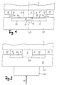
- the first coupling member 1 cannot on a machining head shown machine tool, for example a die sinking EDM machine be attached and has a substantially flat underside 2, which is extends transversely to an axis 10 coinciding with the z direction. From the Bottom 2 are four arranged crosswise and therefore in the circumferential direction equally spaced prismatic pins, of which only the one in FIG Prism pin 5 can be seen. Since all prism posts are designed in the same way, only the prism pin 5 is described in detail. He has two Opposing, flat prism surfaces 6, 8, each of which faces the axis 10 is inclined that the prism pin 5 tapers away from the bottom 2. The The inclination of the prism surfaces 6, 8 to the axis 10 is relatively small and therefore out Figure 1 is difficult to see.
- the free end face 4 of the prism pin 5 is a ground z reference surface formed, which extends exactly perpendicular to the axis 10. It it goes without saying that the free end faces of the rest are not shown Prism pins are also designed as z-reference surfaces in such a way that all z-reference surfaces exactly in a common, perpendicular to axis 10 extending plane.
- the coupling member 1 is crosswise with four arranged z-reference surfaces.
- the second, movable coupling member 20 does not bear on its underside 21 shown workpiece, which is to be machined in the machine tool.
- its top 9 which is used to prepare the tightening of the two Coupling elements 1, 20 facing the underside 2 of the first coupling element 1 is aligned on the prism pins 5 four grooves, of which in the figures only the groove 24 is executed and subsequently representative of the other grooves is described.
- the groove 24 is formed by two opposite, equally long and equally wide lips 26, 28 partially covered, which in the Form the claims mentioned elastic elements and here from the body of second coupling member 20 cut out (EP-A-255 042) or as a single Spring steel segments welded onto a blank for the coupling member 20 could be.
- the lips 26, 28 are in any case independent of one another axially elastic and leave between them a central groove opening 25, the Width is greater than the width of the prism pin 5 on the underside 2 distal end of the prism surfaces 6, 8 and smaller than the width of the Prism pin 5 at its transition to the bottom 2. As shown Cross section of each of the lips 26, 28 a rectangular. The outer top free Edges of the lips 26, 28 can adapt to the inclination of the prism surfaces 6, 8 be slightly chamfered.
- the tensioning device pulls the two coupling members 1, 20 towards each other until the z reference surface 4 on the z counter reference surface 29 lies on.
- the coupling member 20 is relative to the z-direction Coupling member 1 clearly positioned.
- the axially elastic elements from two opposite upright ones Legs 76, 78 of an insert 70 that is U-shaped in cross section and that fits into a groove 64 of the coupling member 60 used and on a central elevation 62 from the Groove base 63 is firmly anchored and its bottom 72, for example Spring steel can exist.
- the two legs 76, 78 lie on the respective adjacent vertical groove flank 66, 68 and are by virtue of the Legs 76, 78 adjoining and spaced apart over the groove base 63 extending bottom portions 71, 73 axially movable.
- the floor 72 has a central round or elongated opening through which a protrusion 65 extends vertically upwards.
- a z-counter reference surface 69 formed when clamping against a z-reference surface 59 rests on the free end face of the prism pin 52.
- the one out the free underside 51 of the first coupling member 50 protruding prism pins 52 is on its two opposite sides with a prism surface 54, 56 provided.
- the prism pin 52 When clamped together, the prism pin 52 penetrates the opening of the insert 70 and thus into the groove 64 until the free edges of the legs 76, 78 die Contact prism surfaces 54, 56 and thereby align the Obtain coupling elements 50 and 60 in the x-y plane. With further penetration of the prism pin 52 in the insert 70 wedge the legs 76, 78 to the Prism surfaces 54, 56, so that the legs 76, 78 from the prism pin 54 below Bending the bottom portions 71, 73 are carried inward until its z reference surface 59 is seated on the z counter reference surface 69.
- the axial arrangement of the additional z references in Relation to the original z references should be such that the mentioned Distance between the z reference surface 4 and the z counter reference surface 29 by or a few ⁇ m larger than the distance between one of the additional z reference surfaces 31, 33 and the respectively associated additional z counter reference surfaces 35, 37.
- the additional z reference surfaces 31, 33 in contact with the associated additional z counter reference surfaces 35, 37, whereas between the z reference surface 4 and the z counter reference surface 29 the difference in distance of one or a few ⁇ m remains. Only when the axial external load 40 exceeds a certain value, the z reference surface also come 4 and the z counter reference surface 29 for mutual contact.
- This embodiment of the invention has the advantage that any Upset deformation of the posts 32, 34 under the influence of high load 40 without Influence on the alignment of the coupling member 20 in the x-y plane remains.
- the invention can also be used in a tensioning device which is known from DE-U-295 21 030 is known.
- One of the lips 26, 28 is then omitted and the groove 24 is open the lip-free side is limited by a fixed edge or a fixed groove flank.
- the prism pin 5 then only has that on the lip assigned side a single prism surface, during which emerges from the Protrusion with a groove base and provided with the z counter reference surface merges into the groove flank on one side.
- the surface 54 axially parallel and the associated groove flank 66 prismatic, i.e. to be inclined to the clamping direction, then the axially elastic base section 71 with the axial leg 76 on Coupling member 50 is attached so that leg 76 on surface 54 rests axially elastic.
Landscapes
- Engineering & Computer Science (AREA)
- Mechanical Engineering (AREA)
- Chemical & Material Sciences (AREA)
- Chemical Kinetics & Catalysis (AREA)
- Electrochemistry (AREA)
- Jigs For Machine Tools (AREA)
- Clamps And Clips (AREA)
- Details Of Cutting Devices (AREA)
- Insertion Pins And Rivets (AREA)
- Connection Of Plates (AREA)
Applications Claiming Priority (2)
| Application Number | Priority Date | Filing Date | Title |
|---|---|---|---|
| DE19857913A DE19857913C2 (de) | 1998-12-16 | 1998-12-16 | Kupplungsvorrichtung |
| DE19857913 | 1998-12-16 |
Publications (3)
| Publication Number | Publication Date |
|---|---|
| EP1013375A2 true EP1013375A2 (fr) | 2000-06-28 |
| EP1013375A3 EP1013375A3 (fr) | 2001-01-31 |
| EP1013375B1 EP1013375B1 (fr) | 2003-10-29 |
Family
ID=7891199
Family Applications (1)
| Application Number | Title | Priority Date | Filing Date |
|---|---|---|---|
| EP99124907A Expired - Lifetime EP1013375B1 (fr) | 1998-12-16 | 1999-12-14 | Dispositif d'accouplement avec deux parties d'accouplement, et un dispositif de serrage |
Country Status (6)
| Country | Link |
|---|---|
| US (1) | US6336767B1 (fr) |
| EP (1) | EP1013375B1 (fr) |
| JP (1) | JP4550196B2 (fr) |
| CN (1) | CN1108229C (fr) |
| DE (2) | DE19857913C2 (fr) |
| TW (1) | TW444105B (fr) |
Cited By (2)
| Publication number | Priority date | Publication date | Assignee | Title |
|---|---|---|---|---|
| EP2246148A1 (fr) * | 2009-04-28 | 2010-11-03 | Kabushiki Kaisha Honma Seisakusho | Appareil de positionnement pour le positionnement d'un objet, dispositif de rétention et son attache |
| TWI608895B (zh) * | 2015-11-09 | 2017-12-21 | Cherng Jin Technology Co Ltd | Fixture mold base |
Families Citing this family (38)
| Publication number | Priority date | Publication date | Assignee | Title |
|---|---|---|---|---|
| DE19858159C2 (de) * | 1998-12-16 | 2003-07-10 | System 3R Internat Ab Vaelling | Kupplungsvorrichtung |
| US7378611B2 (en) * | 2004-03-19 | 2008-05-27 | General Electric Company | Apparatus and method for electrical discharge machining |
| EP1629920A1 (fr) * | 2004-08-26 | 2006-03-01 | System 3R International AB | Dispositif de serrage d'un outil dans une machine d'usinage, en particulier pour une machine d'usinage par électroérosion. |
| DE502005004878D1 (de) * | 2005-03-24 | 2008-09-11 | 3R Syst Int Ab | Kupplungsvorrichtung mit elastischen Bereichen zur X-Y-Ausrichtung |
| EP1741511B1 (fr) * | 2005-07-09 | 2008-03-05 | System 3R International AB | Dispositif de serrage pour un outil ou une pièce à travailler |
| TW200732083A (en) * | 2006-01-30 | 2007-09-01 | Tool Internat Ag F | Clamping apparatus |
| US8113497B2 (en) * | 2007-05-09 | 2012-02-14 | Kell Tech, Inc. | Clamping fixture with adjustable assemblies |
| US9812684B2 (en) | 2010-11-09 | 2017-11-07 | GM Global Technology Operations LLC | Using elastic averaging for alignment of battery stack, fuel cell stack, or other vehicle assembly |
| US9618026B2 (en) | 2012-08-06 | 2017-04-11 | GM Global Technology Operations LLC | Semi-circular alignment features of an elastic averaging alignment system |
| US9463538B2 (en) | 2012-08-13 | 2016-10-11 | GM Global Technology Operations LLC | Alignment system and method thereof |
| CN103072031B (zh) * | 2013-01-24 | 2015-01-28 | 宁波志清实业有限公司 | 用于加工h型锁闭阀阀体的工装夹具 |
| US9556890B2 (en) | 2013-01-31 | 2017-01-31 | GM Global Technology Operations LLC | Elastic alignment assembly for aligning mated components and method of reducing positional variation |
| US9388838B2 (en) | 2013-04-04 | 2016-07-12 | GM Global Technology Operations LLC | Elastic retaining assembly for matable components and method of assembling |
| US9447840B2 (en) | 2013-06-11 | 2016-09-20 | GM Global Technology Operations LLC | Elastically deformable energy management assembly and method of managing energy absorption |
| CN104275608B (zh) * | 2013-07-03 | 2017-03-01 | 晟进科技股份有限公司 | 夹具定位板 |
| US9488205B2 (en) | 2013-07-12 | 2016-11-08 | GM Global Technology Operations LLC | Alignment arrangement for mated components and method |
| US9303667B2 (en) | 2013-07-18 | 2016-04-05 | Gm Global Technology Operations, Llc | Lobular elastic tube alignment system for providing precise four-way alignment of components |
| US9863454B2 (en) | 2013-08-07 | 2018-01-09 | GM Global Technology Operations LLC | Alignment system for providing precise alignment and retention of components of a sealable compartment |
| US9458876B2 (en) | 2013-08-28 | 2016-10-04 | GM Global Technology Operations LLC | Elastically deformable alignment fastener and system |
| US9463831B2 (en) | 2013-09-09 | 2016-10-11 | GM Global Technology Operations LLC | Elastic tube alignment and fastening system for providing precise alignment and fastening of components |
| US9457845B2 (en) | 2013-10-02 | 2016-10-04 | GM Global Technology Operations LLC | Lobular elastic tube alignment and retention system for providing precise alignment of components |
| US9511802B2 (en) | 2013-10-03 | 2016-12-06 | GM Global Technology Operations LLC | Elastically averaged alignment systems and methods |
| US9669774B2 (en) | 2013-10-11 | 2017-06-06 | GM Global Technology Operations LLC | Reconfigurable vehicle interior assembly |
| US9481317B2 (en) | 2013-11-15 | 2016-11-01 | GM Global Technology Operations LLC | Elastically deformable clip and method |
| US9447806B2 (en) * | 2013-12-12 | 2016-09-20 | GM Global Technology Operations LLC | Self-retaining alignment system for providing precise alignment and retention of components |
| US9428123B2 (en) | 2013-12-12 | 2016-08-30 | GM Global Technology Operations LLC | Alignment and retention system for a flexible assembly |
| US9599279B2 (en) | 2013-12-19 | 2017-03-21 | GM Global Technology Operations LLC | Elastically deformable module installation assembly |
| US9446722B2 (en) | 2013-12-19 | 2016-09-20 | GM Global Technology Operations LLC | Elastic averaging alignment member |
| US9541113B2 (en) | 2014-01-09 | 2017-01-10 | GM Global Technology Operations LLC | Elastically averaged alignment systems and methods |
| US9428046B2 (en) | 2014-04-02 | 2016-08-30 | GM Global Technology Operations LLC | Alignment and retention system for laterally slideably engageable mating components |
| US9657807B2 (en) | 2014-04-23 | 2017-05-23 | GM Global Technology Operations LLC | System for elastically averaging assembly of components |
| US9429176B2 (en) | 2014-06-30 | 2016-08-30 | GM Global Technology Operations LLC | Elastically averaged alignment systems and methods |
| US9758110B2 (en) | 2015-01-12 | 2017-09-12 | GM Global Technology Operations LLC | Coupling system |
| US10107319B2 (en) | 2015-03-02 | 2018-10-23 | GM Global Technology Operations LLC | Elastically averaged alignment systems and methods |
| US9604330B2 (en) * | 2015-03-12 | 2017-03-28 | Jia Sin Precision Co., Ltd. | Positioning block structure for machining fixture |
| JP6430329B2 (ja) * | 2015-05-13 | 2018-11-28 | Towa株式会社 | 切断装置及び切断方法 |
| CN104924355B (zh) * | 2015-05-25 | 2017-03-08 | 杭州电子科技大学 | 一种双摆角超声切割装置及方法 |
| CN105928365B (zh) * | 2016-05-05 | 2017-12-12 | 武汉拓材科技有限公司 | 一种用于高纯材料制备的石英器皿渗碳装置及方法 |
Family Cites Families (15)
| Publication number | Priority date | Publication date | Assignee | Title |
|---|---|---|---|---|
| US2309713A (en) * | 1940-08-07 | 1943-02-02 | American Brake Shoe & Foundry | Hammer for centrifugal devices and the like |
| JPS5928738Y2 (ja) * | 1979-02-06 | 1984-08-18 | 株式会社ソディック | 電極取付装置 |
| CH675150A5 (en) * | 1982-10-18 | 1990-08-31 | Erowa Ag | Clutch for e.g. machine tool |
| DE3625608A1 (de) * | 1986-07-29 | 1988-04-21 | 3R Management Ab | Spannvorrichtung fuer ein werkzeug an einer werkzeugmaschine, insbesondere einer senkerodiermaschine |
| US4855558A (en) * | 1986-07-29 | 1989-08-08 | System 3R International Ab | Clamping device for a tool at a machine tool, particularly at a die sinking electric discharge machine |
| CH671356A5 (fr) * | 1986-10-10 | 1989-08-31 | Buechler B Set Ag | |
| US5154559A (en) * | 1991-07-25 | 1992-10-13 | Illinois Tool Works Inc. | Captivating a fastener to a workpiece |
| DE4426551A1 (de) * | 1994-07-27 | 1996-02-01 | Campro Tooling Ab | Spannvorrichtung |
| DE4444241C2 (de) | 1994-12-13 | 1998-09-03 | 3R Syst Int Ab | Spannvorrichtung |
| DE29521030U1 (de) * | 1994-12-13 | 1996-09-05 | Campro Tooling AB, Taeby | Spannvorrichtung |
| EP0818270B1 (fr) * | 1996-06-17 | 2001-11-14 | Certa AG | Dispositif de serrage et dispositif pour le blocage indexé d'une pièce de travail ou d'un outil |
| US6123339A (en) * | 1997-05-20 | 2000-09-26 | Daiso Corporation | Non-gasket sealing structure |
| CH693133A5 (de) * | 1997-08-21 | 2003-03-14 | Mecatool Ag | Kupplungsanordnung für eine Bearbeitungseinrichtung. |
| DE19849445A1 (de) * | 1998-10-27 | 2000-05-04 | System 3R International Ab Vae | Werkzeughalter für eine Werkzeugmaschine |
| DE19858159C2 (de) * | 1998-12-16 | 2003-07-10 | System 3R Internat Ab Vaelling | Kupplungsvorrichtung |
-
1998
- 1998-12-16 DE DE19857913A patent/DE19857913C2/de not_active Expired - Fee Related
-
1999
- 1999-12-14 DE DE59907534T patent/DE59907534D1/de not_active Expired - Lifetime
- 1999-12-14 EP EP99124907A patent/EP1013375B1/fr not_active Expired - Lifetime
- 1999-12-16 US US09/465,011 patent/US6336767B1/en not_active Expired - Lifetime
- 1999-12-16 CN CN99126756A patent/CN1108229C/zh not_active Expired - Fee Related
- 1999-12-16 JP JP35742799A patent/JP4550196B2/ja not_active Expired - Fee Related
-
2000
- 2000-01-07 TW TW089100184A patent/TW444105B/zh not_active IP Right Cessation
Cited By (3)
| Publication number | Priority date | Publication date | Assignee | Title |
|---|---|---|---|---|
| EP2246148A1 (fr) * | 2009-04-28 | 2010-11-03 | Kabushiki Kaisha Honma Seisakusho | Appareil de positionnement pour le positionnement d'un objet, dispositif de rétention et son attache |
| US8757920B2 (en) | 2009-04-28 | 2014-06-24 | Kabushiki Kaisha Honma Seisakusho | Positioning apparatus for positioning object, retainer and fastener thereof |
| TWI608895B (zh) * | 2015-11-09 | 2017-12-21 | Cherng Jin Technology Co Ltd | Fixture mold base |
Also Published As
| Publication number | Publication date |
|---|---|
| JP4550196B2 (ja) | 2010-09-22 |
| DE19857913A1 (de) | 2000-07-06 |
| DE19857913C2 (de) | 2003-10-02 |
| JP2000176775A (ja) | 2000-06-27 |
| DE59907534D1 (de) | 2003-12-04 |
| TW444105B (en) | 2001-07-01 |
| CN1258588A (zh) | 2000-07-05 |
| EP1013375B1 (fr) | 2003-10-29 |
| CN1108229C (zh) | 2003-05-14 |
| EP1013375A3 (fr) | 2001-01-31 |
| US6336767B1 (en) | 2002-01-08 |
Similar Documents
| Publication | Publication Date | Title |
|---|---|---|
| EP1013375B1 (fr) | Dispositif d'accouplement avec deux parties d'accouplement, et un dispositif de serrage | |
| WO1999065643A1 (fr) | Procede pour assembler deux elements de maniere detachable et systemes d'assemblage pour mettre ledit procede en oeuvre | |
| DE69400349T2 (de) | Oberflächenverbinder | |
| EP1955816A2 (fr) | Dispositif de serrage | |
| DD297099B5 (de) | Vorrichtung zur Verbindung zweier Werkzeugteile | |
| EP1016498B1 (fr) | Dispositif d'accouplement avec deux parties d'accouplement, et un dispositif de serrage. | |
| DE2633403A1 (de) | Daempfungspuffer | |
| WO2002030659A1 (fr) | Transmission par courroie trapezoidale | |
| EP1754030B1 (fr) | Securite antisurcharge pour element dynamometrique | |
| EP2783795B1 (fr) | Mâchoire de serrage | |
| WO2009021722A1 (fr) | Élément d'accouplement pour un accouplement entraîneur, et procédé de fabrication | |
| EP1311355B1 (fr) | Dispositif de serrage pour un outil de formage, en particulier pour une presse plieuse | |
| EP0362753A1 (fr) | Dispositif de fixation | |
| DE69017214T2 (de) | Verfahren und vorrichtung zum ausgleichen der verformungen des rahmens einer exzenterpresse. | |
| EP0997220A2 (fr) | Porte-outil pour machine-outil | |
| DE2117245A1 (en) | Laminated press tool | |
| EP2626173B1 (fr) | Griffe de serrage pour un dispositif de serrage | |
| DE3837444C1 (en) | Device for mutual clamping of two objects | |
| AT17990U1 (de) | Eingriffselement und Spannsystem | |
| DE102022109309B3 (de) | Niederzugspanner | |
| DE102006007771B4 (de) | Vorrichtung mit Führung und herausnehmbaren taillierten Nocken | |
| DE102012209863B3 (de) | Führungsschiene für eine Linearführung | |
| AT521128B1 (de) | Zungenschiene | |
| DE29916856U1 (de) | Spannkeilvorrichtung | |
| DE20303909U1 (de) | Spannkeilvorrichtung |
Legal Events
| Date | Code | Title | Description |
|---|---|---|---|
| PUAI | Public reference made under article 153(3) epc to a published international application that has entered the european phase |
Free format text: ORIGINAL CODE: 0009012 |
|
| AK | Designated contracting states |
Kind code of ref document: A2 Designated state(s): CH DE FR GB IT LI SE |
|
| AX | Request for extension of the european patent |
Free format text: AL;LT;LV;MK;RO;SI |
|
| PUAL | Search report despatched |
Free format text: ORIGINAL CODE: 0009013 |
|
| AK | Designated contracting states |
Kind code of ref document: A3 Designated state(s): AT BE CH CY DE DK ES FI FR GB GR IE IT LI LU MC NL PT SE |
|
| AX | Request for extension of the european patent |
Free format text: AL;LT;LV;MK;RO;SI |
|
| 17P | Request for examination filed |
Effective date: 20010426 |
|
| AKX | Designation fees paid |
Free format text: CH DE FR GB IT LI SE |
|
| 17Q | First examination report despatched |
Effective date: 20030312 |
|
| GRAH | Despatch of communication of intention to grant a patent |
Free format text: ORIGINAL CODE: EPIDOS IGRA |
|
| GRAS | Grant fee paid |
Free format text: ORIGINAL CODE: EPIDOSNIGR3 |
|
| GRAA | (expected) grant |
Free format text: ORIGINAL CODE: 0009210 |
|
| AK | Designated contracting states |
Kind code of ref document: B1 Designated state(s): CH DE FR GB IT LI SE |
|
| REG | Reference to a national code |
Ref country code: GB Ref legal event code: FG4D Free format text: NOT ENGLISH |
|
| REG | Reference to a national code |
Ref country code: CH Ref legal event code: EP |
|
| REG | Reference to a national code |
Ref country code: SE Ref legal event code: TRGR |
|
| REG | Reference to a national code |
Ref country code: CH Ref legal event code: NV Representative=s name: ISLER & PEDRAZZINI AG |
|
| REF | Corresponds to: |
Ref document number: 59907534 Country of ref document: DE Date of ref document: 20031204 Kind code of ref document: P |
|
| GBT | Gb: translation of ep patent filed (gb section 77(6)(a)/1977) |
Effective date: 20031217 |
|
| ET | Fr: translation filed | ||
| PLBE | No opposition filed within time limit |
Free format text: ORIGINAL CODE: 0009261 |
|
| STAA | Information on the status of an ep patent application or granted ep patent |
Free format text: STATUS: NO OPPOSITION FILED WITHIN TIME LIMIT |
|
| 26N | No opposition filed |
Effective date: 20040730 |
|
| REG | Reference to a national code |
Ref country code: CH Ref legal event code: PCAR Free format text: ISLER & PEDRAZZINI AG;POSTFACH 1772;8027 ZUERICH (CH) |
|
| PGFP | Annual fee paid to national office [announced via postgrant information from national office to epo] |
Ref country code: IT Payment date: 20071220 Year of fee payment: 9 |
|
| PGFP | Annual fee paid to national office [announced via postgrant information from national office to epo] |
Ref country code: GB Payment date: 20071218 Year of fee payment: 9 |
|
| PGFP | Annual fee paid to national office [announced via postgrant information from national office to epo] |
Ref country code: FR Payment date: 20071217 Year of fee payment: 9 |
|
| GBPC | Gb: european patent ceased through non-payment of renewal fee |
Effective date: 20081214 |
|
| REG | Reference to a national code |
Ref country code: FR Ref legal event code: ST Effective date: 20090831 |
|
| PG25 | Lapsed in a contracting state [announced via postgrant information from national office to epo] |
Ref country code: GB Free format text: LAPSE BECAUSE OF NON-PAYMENT OF DUE FEES Effective date: 20081214 |
|
| PG25 | Lapsed in a contracting state [announced via postgrant information from national office to epo] |
Ref country code: FR Free format text: LAPSE BECAUSE OF NON-PAYMENT OF DUE FEES Effective date: 20081231 |
|
| PG25 | Lapsed in a contracting state [announced via postgrant information from national office to epo] |
Ref country code: IT Free format text: LAPSE BECAUSE OF NON-PAYMENT OF DUE FEES Effective date: 20081214 |
|
| PGFP | Annual fee paid to national office [announced via postgrant information from national office to epo] |
Ref country code: DE Payment date: 20151210 Year of fee payment: 17 Ref country code: CH Payment date: 20151221 Year of fee payment: 17 |
|
| PGFP | Annual fee paid to national office [announced via postgrant information from national office to epo] |
Ref country code: SE Payment date: 20151221 Year of fee payment: 17 |
|
| REG | Reference to a national code |
Ref country code: DE Ref legal event code: R119 Ref document number: 59907534 Country of ref document: DE |
|
| REG | Reference to a national code |
Ref country code: CH Ref legal event code: PL |
|
| REG | Reference to a national code |
Ref country code: SE Ref legal event code: EUG |
|
| PG25 | Lapsed in a contracting state [announced via postgrant information from national office to epo] |
Ref country code: SE Free format text: LAPSE BECAUSE OF NON-PAYMENT OF DUE FEES Effective date: 20161215 |
|
| PG25 | Lapsed in a contracting state [announced via postgrant information from national office to epo] |
Ref country code: CH Free format text: LAPSE BECAUSE OF NON-PAYMENT OF DUE FEES Effective date: 20161231 Ref country code: LI Free format text: LAPSE BECAUSE OF NON-PAYMENT OF DUE FEES Effective date: 20161231 |
|
| PG25 | Lapsed in a contracting state [announced via postgrant information from national office to epo] |
Ref country code: DE Free format text: LAPSE BECAUSE OF NON-PAYMENT OF DUE FEES Effective date: 20170701 |