EP1013377B1 - Angetriebenes Werkzeug - Google Patents
Angetriebenes Werkzeug Download PDFInfo
- Publication number
- EP1013377B1 EP1013377B1 EP99308945A EP99308945A EP1013377B1 EP 1013377 B1 EP1013377 B1 EP 1013377B1 EP 99308945 A EP99308945 A EP 99308945A EP 99308945 A EP99308945 A EP 99308945A EP 1013377 B1 EP1013377 B1 EP 1013377B1
- Authority
- EP
- European Patent Office
- Prior art keywords
- cartridge
- housing
- power tool
- drive
- motor
- Prior art date
- Legal status (The legal status is an assumption and is not a legal conclusion. Google has not performed a legal analysis and makes no representation as to the accuracy of the status listed.)
- Expired - Lifetime
Links
- 230000008878 coupling Effects 0.000 claims description 7
- 238000010168 coupling process Methods 0.000 claims description 7
- 238000005859 coupling reaction Methods 0.000 claims description 7
- 230000007246 mechanism Effects 0.000 claims description 6
- 208000019300 CLIPPERS Diseases 0.000 description 2
- 230000005540 biological transmission Effects 0.000 description 2
- 208000021930 chronic lymphocytic inflammation with pontine perivascular enhancement responsive to steroids Diseases 0.000 description 2
- 230000033001 locomotion Effects 0.000 description 2
- 238000000576 coating method Methods 0.000 description 1
- 238000010276 construction Methods 0.000 description 1
- 239000000428 dust Substances 0.000 description 1
- 238000000605 extraction Methods 0.000 description 1
- 229910000078 germane Inorganic materials 0.000 description 1
- 238000010348 incorporation Methods 0.000 description 1
- 230000013011 mating Effects 0.000 description 1
- 238000005498 polishing Methods 0.000 description 1
Images


Classifications
-
- B—PERFORMING OPERATIONS; TRANSPORTING
- B27—WORKING OR PRESERVING WOOD OR SIMILAR MATERIAL; NAILING OR STAPLING MACHINES IN GENERAL
- B27C—PLANING, DRILLING, MILLING, TURNING OR UNIVERSAL MACHINES FOR WOOD OR SIMILAR MATERIAL
- B27C1/00—Machines for producing flat surfaces, e.g. by rotary cutters; Equipment therefor
- B27C1/10—Hand planes equipped with power-driven cutter blocks
-
- B—PERFORMING OPERATIONS; TRANSPORTING
- B24—GRINDING; POLISHING
- B24B—MACHINES, DEVICES, OR PROCESSES FOR GRINDING OR POLISHING; DRESSING OR CONDITIONING OF ABRADING SURFACES; FEEDING OF GRINDING, POLISHING, OR LAPPING AGENTS
- B24B23/00—Portable grinding machines, e.g. hand-guided; Accessories therefor
- B24B23/06—Portable grinding machines, e.g. hand-guided; Accessories therefor with abrasive belts, e.g. with endless travelling belts; Accessories therefor
-
- B—PERFORMING OPERATIONS; TRANSPORTING
- B27—WORKING OR PRESERVING WOOD OR SIMILAR MATERIAL; NAILING OR STAPLING MACHINES IN GENERAL
- B27C—PLANING, DRILLING, MILLING, TURNING OR UNIVERSAL MACHINES FOR WOOD OR SIMILAR MATERIAL
- B27C9/00—Multi-purpose machines; Universal machines; Equipment therefor
- B27C9/02—Multi-purpose machines; Universal machines; Equipment therefor with a single working spindle
Definitions
- the present invention relates to a power tool arranged to perform a plurality of operations and in particular to a power tool which is interchangeable between the two tasks of sanding and planing a workpiece.
- a power tool is disclosed in DE-A-3 621 240, in accordance with the preamble of claim 1.
- UK patent number GB 1515390 discloses a power tool which is said to be of modular construction.
- the tool comprises a battery unit which is adapted to accept any one of a plurality of operative parts, such as a hedge clipper or a screwdriver.
- Each of the operative parts has its own motor and an arrangement for converting the output of the motor (usually a rotating spindle) into the type of drive necessary for that particular tool.
- a linear reciprocating drive is needed for the hedge clipper, whereas a low rotational velocity, high torque drive is needed for the screwdriver.
- EP-A-698449 there is disclosed a modular power tool having separate motor and drive mechanisms.
- the two mechanisms are brought into operative engagement by sliding and rotating the motor relative to the transmission.
- This device is limited in that the transmission may only be used as a drill/driver and is not able to function in any other mode.
- One aspect of the present invention is based on the recognition that the two operations of sanding and of planing a workpiece are discrete, yet clearly related. Generally planing is used to remove a larger amount of stock from a workpiece than sanding. Also, sanding is used to provide a smoother or finer finish to a workpiece than planing. Or for the removal of previously applied surface coatings.
- the present invention also, however, recognises that one of the most efficient forms of sanding is belt sanding.
- This utilises a continuous loop of sandpaper being driven around two displaced rollers, as is known in the art.
- a continuous loop of sandpaper in a modular tool (where one of the other modules is a planer - which essentially comprises only a single rotating cylinder or cutting device) could well take up a great deal of space.
- a modular tool which is able to offer modules capable of both belt sanding and planing is a difficult challenge to achieve, not least because of the different space requirements between tools to achieve each function.
- the present invention provides a power tool arranged to perform a plurality of operations, the operations including belt sanding and planing, wherein the tool comprises: a housing; a motor within the housing for providing drive to an output shaft; and a plurality of cartridges, each of which cartridges may be coupled to the housing and to the drive shaft to enable performance of a respective operation, wherein one cartridge performs belt sanding and another cartridge performs planing.
- the tool comprises: a housing; a motor within the housing for providing drive to an output shaft; and a plurality of cartridges, each of which cartridges may be coupled to the housing and to the drive shaft to enable performance of a respective operation, wherein one cartridge performs belt sanding and another cartridge performs planing.
- each cartridge includes a recess for coupling with the drive shaft.
- the drive shaft may rotate under the drive of the motor.
- the motor may be coupled directly to the drive shaft.
- each cartridge may include an interlock mechanism co-operable with the interlock formed on the housing.
- each cartridge may be presented to the body in a predetermined orientation in order to couple the cartridge with the body.
- a housing for a power tool is shown generally as 2.
- the housing comprises a handle (4) and a main body (6) in use of the device a user may hold both the main body (6) and the handle (4) in order to guide the power tool against a workpiece.
- the underside portion (8) of the housing is shaped to accept a cartridge (described further below) presented thereto.
- a cartridge (described further below) presented thereto.
- the underside (8) defines an abutment (10) formed by the two side walls (12 and 14).
- the side wall (12) is formed an interlock member (16) for co-operable engagement with a cartridge presented to the housing (2), as will be described below.
- the side wall (12) also includes a recess (18) for stock removal/ dust extraction when the power tool is in use.
- the motor is a conventional electric motor and is described with reference to Figures 7 and 9 in more detail.
- the motor is coupled to an output shaft (20) for providing drive to a cartridge presented thereto.
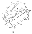
- a cartridge shown generally as 22, has been presented to the main body (6) for coupling thereto.
- the cartridge comprises a belt sander module for incorporation with the main body (6) so that the entire tool (2) (when the main body (6) and the cartridge (22) are coupled operatively together) operates as a belt sander.
- the cartridge (22) includes a first cylinder (24) and a further cylinder (26).
- the cylinders (24 and 26) are surrounded by a continuous loop of sandpaper (28) thereby forming a belt sander.
- the cylinders (24, 26) need to be resiliently biassed so as to keep the loop of sandpaper (28) under sufficient tension so that it may perform efficaciously as a belt sander.
- the cartridge (22) includes a further interlock member (30) which is co-operable with the interlock member (16) on the main body (6) so as to retain the cartridge (22) in rigid engagement with the main body (6) in operation of the tool.
- the cylinder (24) includes a recess (not shown in Figure 2) for co-operating with the output shaft (20).
- the first operation necessary to couple the cartridge (22) to the body (6) is that of mating the recess in the cylinder (24) with the output shaft (20). This is shown from the large arrow "A” in Figure 2.
- the cartridge (22) is then pivoted about the axis of the cylinder (24) (because the cylinder (24) is now operatively coupled to the output shaft (20)) and the interlock members (16 and 30) are coupled together. This pivoting movement is shown by the arrow "B" in the figure.
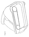
- Figure 3 shows the cartridge (22) when operatively coupled to the main body (6).
- the main body (6) includes an arcuate portion (32).
- the cartridge (22) includes a correspondingly shaped arcuate portion (34).
- the purpose of the arcuate portions (32, 34) is to ensure unimpeded motion when pivoting the cartridge (22) to its final operative position.
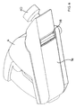
- FIG. 5 and 6 there is shown a power tool whose main body (6) is operatively coupled to a cartridge (36).
- the cartridge (36) is an alternative to that (22) with reference to Figures 1 to 4.
- the cartridge (36) is that of a planer, rather than a belt sander.
- the cartridge (36) includes a cylinder (38) which, in common with the cylinder (24) has a recess formed therein to mate with the output shaft (20).
- the operation of coupling the cartridge (36) to the main body (6) is exactly the same as that with respect to cartridge (24).
- the main differences between the two cartridges (22 and 36) is that the cartridge (22) is a belt sander whereas the cartridge (36) is a planer. This means, that the cartridge (36) does not require a rear roller and therefore only cylinder (38) is present.
- the cylinder (38) is that of a planer and therefore includes the common characteristics of the planer, such as a radial projection (cutting blade) and depth of cut adjustment means as shown by reference numeral 40.
- a radial projection cutting blade
- depth of cut adjustment means as shown by reference numeral 40.
- the power tool (2) has a main body (6) which can be operatively coupled to any one of a plurality of cartridges, of which two illustrative embodiments (22, 36) are shown. It will be further apparent that further cartridges are possible and these are clearly within the scope of those skilled in the art, although they are not described herein. For example, an alternative cartridge could achieve orbital sanding or polishing tasks or the like.
- the cartridge (22) is operatively coupled to a motor (42) by a belt drive mechanism (44).
- the output of the motor (42) is coupled by rotating shaft (46) to a drive cog (48).
- the drive cog (48) rotates at around 30,000 revolutions per minute.
- the belt drive (44) is coupled to a driven cog (50) which is coupled to the output shaft (20) via a drive shaft (52).
- the driven cog (50) has generally a greater number of teeth than the drive cog (48). Therefore there is a speed reduction between the drive cog (48) and driven cog (50) which results in the driven cog (50) (and therefore the drive shaft (52) and therefore the output shaft (20)) rotating at around 16,000 revolutions per minute.
- the belt sander cartridge (28) needs to have the drive roller (24) rotating in the opposite sense to that of the planer cylinder (38) of the planer cartridge (36).
- Figure 8 shows a section taken along the line X-X of the cylinder (24) in Figure 7.
- the output shaft (20) terminates in a sun gear (54) which is at the centre of the cylinder (24).
- the sun gear rotates in a first sense, say, clockwise as shown in Figure 8.
- a plurality of planet gears (56), in this example 3 are fixed in position relative to the sun gear (54). Although the planet gears are fixed, they are free to rotate about their respective central axis. This means, that when the sun gear (54) rotates in a clockwise position, each planet gear (56) rotates about its own axis in an anti-clockwise sense.
- a rotatable ring gear (58) Surrounding the planet gears (56) is a rotatable ring gear (58) which is rigidly coupled to the outer periphery of the cylinder (24).
- the inner periphery of the ring gear (58) carries a plurality of teeth which co-operatively engage with the gearing teeth of the planet gears (56). This means, therefore, that the ring gear (58) (and therefore the cylinder (24)) rotate in an anti-clockwise sense as shown by the outermost arrow of Figure 8.
- FIG 9 there is shown a representation of the planer cartridge (36).
- similar components are numbered correspondingly with those of Figure 7, because the motor (42) and the belt drive (44) and the output shaft (20) are all common with that of the housing (6) of Figure 7. Because of this, further description of the mechanism up to and including the output shaft (20) will not be given herein.
- any suitable cartridge may be coupled with the body (6) in order to achieve the desired operative result.
Landscapes
- Life Sciences & Earth Sciences (AREA)
- Engineering & Computer Science (AREA)
- Mechanical Engineering (AREA)
- Wood Science & Technology (AREA)
- Forests & Forestry (AREA)
- Finish Polishing, Edge Sharpening, And Grinding By Specific Grinding Devices (AREA)
- Cutting Tools, Boring Holders, And Turrets (AREA)
- Braking Systems And Boosters (AREA)
- Valve Device For Special Equipments (AREA)
- Devices For Conveying Motion By Means Of Endless Flexible Members (AREA)
- Portable Nailing Machines And Staplers (AREA)
- Eye Examination Apparatus (AREA)
- Percussive Tools And Related Accessories (AREA)
Claims (7)
- Angetriebenes Werkzeug ausgebildet zur Durchführung mehrerer Vorgänge einschließlich Bandschleifen und Hobeln, mit einem Gehäuse (2),
einem im Gehäuse vorgesehenen Motor (42) für den Antrieb einer Abgabewelle (20) und
gekennzeichnet durch mehrere Kassetten (22, 36), von denen jede mit dem Gehäuse und der Antriebswelle gekoppelt werden kann, um die Durchführung eines jeweiligen Vorgangs zu ermöglichen, wobei eine Kassette Bandschleifen und eine andere Kassette Hobeln durchführt. - Angetriebenes Werkzeug nach Anspruch 1, bei dem die Antriebswelle aus dem Gehäuse vorsteht und jede Kassette eine Aussparung zur Kopplung mit der Antriebswelle hat.
- Angetriebenes Werkzeug nach Anspruch 1 oder 2, bei dem sich die Antriebswelle unter dem Antrieb des Motors dreht.
- Angetriebenes Werkzeug nach einem der vorhergehenden Ansprüche, bei dem der Motor direkt mit der Antriebswelle gekoppelt ist.
- Angetriebenes Werkzeug nach einem der vorhergehenden Ansprüche mit einer am Gehäuse ausgebildeten Verriegelung (16) zur Halterung einer zur Kopplung mit dem Gehäuse zugeführten Kassette.
- Angetriebenes Werkzeug nach Anspruch 5, bei dem jede Kassette einen Verriegelungsmechanismus (30) aufweist, der mit der am Gehäuse (2) ausgebildeten verriegelung (16) zusammenarbeiten kann.
- Angetriebenes Werkzeug nach einem der vorhergehenden Ansprüche, bei dem jede Kassette dem Körper in einer vorgegebenen Ausrichtung zugeführt werden muss, um sie mit dem Körper zu koppeln.
Applications Claiming Priority (2)
| Application Number | Priority Date | Filing Date | Title |
|---|---|---|---|
| GB9828579 | 1998-12-23 | ||
| GBGB9828579.4A GB9828579D0 (en) | 1998-12-23 | 1998-12-23 | Power tool |
Publications (3)
| Publication Number | Publication Date |
|---|---|
| EP1013377A2 EP1013377A2 (de) | 2000-06-28 |
| EP1013377A3 EP1013377A3 (de) | 2004-04-14 |
| EP1013377B1 true EP1013377B1 (de) | 2005-04-20 |
Family
ID=10844991
Family Applications (1)
| Application Number | Title | Priority Date | Filing Date |
|---|---|---|---|
| EP99308945A Expired - Lifetime EP1013377B1 (de) | 1998-12-23 | 1999-11-10 | Angetriebenes Werkzeug |
Country Status (4)
| Country | Link |
|---|---|
| EP (1) | EP1013377B1 (de) |
| AT (1) | ATE293525T1 (de) |
| DE (1) | DE69924820T2 (de) |
| GB (1) | GB9828579D0 (de) |
Families Citing this family (2)
| Publication number | Priority date | Publication date | Assignee | Title |
|---|---|---|---|---|
| AU2002953315A0 (en) * | 2002-12-13 | 2003-01-09 | Gmca Pty Ltd | Planer |
| US12589518B2 (en) | 2022-04-25 | 2026-03-31 | Milwaukee Electric Tool Corporation | Hand-held planning tool |
Family Cites Families (5)
| Publication number | Priority date | Publication date | Assignee | Title |
|---|---|---|---|---|
| DE7521237U (de) * | 1974-08-23 | 1975-11-13 | The Black And Decker Manufacturing Co | Batteriegetriebenes vielzweckgeraet insbesondere grasschere bohrmaschine u.a. |
| CA1078709A (en) * | 1978-05-24 | 1980-06-03 | Mustafa Fehric | Multiple purpose woodworking structure |
| US4566511A (en) * | 1984-05-11 | 1986-01-28 | Robinson James L | Sander attachment for rotary power saw |
| DE3621240A1 (de) * | 1986-06-25 | 1988-01-07 | Festo Kg | Handwerkzeugmaschine |
| ES2194044T3 (es) * | 1994-07-26 | 2003-11-16 | Black & Decker Inc | Herramienta motorizada con sistema de impulsion modular y metodo de montaje del sistema de impulsion modular. |
-
1998
- 1998-12-23 GB GBGB9828579.4A patent/GB9828579D0/en not_active Ceased
-
1999
- 1999-11-10 DE DE69924820T patent/DE69924820T2/de not_active Expired - Fee Related
- 1999-11-10 EP EP99308945A patent/EP1013377B1/de not_active Expired - Lifetime
- 1999-11-10 AT AT99308945T patent/ATE293525T1/de not_active IP Right Cessation
Also Published As
| Publication number | Publication date |
|---|---|
| GB9828579D0 (en) | 1999-02-17 |
| ATE293525T1 (de) | 2005-05-15 |
| EP1013377A3 (de) | 2004-04-14 |
| EP1013377A2 (de) | 2000-06-28 |
| DE69924820D1 (de) | 2005-05-25 |
| DE69924820T2 (de) | 2006-01-26 |
Similar Documents
| Publication | Publication Date | Title |
|---|---|---|
| EP0616565B1 (de) | Kraftwerkzeug | |
| US7134508B2 (en) | Rotary to reciprocating motion conversion attachment for a power rotary hand tool | |
| US6306024B1 (en) | Orbital tool | |
| US6296427B1 (en) | Two speed right angle drill | |
| US5019023A (en) | Speed changer mechanism for electrically powered tool | |
| CA1248782A (en) | Hammer drill with separate and interconnectable drive means | |
| USRE30680E (en) | Connecting arrangement for a machine tool | |
| JP2004513796A (ja) | 手持工作機械 | |
| US5987754A (en) | Electric cable cutter | |
| US6062960A (en) | Orbital tool | |
| GB2303568A (en) | Portable power tool with bevel gearing | |
| US5678292A (en) | Hand-held machine for sanding having swash plate oscillation means | |
| EP1013377B1 (de) | Angetriebenes Werkzeug | |
| US4502821A (en) | Thread cutting tool | |
| US4506570A (en) | Lathe apparatus especially for brake drums and discs | |
| EP1013383A2 (de) | Kassette | |
| EP2318169B1 (de) | Kettenloses antriebssystem für eine bandsäge | |
| US20060254044A1 (en) | Power tool assembly | |
| CA2468595A1 (en) | Grout removal tool | |
| US20220088762A1 (en) | Electrically powered tool | |
| EP1092896B1 (de) | Automatikgetriebe für Handwerkzeug | |
| CA2255183C (en) | Working appliance which can be handled manually | |
| CN210125962U (zh) | 组合工具 | |
| RU2164854C1 (ru) | Универсальная ручная машина | |
| KR200299217Y1 (ko) | 드릴겸용 그라인더 |
Legal Events
| Date | Code | Title | Description |
|---|---|---|---|
| PUAI | Public reference made under article 153(3) epc to a published international application that has entered the european phase |
Free format text: ORIGINAL CODE: 0009012 |
|
| AK | Designated contracting states |
Kind code of ref document: A2 Designated state(s): AT BE CH CY DE DK ES FI FR GB GR IE IT LI LU MC NL PT SE |
|
| AX | Request for extension of the european patent |
Free format text: AL;LT;LV;MK;RO;SI |
|
| 17P | Request for examination filed |
Effective date: 20001103 |
|
| PUAL | Search report despatched |
Free format text: ORIGINAL CODE: 0009013 |
|
| AK | Designated contracting states |
Kind code of ref document: A3 Designated state(s): AT BE CH CY DE DK ES FI FR GB GR IE IT LI LU MC NL PT SE |
|
| AX | Request for extension of the european patent |
Extension state: AL LT LV MK RO SI |
|
| RIC1 | Information provided on ipc code assigned before grant |
Ipc: 7B 27C 9/02 B Ipc: 7B 24B 23/06 B Ipc: 7B 27C 1/10 A |
|
| GRAP | Despatch of communication of intention to grant a patent |
Free format text: ORIGINAL CODE: EPIDOSNIGR1 |
|
| AKX | Designation fees paid |
Designated state(s): AT BE CH CY DE DK ES FI FR GB GR IE IT LI LU MC NL PT SE |
|
| GRAS | Grant fee paid |
Free format text: ORIGINAL CODE: EPIDOSNIGR3 |
|
| GRAA | (expected) grant |
Free format text: ORIGINAL CODE: 0009210 |
|
| AK | Designated contracting states |
Kind code of ref document: B1 Designated state(s): AT BE CH CY DE DK ES FI FR GB GR IE IT LI LU MC NL PT SE |
|
| PG25 | Lapsed in a contracting state [announced via postgrant information from national office to epo] |
Ref country code: NL Free format text: LAPSE BECAUSE OF FAILURE TO SUBMIT A TRANSLATION OF THE DESCRIPTION OR TO PAY THE FEE WITHIN THE PRESCRIBED TIME-LIMIT Effective date: 20050420 Ref country code: LI Free format text: LAPSE BECAUSE OF FAILURE TO SUBMIT A TRANSLATION OF THE DESCRIPTION OR TO PAY THE FEE WITHIN THE PRESCRIBED TIME-LIMIT Effective date: 20050420 Ref country code: IT Free format text: LAPSE BECAUSE OF FAILURE TO SUBMIT A TRANSLATION OF THE DESCRIPTION OR TO PAY THE FEE WITHIN THE PRESCRIBED TIME-LIMIT;WARNING: LAPSES OF ITALIAN PATENTS WITH EFFECTIVE DATE BEFORE 2007 MAY HAVE OCCURRED AT ANY TIME BEFORE 2007. THE CORRECT EFFECTIVE DATE MAY BE DIFFERENT FROM THE ONE RECORDED. Effective date: 20050420 Ref country code: FI Free format text: LAPSE BECAUSE OF FAILURE TO SUBMIT A TRANSLATION OF THE DESCRIPTION OR TO PAY THE FEE WITHIN THE PRESCRIBED TIME-LIMIT Effective date: 20050420 Ref country code: ES Free format text: LAPSE BECAUSE OF FAILURE TO SUBMIT A TRANSLATION OF THE DESCRIPTION OR TO PAY THE FEE WITHIN THE PRESCRIBED TIME-LIMIT Effective date: 20050420 Ref country code: CH Free format text: LAPSE BECAUSE OF FAILURE TO SUBMIT A TRANSLATION OF THE DESCRIPTION OR TO PAY THE FEE WITHIN THE PRESCRIBED TIME-LIMIT Effective date: 20050420 Ref country code: BE Free format text: LAPSE BECAUSE OF FAILURE TO SUBMIT A TRANSLATION OF THE DESCRIPTION OR TO PAY THE FEE WITHIN THE PRESCRIBED TIME-LIMIT Effective date: 20050420 Ref country code: AT Free format text: LAPSE BECAUSE OF FAILURE TO SUBMIT A TRANSLATION OF THE DESCRIPTION OR TO PAY THE FEE WITHIN THE PRESCRIBED TIME-LIMIT Effective date: 20050420 |
|
| REG | Reference to a national code |
Ref country code: GB Ref legal event code: FG4D |
|
| REG | Reference to a national code |
Ref country code: CH Ref legal event code: EP |
|
| REG | Reference to a national code |
Ref country code: IE Ref legal event code: FG4D |
|
| REF | Corresponds to: |
Ref document number: 69924820 Country of ref document: DE Date of ref document: 20050525 Kind code of ref document: P |
|
| PG25 | Lapsed in a contracting state [announced via postgrant information from national office to epo] |
Ref country code: SE Free format text: LAPSE BECAUSE OF FAILURE TO SUBMIT A TRANSLATION OF THE DESCRIPTION OR TO PAY THE FEE WITHIN THE PRESCRIBED TIME-LIMIT Effective date: 20050720 Ref country code: GR Free format text: LAPSE BECAUSE OF FAILURE TO SUBMIT A TRANSLATION OF THE DESCRIPTION OR TO PAY THE FEE WITHIN THE PRESCRIBED TIME-LIMIT Effective date: 20050720 Ref country code: DK Free format text: LAPSE BECAUSE OF FAILURE TO SUBMIT A TRANSLATION OF THE DESCRIPTION OR TO PAY THE FEE WITHIN THE PRESCRIBED TIME-LIMIT Effective date: 20050720 |
|
| PG25 | Lapsed in a contracting state [announced via postgrant information from national office to epo] |
Ref country code: PT Free format text: LAPSE BECAUSE OF FAILURE TO SUBMIT A TRANSLATION OF THE DESCRIPTION OR TO PAY THE FEE WITHIN THE PRESCRIBED TIME-LIMIT Effective date: 20050920 |
|
| REG | Reference to a national code |
Ref country code: CH Ref legal event code: PL |
|
| NLV1 | Nl: lapsed or annulled due to failure to fulfill the requirements of art. 29p and 29m of the patents act | ||
| PG25 | Lapsed in a contracting state [announced via postgrant information from national office to epo] |
Ref country code: IE Free format text: LAPSE BECAUSE OF NON-PAYMENT OF DUE FEES Effective date: 20051110 Ref country code: CY Free format text: LAPSE BECAUSE OF FAILURE TO SUBMIT A TRANSLATION OF THE DESCRIPTION OR TO PAY THE FEE WITHIN THE PRESCRIBED TIME-LIMIT Effective date: 20051110 |
|
| PG25 | Lapsed in a contracting state [announced via postgrant information from national office to epo] |
Ref country code: MC Free format text: LAPSE BECAUSE OF NON-PAYMENT OF DUE FEES Effective date: 20051130 Ref country code: LU Free format text: LAPSE BECAUSE OF NON-PAYMENT OF DUE FEES Effective date: 20051130 |
|
| PLBE | No opposition filed within time limit |
Free format text: ORIGINAL CODE: 0009261 |
|
| STAA | Information on the status of an ep patent application or granted ep patent |
Free format text: STATUS: NO OPPOSITION FILED WITHIN TIME LIMIT |
|
| ET | Fr: translation filed | ||
| 26N | No opposition filed |
Effective date: 20060123 |
|
| REG | Reference to a national code |
Ref country code: IE Ref legal event code: MM4A |
|
| PGFP | Annual fee paid to national office [announced via postgrant information from national office to epo] |
Ref country code: DE Payment date: 20071221 Year of fee payment: 9 |
|
| PG25 | Lapsed in a contracting state [announced via postgrant information from national office to epo] |
Ref country code: DE Free format text: LAPSE BECAUSE OF NON-PAYMENT OF DUE FEES Effective date: 20090603 |
|
| PGFP | Annual fee paid to national office [announced via postgrant information from national office to epo] |
Ref country code: FR Payment date: 20091201 Year of fee payment: 11 |
|
| PGFP | Annual fee paid to national office [announced via postgrant information from national office to epo] |
Ref country code: GB Payment date: 20101124 Year of fee payment: 12 |
|
| REG | Reference to a national code |
Ref country code: FR Ref legal event code: ST Effective date: 20110801 |
|
| PG25 | Lapsed in a contracting state [announced via postgrant information from national office to epo] |
Ref country code: FR Free format text: LAPSE BECAUSE OF NON-PAYMENT OF DUE FEES Effective date: 20101130 |
|
| GBPC | Gb: european patent ceased through non-payment of renewal fee |
Effective date: 20121110 |
|
| PG25 | Lapsed in a contracting state [announced via postgrant information from national office to epo] |
Ref country code: GB Free format text: LAPSE BECAUSE OF NON-PAYMENT OF DUE FEES Effective date: 20121110 |