EP1013385B1 - Blocking device for a cutting insert on a milling machine - Google Patents
Blocking device for a cutting insert on a milling machine Download PDFInfo
- Publication number
- EP1013385B1 EP1013385B1 EP99830775A EP99830775A EP1013385B1 EP 1013385 B1 EP1013385 B1 EP 1013385B1 EP 99830775 A EP99830775 A EP 99830775A EP 99830775 A EP99830775 A EP 99830775A EP 1013385 B1 EP1013385 B1 EP 1013385B1
- Authority
- EP
- European Patent Office
- Prior art keywords
- knife
- pin
- recess
- blocking
- blocking pin
- Prior art date
- Legal status (The legal status is an assumption and is not a legal conclusion. Google has not performed a legal analysis and makes no representation as to the accuracy of the status listed.)
- Expired - Lifetime
Links
- 230000000903 blocking effect Effects 0.000 title claims abstract description 31
- 238000003801 milling Methods 0.000 title claims abstract description 30
- 230000002093 peripheral effect Effects 0.000 claims abstract description 5
- 239000002023 wood Substances 0.000 claims abstract description 4
- 230000000284 resting effect Effects 0.000 claims 1
- 238000010586 diagram Methods 0.000 description 1
- 230000002349 favourable effect Effects 0.000 description 1
- 230000003993 interaction Effects 0.000 description 1
Images
Classifications
-
- B—PERFORMING OPERATIONS; TRANSPORTING
- B27—WORKING OR PRESERVING WOOD OR SIMILAR MATERIAL; NAILING OR STAPLING MACHINES IN GENERAL
- B27G—ACCESSORY MACHINES OR APPARATUS FOR WORKING WOOD OR SIMILAR MATERIALS; TOOLS FOR WORKING WOOD OR SIMILAR MATERIALS; SAFETY DEVICES FOR WOOD WORKING MACHINES OR TOOLS
- B27G13/00—Cutter blocks; Other rotary cutting tools
- B27G13/02—Cutter blocks; Other rotary cutting tools in the shape of long arbors, i.e. cylinder cutting blocks
- B27G13/04—Securing the cutters by mechanical clamping means
-
- B—PERFORMING OPERATIONS; TRANSPORTING
- B27—WORKING OR PRESERVING WOOD OR SIMILAR MATERIAL; NAILING OR STAPLING MACHINES IN GENERAL
- B27G—ACCESSORY MACHINES OR APPARATUS FOR WORKING WOOD OR SIMILAR MATERIALS; TOOLS FOR WORKING WOOD OR SIMILAR MATERIALS; SAFETY DEVICES FOR WOOD WORKING MACHINES OR TOOLS
- B27G13/00—Cutter blocks; Other rotary cutting tools
- B27G13/08—Cutter blocks; Other rotary cutting tools in the shape of disc-like members; Wood-milling cutters
- B27G13/10—Securing the cutters, e.g. by clamping collars
Definitions
- This invention concerns milling machines with inserts for working wood, in general, and, more particularly, a blocking device for a cutting insert on a milling machine.
- the knives fixed to the milling body are subject to a tipping moment in the opposite direction to that in which they work, due to the resistance they encounter in cutting the wood and to a centrifugal force, deriving from the rotation of the mill.
- Each knife must therefore be blocked on the milling body in such a way as to resist such forces, in order to ensure the precise and steady position of the knife.
- the knife is fixed to the milling body with the help of a blocking pin, which is held directly against the knife, pulled or pushed by at least one tightening screw that passes through a hole in the milling body and is screwed to the pin.
- a blocking pin which is held directly against the knife, pulled or pushed by at least one tightening screw that passes through a hole in the milling body and is screwed to the pin.
- the blocking pin still presses directly against the knife, pulled by at least one tightening screw and has, on the rear, a peg or projection that interacts with an orthogonal hole in the milling body, at the base of the slot that contains the knife.
- the peg or projection acts as a means of resisting the centrifugal force to which the knife is subject when the milling machine is in operation.
- a tightening screw is employed with a pin that has one surface divided into two separate parts; the upper plane is angled to press against the knife and the lower plane is angled against a correspondingly angled surface at the bottom of the slot for housing the knife.
- the blocking pin can also resist the centrifugal force to which the knife is subjected, but its use is limited to pantograph tips.
- the aim of the present invention is to propose a fastening device for a cutting insert or knife on a milling body, which is innovative in the shape and disposition of the blocking pin and suitable for effectively resisting both the tipping moment and the centrifugal force to which the knife is subjected, without, above all, affecting the space taken up by the pin and, consequently, the depth of the slot in which the knife and pin are mounted.
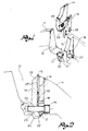
- FIG. 1 represents part of a milling body 11, with one of its peripheral slots 12, designed to house a cutting insert or knife 13, with the help of a blocking pin 14 and at least one tightening screw 15.
- the whole milling body will have as many peripheral slots as there knives to put in them and every knife will be fixed individually in its own slot.
- the slot 12 has one side (on the right in the drawings) with a flat surface 16 for pressing against the knife 13 and, at the internal end of said surface, a shoulder 17 for the support and radial positioning of said knife 13.
- the latter has at least one reference and safety pin 18, jutting out from the flat support surface 16 and into a slotted hole 19 in the knife 13.
- the knife may be equipped with a pair of parallel slotted holes for a corresponding number of reference and safety pins. Furthermore, in certain cases, especially with knives of small dimension, one single hole may accommodate two reference pins for the centering and anti-rotation of the knife.
- the slot 12 has a recess 20 that is angled with respect to the flat support surface 16 of the knife 13, and facing in the opposite direction (backwards) to that of the rotation of the milling machine. More specifically, said recess 20 defines an undercut 21, angled inwards below the shoulder 17, forming an obtuse angle with the support surface 16 of the knife.
- the blocking pin 14 has a top part 22 with a front surface 22' for supporting and blocking the knife 13 and a lower angled portion 23 which extends into the angled recess 20 and terminates in a heel 23' that acts as fulcrum and support against the inclined undercut 21 of said recess.
- the tightening screw 15 passes through a hole 24 in the milling body 11 in a perpendicular direction to the support surface 16 of the knife 13, below the shoulder 17, that is, at the level of the bottom recess 20.
- This tightening screw 15 turns in a threaded hole 25, situated in the lower part 23 of the blocking pin 14, in such a way as to block the latter against the knife 13 and against the inclined undercut 21.
- the support of the portion 22 of the blocking pin 14 for the knife 13 ensures that the latter is secure against the tipping moment when the tool is in operation.
- the interaction of the heel 23' of the blocking pin 14 with the inclined undercut effectively resists the centrifugal force to which the knife 14 is subjected when the milling machine rotates.
- the presence of the centrifugal force, with the blocking pin's tendency to move outwards from the milling body, is a favourable condition since it blocks the knife even more securely to the rest of the machine.
- the blocking pin 14 starts to act as a lever with its fulcrum at the level of its heel 23', and with the tendency of the pin to rotate with its upper part 22 towards the knife.
- the fulcrum heel 23' begins to rise along the inclined undercut 21, causing this rotation of the blocking pin towards the knife.
- the shape of the slot 12, particularly the deep recess 20 and, correspondingly, the blocking pin 14, which works as a lever because of the centrifugal force, guarantee the hold on the knife, above all, with the added advantage of minimal obstruction at the base of the pin.
- the fulcrum of the blocking pin represented by its heel 23', moves away from the centre of the milling machine, which means that the recess can be shallower and, without reducing the size of the knife, it is possible to build milling machines with a smaller external diameter.
Landscapes
- Life Sciences & Earth Sciences (AREA)
- Engineering & Computer Science (AREA)
- Mechanical Engineering (AREA)
- Wood Science & Technology (AREA)
- Forests & Forestry (AREA)
- Milling Processes (AREA)
- Crushing And Pulverization Processes (AREA)
- Scissors And Nippers (AREA)
- Adjustment And Processing Of Grains (AREA)
- Milling, Drilling, And Turning Of Wood (AREA)
Applications Claiming Priority (2)
| Application Number | Priority Date | Filing Date | Title |
|---|---|---|---|
| IT1998BS000098U IT244590Y1 (it) | 1998-12-23 | 1998-12-23 | Dispositivo di bloccaggio di un inserto tagliente su un corpo fresa. |
| ITBS980098U | 1998-12-23 |
Publications (2)
| Publication Number | Publication Date |
|---|---|
| EP1013385A1 EP1013385A1 (en) | 2000-06-28 |
| EP1013385B1 true EP1013385B1 (en) | 2006-09-27 |
Family
ID=11346262
Family Applications (1)
| Application Number | Title | Priority Date | Filing Date |
|---|---|---|---|
| EP99830775A Expired - Lifetime EP1013385B1 (en) | 1998-12-23 | 1999-12-15 | Blocking device for a cutting insert on a milling machine |
Country Status (7)
| Country | Link |
|---|---|
| EP (1) | EP1013385B1 (da) |
| AT (1) | ATE340680T1 (da) |
| DE (1) | DE69933354T2 (da) |
| DK (1) | DK1013385T3 (da) |
| ES (1) | ES2274612T3 (da) |
| IT (1) | IT244590Y1 (da) |
| PT (1) | PT1013385E (da) |
Families Citing this family (2)
| Publication number | Priority date | Publication date | Assignee | Title |
|---|---|---|---|---|
| JPS5213571B2 (da) * | 1974-05-20 | 1977-04-15 | ||
| EP1574308A3 (en) * | 2004-03-09 | 2005-11-16 | STARK S.p.A. | Milling tool |
Family Cites Families (3)
| Publication number | Priority date | Publication date | Assignee | Title |
|---|---|---|---|---|
| US1785151A (en) * | 1929-05-20 | 1930-12-16 | Charles B Sprague | Knife-holding means for chipping machines |
| IT1225109B (it) * | 1988-06-07 | 1990-11-02 | Vebi Di Biason G & C S N C | Dispositivo per il fissaggio amovibile di coltelli in metallo duro su teste rotanti per la lavorazione di legno o materiali simili. |
| DE9210363U1 (de) * | 1992-08-03 | 1993-01-21 | Gebr. Leitz Gmbh & Co, 7082 Oberkochen | Messerkopf, insbesondere Profilmesserkopf |
-
1998
- 1998-12-23 IT IT1998BS000098U patent/IT244590Y1/it active
-
1999
- 1999-12-15 ES ES99830775T patent/ES2274612T3/es not_active Expired - Lifetime
- 1999-12-15 DE DE69933354T patent/DE69933354T2/de not_active Expired - Lifetime
- 1999-12-15 PT PT99830775T patent/PT1013385E/pt unknown
- 1999-12-15 AT AT99830775T patent/ATE340680T1/de active
- 1999-12-15 EP EP99830775A patent/EP1013385B1/en not_active Expired - Lifetime
- 1999-12-15 DK DK99830775T patent/DK1013385T3/da active
Also Published As
| Publication number | Publication date |
|---|---|
| PT1013385E (pt) | 2006-12-29 |
| EP1013385A1 (en) | 2000-06-28 |
| DK1013385T3 (da) | 2007-01-29 |
| IT244590Y1 (it) | 2002-03-12 |
| DE69933354D1 (de) | 2006-11-09 |
| ITBS980098U1 (it) | 2000-06-23 |
| ES2274612T3 (es) | 2007-05-16 |
| DE69933354T2 (de) | 2007-08-23 |
| ATE340680T1 (de) | 2006-10-15 |
Similar Documents
| Publication | Publication Date | Title |
|---|---|---|
| US5993118A (en) | Tool for grooving and parting method of manufacturing same | |
| KR100830323B1 (ko) | 절삭 공구 및 그에 대한 절삭 인서트 | |
| EP2077171B1 (en) | Cutting tool having cutting insert secured by non-penetrating abutment of a threaded fastener | |
| KR100626926B1 (ko) | 절삭 인서트 클램핑 기구 | |
| EP1113895B1 (en) | Drill tool assembly | |
| US20020053266A1 (en) | Positional adjusting mechanism for a cutting insert | |
| JP4327367B2 (ja) | 突切り及び類似作業用の切削工具 | |
| JPH0825089B2 (ja) | カッター・ヘッド | |
| KR970004869B1 (ko) | 구멍 절삭 공구 | |
| SE531502C2 (sv) | Verktyg för spånavskiljande bearbetning samt grundkropp och indexerbart skär härför | |
| CN101795799A (zh) | 切削工具 | |
| KR20090101178A (ko) | 특히 그루빙 공구용의 공구 홀더 및 공구 홀더용 절삭체 | |
| EP1013385B1 (en) | Blocking device for a cutting insert on a milling machine | |
| US7189031B2 (en) | Toolholder with insert clamp and method for the same | |
| US5816751A (en) | Wedging system for replaceable cutting blade inserts | |
| EP4082734A1 (en) | Cutting head for a machinery suitable for carrying out machining by chip removal on materials | |
| JP2812677B2 (ja) | スローアウェイチップのクランプ機構 | |
| AU619709B1 (en) | Rotary saw cutting tool | |
| JP3345343B2 (ja) | 回転刃物装置 | |
| SU1609680A1 (ru) | Дискова пила | |
| SU1563846A1 (ru) | Режущий инструмент | |
| JPH06155113A (ja) | 切削加工用工具 | |
| SE508453C2 (sv) | Skärhållare | |
| AU1901892A (en) | Tool holder for clamping inserts, using a resilient l-shaped clamp | |
| JPH0724514U (ja) | スローアウェイ式カッタのクランプ構造 |
Legal Events
| Date | Code | Title | Description |
|---|---|---|---|
| PUAI | Public reference made under article 153(3) epc to a published international application that has entered the european phase |
Free format text: ORIGINAL CODE: 0009012 |
|
| AK | Designated contracting states |
Kind code of ref document: A1 Designated state(s): AT BE CH CY DE DK ES FI FR GB GR IE IT LI LU MC NL PT SE |
|
| AX | Request for extension of the european patent |
Free format text: AL;LT;LV;MK;RO;SI |
|
| 17P | Request for examination filed |
Effective date: 20001214 |
|
| AKX | Designation fees paid |
Free format text: AT BE CH CY DE DK ES FI FR GB GR IE IT LI LU MC NL PT SE |
|
| GRAP | Despatch of communication of intention to grant a patent |
Free format text: ORIGINAL CODE: EPIDOSNIGR1 |
|
| GRAS | Grant fee paid |
Free format text: ORIGINAL CODE: EPIDOSNIGR3 |
|
| GRAA | (expected) grant |
Free format text: ORIGINAL CODE: 0009210 |
|
| AK | Designated contracting states |
Kind code of ref document: B1 Designated state(s): AT BE CH CY DE DK ES FI FR GB GR IE IT LI LU MC NL PT SE |
|
| PG25 | Lapsed in a contracting state [announced via postgrant information from national office to epo] |
Ref country code: NL Free format text: LAPSE BECAUSE OF FAILURE TO SUBMIT A TRANSLATION OF THE DESCRIPTION OR TO PAY THE FEE WITHIN THE PRESCRIBED TIME-LIMIT Effective date: 20060927 Ref country code: LI Free format text: LAPSE BECAUSE OF FAILURE TO SUBMIT A TRANSLATION OF THE DESCRIPTION OR TO PAY THE FEE WITHIN THE PRESCRIBED TIME-LIMIT Effective date: 20060927 Ref country code: FI Free format text: LAPSE BECAUSE OF FAILURE TO SUBMIT A TRANSLATION OF THE DESCRIPTION OR TO PAY THE FEE WITHIN THE PRESCRIBED TIME-LIMIT Effective date: 20060927 Ref country code: CH Free format text: LAPSE BECAUSE OF FAILURE TO SUBMIT A TRANSLATION OF THE DESCRIPTION OR TO PAY THE FEE WITHIN THE PRESCRIBED TIME-LIMIT Effective date: 20060927 Ref country code: BE Free format text: LAPSE BECAUSE OF FAILURE TO SUBMIT A TRANSLATION OF THE DESCRIPTION OR TO PAY THE FEE WITHIN THE PRESCRIBED TIME-LIMIT Effective date: 20060927 |
|
| REG | Reference to a national code |
Ref country code: GB Ref legal event code: FG4D |
|
| REG | Reference to a national code |
Ref country code: CH Ref legal event code: EP |
|
| REG | Reference to a national code |
Ref country code: IE Ref legal event code: FG4D |
|
| REF | Corresponds to: |
Ref document number: 69933354 Country of ref document: DE Date of ref document: 20061109 Kind code of ref document: P |
|
| PG25 | Lapsed in a contracting state [announced via postgrant information from national office to epo] |
Ref country code: IE Free format text: LAPSE BECAUSE OF NON-PAYMENT OF DUE FEES Effective date: 20061215 |
|
| PG25 | Lapsed in a contracting state [announced via postgrant information from national office to epo] |
Ref country code: SE Free format text: LAPSE BECAUSE OF FAILURE TO SUBMIT A TRANSLATION OF THE DESCRIPTION OR TO PAY THE FEE WITHIN THE PRESCRIBED TIME-LIMIT Effective date: 20061227 |
|
| REG | Reference to a national code |
Ref country code: PT Ref legal event code: SC4A Free format text: AVAILABILITY OF NATIONAL TRANSLATION Effective date: 20061013 |
|
| PG25 | Lapsed in a contracting state [announced via postgrant information from national office to epo] |
Ref country code: MC Free format text: LAPSE BECAUSE OF NON-PAYMENT OF DUE FEES Effective date: 20061231 |
|
| REG | Reference to a national code |
Ref country code: DK Ref legal event code: T3 |
|
| NLV1 | Nl: lapsed or annulled due to failure to fulfill the requirements of art. 29p and 29m of the patents act | ||
| ET | Fr: translation filed | ||
| REG | Reference to a national code |
Ref country code: CH Ref legal event code: PL |
|
| REG | Reference to a national code |
Ref country code: ES Ref legal event code: FG2A Ref document number: 2274612 Country of ref document: ES Kind code of ref document: T3 |
|
| GBPC | Gb: european patent ceased through non-payment of renewal fee |
Effective date: 20061227 |
|
| PLBE | No opposition filed within time limit |
Free format text: ORIGINAL CODE: 0009261 |
|
| STAA | Information on the status of an ep patent application or granted ep patent |
Free format text: STATUS: NO OPPOSITION FILED WITHIN TIME LIMIT |
|
| 26N | No opposition filed |
Effective date: 20070628 |
|
| PG25 | Lapsed in a contracting state [announced via postgrant information from national office to epo] |
Ref country code: GB Free format text: LAPSE BECAUSE OF NON-PAYMENT OF DUE FEES Effective date: 20061227 |
|
| PG25 | Lapsed in a contracting state [announced via postgrant information from national office to epo] |
Ref country code: GR Free format text: LAPSE BECAUSE OF FAILURE TO SUBMIT A TRANSLATION OF THE DESCRIPTION OR TO PAY THE FEE WITHIN THE PRESCRIBED TIME-LIMIT Effective date: 20061228 |
|
| PG25 | Lapsed in a contracting state [announced via postgrant information from national office to epo] |
Ref country code: LU Free format text: LAPSE BECAUSE OF NON-PAYMENT OF DUE FEES Effective date: 20061215 |
|
| PG25 | Lapsed in a contracting state [announced via postgrant information from national office to epo] |
Ref country code: CY Free format text: LAPSE BECAUSE OF FAILURE TO SUBMIT A TRANSLATION OF THE DESCRIPTION OR TO PAY THE FEE WITHIN THE PRESCRIBED TIME-LIMIT Effective date: 20060927 |
|
| REG | Reference to a national code |
Ref country code: FR Ref legal event code: PLFP Year of fee payment: 17 |
|
| PGFP | Annual fee paid to national office [announced via postgrant information from national office to epo] |
Ref country code: DK Payment date: 20151210 Year of fee payment: 17 |
|
| PGFP | Annual fee paid to national office [announced via postgrant information from national office to epo] |
Ref country code: AT Payment date: 20151125 Year of fee payment: 17 Ref country code: ES Payment date: 20151112 Year of fee payment: 17 Ref country code: PT Payment date: 20151214 Year of fee payment: 17 Ref country code: FR Payment date: 20151110 Year of fee payment: 17 |
|
| PGFP | Annual fee paid to national office [announced via postgrant information from national office to epo] |
Ref country code: DE Payment date: 20151217 Year of fee payment: 17 |
|
| REG | Reference to a national code |
Ref country code: DE Ref legal event code: R119 Ref document number: 69933354 Country of ref document: DE |
|
| REG | Reference to a national code |
Ref country code: DK Ref legal event code: EBP Effective date: 20161231 |
|
| REG | Reference to a national code |
Ref country code: AT Ref legal event code: MM01 Ref document number: 340680 Country of ref document: AT Kind code of ref document: T Effective date: 20161215 |
|
| PG25 | Lapsed in a contracting state [announced via postgrant information from national office to epo] |
Ref country code: PT Free format text: LAPSE BECAUSE OF NON-PAYMENT OF DUE FEES Effective date: 20170616 |
|
| REG | Reference to a national code |
Ref country code: FR Ref legal event code: ST Effective date: 20170831 |
|
| PG25 | Lapsed in a contracting state [announced via postgrant information from national office to epo] |
Ref country code: FR Free format text: LAPSE BECAUSE OF NON-PAYMENT OF DUE FEES Effective date: 20170102 Ref country code: AT Free format text: LAPSE BECAUSE OF NON-PAYMENT OF DUE FEES Effective date: 20161215 |
|
| PG25 | Lapsed in a contracting state [announced via postgrant information from national office to epo] |
Ref country code: DE Free format text: LAPSE BECAUSE OF NON-PAYMENT OF DUE FEES Effective date: 20170701 |
|
| PG25 | Lapsed in a contracting state [announced via postgrant information from national office to epo] |
Ref country code: DK Free format text: LAPSE BECAUSE OF NON-PAYMENT OF DUE FEES Effective date: 20161231 |
|
| PGFP | Annual fee paid to national office [announced via postgrant information from national office to epo] |
Ref country code: IT Payment date: 20171215 Year of fee payment: 19 |
|
| PG25 | Lapsed in a contracting state [announced via postgrant information from national office to epo] |
Ref country code: ES Free format text: LAPSE BECAUSE OF FAILURE TO SUBMIT A TRANSLATION OF THE DESCRIPTION OR TO PAY THE FEE WITHIN THE PRESCRIBED TIME-LIMIT Effective date: 20060927 |
|
| REG | Reference to a national code |
Ref country code: ES Ref legal event code: FD2A Effective date: 20181114 |
|
| PG25 | Lapsed in a contracting state [announced via postgrant information from national office to epo] |
Ref country code: ES Free format text: LAPSE BECAUSE OF FAILURE TO SUBMIT A TRANSLATION OF THE DESCRIPTION OR TO PAY THE FEE WITHIN THE PRESCRIBED TIME-LIMIT Effective date: 20161216 |
|
| PG25 | Lapsed in a contracting state [announced via postgrant information from national office to epo] |
Ref country code: IT Free format text: LAPSE BECAUSE OF NON-PAYMENT OF DUE FEES Effective date: 20181215 |