EP1013450A2 - Système hydraulique pour plusieurs têtes d'impression - Google Patents
Système hydraulique pour plusieurs têtes d'impression Download PDFInfo
- Publication number
- EP1013450A2 EP1013450A2 EP99309506A EP99309506A EP1013450A2 EP 1013450 A2 EP1013450 A2 EP 1013450A2 EP 99309506 A EP99309506 A EP 99309506A EP 99309506 A EP99309506 A EP 99309506A EP 1013450 A2 EP1013450 A2 EP 1013450A2
- Authority
- EP
- European Patent Office
- Prior art keywords
- ink
- print heads
- fluid system
- multiple print
- single fluid
- Prior art date
- Legal status (The legal status is an assumption and is not a legal conclusion. Google has not performed a legal analysis and makes no representation as to the accuracy of the status listed.)
- Granted
Links
- 239000012530 fluid Substances 0.000 title claims abstract description 52
- 230000005494 condensation Effects 0.000 claims description 7
- 238000009833 condensation Methods 0.000 claims description 7
- 238000010438 heat treatment Methods 0.000 claims description 4
- 238000012544 monitoring process Methods 0.000 claims 1
- 238000005086 pumping Methods 0.000 claims 1
- 238000012163 sequencing technique Methods 0.000 claims 1
- 238000004140 cleaning Methods 0.000 abstract description 3
- 239000000976 ink Substances 0.000 description 72
- 239000003570 air Substances 0.000 description 8
- 230000001276 controlling effect Effects 0.000 description 3
- 210000000744 eyelid Anatomy 0.000 description 3
- 230000010354 integration Effects 0.000 description 2
- 238000000034 method Methods 0.000 description 2
- 230000001105 regulatory effect Effects 0.000 description 2
- 239000012080 ambient air Substances 0.000 description 1
- 238000012937 correction Methods 0.000 description 1
- 230000003247 decreasing effect Effects 0.000 description 1
- 238000013461 design Methods 0.000 description 1
- 238000010586 diagram Methods 0.000 description 1
- 239000000428 dust Substances 0.000 description 1
- 238000012986 modification Methods 0.000 description 1
- 230000004048 modification Effects 0.000 description 1
- 230000003287 optical effect Effects 0.000 description 1
- 238000013021 overheating Methods 0.000 description 1
- 230000008569 process Effects 0.000 description 1
- 230000000638 stimulation Effects 0.000 description 1
- 238000012360 testing method Methods 0.000 description 1
Images

Classifications
-
- B—PERFORMING OPERATIONS; TRANSPORTING
- B41—PRINTING; LINING MACHINES; TYPEWRITERS; STAMPS
- B41J—TYPEWRITERS; SELECTIVE PRINTING MECHANISMS, i.e. MECHANISMS PRINTING OTHERWISE THAN FROM A FORME; CORRECTION OF TYPOGRAPHICAL ERRORS
- B41J2/00—Typewriters or selective printing mechanisms characterised by the printing or marking process for which they are designed
- B41J2/005—Typewriters or selective printing mechanisms characterised by the printing or marking process for which they are designed characterised by bringing liquid or particles selectively into contact with a printing material
- B41J2/01—Ink jet
- B41J2/17—Ink jet characterised by ink handling
- B41J2/175—Ink supply systems ; Circuit parts therefor
Definitions
- the present invention relates to continuous ink-jet printers and, more particularly, to the operation and control of multiple print heads from a single fluid controller for a continuous ink-jet printer.
- Prior art ink jet printers have typically consisted of two main components, a fluid system and a print head.
- the fluid system controls solenoid valves, pumps, and sensors to help clean, shutdown, and ready the print head for printing. All of the components are designated to a single print head as described in U.S. Patent Nos. 5,394,177 and 4,734,711, totally incorporated herein by reference.
- the ink concentration can drift somewhat. This can lead to a drift in the darkness of the print. This drift of darkness is not noticeable by itself. However, if two print heads are printing side-by-side, the contrast differences can become noticeable.
- Separate print heads are used for each color of ink used by the customer. As different print jobs may require different inks, customers may have more than one type or color of ink in their plant.
- each print head operates independently, as if it were controlled by its own fluid system. This means that each one of the multiple print heads has the capability of cleaning, shutting down, and printing without any interference from the other, while sharing similar components.
- a single fluid system simultaneously and independently controls multiple print heads of a continuous ink jet printer.
- An ink reservoir supplies ink to the multiple print heads and a common vacuum system withdraws ink from the multiple print heads back to the ink reservoir.
- the system controls the concentration of ink to the multiple print heads and separately supplies ink to the multiple print heads.
- Fig. 1 a block diagram of a prior art fluid system 10 is illustrated.
- the fluid system 10 is attached to the print head 12 by means of a flexible umbilical 14.
- the umbilical 14 connection carries fluid to and from the print head 12.
- the umbilical 14 also carries electrical signals to and from a control means 16, such as a computer, that controls the print head 12 functions.
- the print head functions that are controlled include operation of a retractable catch pan or "eyelid" 18 for startup and shutdown.
- the eyelid 18 also allows jets, once formed, to flow into the catcher 22 such that a charge plate 24 of the ink jet printer does not get wet.
- the print head 12 functions that are controlled also include proper fluid pressure, stimulation voltage, and charge voltage, as well as ink heating during startup, and catcher 22 and charge plate 24 heating to remove condensation at the catcher 22.
- the print head 12 communicates with the control means 16 during printing to control these functions.
- prior art fluid system 10 includes a pressure control means associated with the control means 16 to increase or decrease voltage to an ink pump 26.
- the pressure control means is necessary for printing, as well as other pressure levels during startup and shutdown.
- the pressure control means includes a pressure transducer 28 located at the print head 12 for providing the control means 16 with a voltage level, preferably between 0.5 and 4.5 volts, that corresponds to the actual ink pressure at the print head 12.
- a comparison means associated with the control means 16 then compares the actual ink pressure with a desired ink pressure and provides a comparison value. This comparison value is used by the computer 16 to adjust a pulse-width-modulated voltage to the ink pump 26 to attain the desired ink pressure. If the actual ink pressure is high or low in comparison to the desired ink pressure, then the computer 16 adjusts the pulse width modulated voltage to the ink pump 26 accordingly. This correction can occur almost continuously, on the order of up to forty times per second.
- the fluid system 10 includes an optical concentration sensor 30, whereby ink from an ink supply 44 or a replenishment supply 48 is added to a fluid supply 46 to provide the proper dye level.
- An ink temperature control means comprises an ink temperature sensor 50, an ink heater 52 and an ambient temperature sensor 54 associated with the control means 16 for controlling ink temperature.
- the ink temperature control is provided mainly for the purpose of accomplishing the startup process required to startup the fluid system 10.
- the ink temperature control means comprises means for heating the ink sufficiently to place condensation on the charge plate 24 leads, to wash any ink left from the startup procedure down to the catcher 22.
- the fluid system 10 also includes a vacuum control means 56 for controlling vacuum during startup, shutdown, and printing.
- a vacuum transducer 58 is located in the fluid system 10 which measures vacuum level. This information is provided to the control means 16 to control the vacuum.
- the vacuum control 56 is preferably provided by a stepper motor 60 which effectively controls flow into a secondary or bypass line 74 attached to an ambient air inlet 76 of a vacuum pump 78. This, in turn, changes the system 10 vacuum to the desired value.
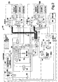
- a single fluid system 100 capable of independently and simultaneously controlling the integration of multiple print heads.
- the integration of two print heads supported by one fluid system involves both shared and additional components from the existing fluid system, and new components which enable the operation of the system.
- each print head is controlled by a separate print head interface controller (PIC) box 102a and 102b, and share a common ink reservoir or ink tank 104.
- PIC print head interface controller
- the ink tank is under vacuum supplied by regulated vacuum systems means.
- Regulated vacuum system means could be of the type described in patent 5,394,177 or, in a preferred embodiment, as described in co-pending, commonly assigned patent application Serial No. , (Attorney Docket No. SDP231PA).
- Ink is withdrawn from the ink tank 104 by ink pumps 110, each of which supply ink to a single print heads.
- Each pump 110 is driven by a variable speed brushless VDC motor which allows control of the flow rate to each print head, similar to the existing fluid system. It is important to note that with the addition of variable flow controlled solenoid valves, one ink pump would be sufficient to supply ink to both print heads. However, other design parameters may require each print head to be assigned its own ink pump.
- each print head also has an individual ink heater of any suitable type, such as a heated umbilical 112, as is described and claimed in commonly assigned, copending patent application Serial No. , (Attorney Docket No. SDP211PA).
- a common heater controller means is used to control the two ink heaters. This controller monitors the ink temperature in each print head by means of separate temperature sensors 114 and energizes and deenergizes the ink heaters by means of separate heater control relays (not shown) to provide separate servo control of the ink temperature for the two print heads. To minimize the electromagnetic emissions, the switching of the heater power is done at the crossover points of the AC sine wave.
- the common heater controller ensures that both heaters are not energized at the same time. Rather it shares the heater power in a ping-pong fashion between the two heaters. Furthermore, during the start up sequence it is desirable for the ink temperature in the print head to rise rapidly to produce the condensation needed for cleaning the charge plate. To provide the desired rapid temperature the system controller staggers the startup sequence for the two print heads so that the heater controller can supply full power to a single heater for the time required to get the desired condensation before switching the power to the next heater to produce the desired condensation for the next print head. In this manner, the single common heater controller for the two print heads, can significantly reduce the peak current requirements for a multiple print head system.
- the separate ink heaters have separate thermostats (not shown) which protect the system from overheating, these thermostats are not used for temperature control.
- a concentration control sensor 124 monitors the ink concentration. Ink is circulated through the concentration sensor from the ink tank by a small separate fluid pump 126. In this way, the flow through the sensor is independent of the flow to either of the print heads.
- the concentration control system is configured such that when the fluid system 100 fills with fresh ink, ink passes through a valve 128 at the inlet of the concentration sensor and passes through the sensor. In this way, the sensor can be calibrated against fresh ink.
- the fluid system control electronics monitors the output of this sensor and the output of the ink tank level sensors as it controls the addition of ink or a replenishment fluid to the ink tank, similar to the existing fluid system.
- Checking the concentration of make up ink with the concentration sensor as the ink is added to the fluid system can also provide a failsafe test to prevent the wrong type or color of ink from being added to the fluid system.
- Positive air pumps have been employed in existing products to help keep dust and debris out of the print head.
- the positive air pump supplies clean air not to the enclosed print head, but into the fluid lines.
- the positive air pump in fluid system 100 provides clean air through air valves 180 to each droplet generator to help remove ink from the print heads during shutdown of both print heads. The function of this air pump is described in more detail in commonly assigned, copending patent application Serial No. , (Attorney Docket No. SDP217), totally incorporated herein by reference.
- the independent and simultaneous operation of multiple print heads from one fluid system in a continuous ink-jet printer gives the ability to print wide swath high quality images, saving both cost and space from the existing fluid system, as well as maintaining a consistent concentration of ink for the two print heads.
Landscapes
- Ink Jet (AREA)
Applications Claiming Priority (2)
| Application Number | Priority Date | Filing Date | Title |
|---|---|---|---|
| US21166498A | 1998-12-14 | 1998-12-14 | |
| US211664 | 1998-12-14 |
Publications (3)
| Publication Number | Publication Date |
|---|---|
| EP1013450A2 true EP1013450A2 (fr) | 2000-06-28 |
| EP1013450A3 EP1013450A3 (fr) | 2001-02-07 |
| EP1013450B1 EP1013450B1 (fr) | 2006-07-19 |
Family
ID=22787865
Family Applications (1)
| Application Number | Title | Priority Date | Filing Date |
|---|---|---|---|
| EP19990309506 Expired - Lifetime EP1013450B1 (fr) | 1998-12-14 | 1999-11-29 | Système hydraulique pour plusieurs têtes d'impression |
Country Status (4)
| Country | Link |
|---|---|
| EP (1) | EP1013450B1 (fr) |
| JP (1) | JP2000218833A (fr) |
| CA (1) | CA2292407A1 (fr) |
| DE (1) | DE69932395T2 (fr) |
Cited By (20)
| Publication number | Priority date | Publication date | Assignee | Title |
|---|---|---|---|---|
| EP1932671A1 (fr) * | 2006-12-11 | 2008-06-18 | Agfa Graphics N.V. | Dispositif pour régler la pression dans une imprimante à navette |
| WO2010138191A1 (fr) | 2009-05-29 | 2010-12-02 | Eastman Kodak Company | Compositions aqueuses présentant des caractéristiques améliorées de corrosion du silicium |
| WO2011066117A1 (fr) | 2009-11-24 | 2011-06-03 | Eastman Kodak Company | Composition aqueuse d'encre pour imprimante à jet d'encre continu |
| WO2011066091A1 (fr) | 2009-11-24 | 2011-06-03 | Eastman Kodak Company | Composition d'encre aqueuse pour imprimante à jet d'encre continu |
| WO2011082721A1 (fr) * | 2009-12-15 | 2011-07-14 | Till, Volker | Installation destinée à l'impression de récipients |
| WO2012030546A1 (fr) | 2010-08-31 | 2012-03-08 | Eastman Kodak Company | Fluide d'impression à jet d'encre |
| WO2012030553A2 (fr) | 2010-08-31 | 2012-03-08 | Eastman Kodak Company | Système et procédé d'impression à fluide remis en circulation |
| WO2012134783A2 (fr) | 2011-03-31 | 2012-10-04 | Eastman Kodak Company | Jeu d'encres d'impression au jet d'encre |
| US8282202B2 (en) | 2010-10-29 | 2012-10-09 | Eastman Kodak Company | Aqueous inkjet printing fluid compositions |
| WO2012149324A1 (fr) | 2011-04-29 | 2012-11-01 | Eastman Kodak Company | Remise en circulation d'un liquide pour l'impression par jet d'encre, système et procédé |
| WO2013032826A1 (fr) | 2011-08-31 | 2013-03-07 | Eastman Kodak Company | Procédé d'impression à jet d'encre continu et ensemble de fluide |
| US8398223B2 (en) | 2011-03-31 | 2013-03-19 | Eastman Kodak Company | Inkjet printing process |
| US8459787B2 (en) | 2010-10-29 | 2013-06-11 | Eastman Kodak Company | Aqueous inkjet printing fluid compositions |
| US8465142B2 (en) | 2010-10-29 | 2013-06-18 | Eastman Kodak Company | Aqueous inkjet printing fluid compositions |
| US8480224B2 (en) | 2010-10-29 | 2013-07-09 | Eastman Kodak Company | Aqueous inkjet printing fluid compositions |
| US8485654B2 (en) | 2010-10-29 | 2013-07-16 | Eastman Kodak Company | Aqueous inkjet printing fluid compositions |
| WO2014127087A2 (fr) | 2013-02-18 | 2014-08-21 | Eastman Kodak Company | Composition pour imprimante à jet d'encre et utilisation |
| US8911067B2 (en) | 2013-02-11 | 2014-12-16 | Eastman Kodak Company | Printing liquid transfer and supply system |
| WO2015199983A1 (fr) | 2014-06-23 | 2015-12-30 | Eastman Kodak Company | Fluide d'impression à jet d'encre à recirculation |
| WO2020040993A1 (fr) | 2018-08-21 | 2020-02-27 | Eastman Kodak Company | Compositions aqueuses de prétraitement et articles préparés à partir de celles-ci |
Families Citing this family (8)
| Publication number | Priority date | Publication date | Assignee | Title |
|---|---|---|---|---|
| EP2756044B1 (fr) | 2011-09-16 | 2018-05-30 | Eastman Kodak Company | Composition d'encre pour un imprimante à jet d'encre continu |
| US11185452B2 (en) | 2018-10-26 | 2021-11-30 | The Procter & Gamble Company | Absorbent article with graphics printed in preservative-free ink, and methods of manufacture thereof |
| EP3870653B1 (fr) | 2018-10-26 | 2022-12-21 | Eastman Kodak Company | Encre aqueuse pour impression par jet d'encre et ensemble d'encres |
| US11376343B2 (en) | 2018-10-26 | 2022-07-05 | The Procter & Gamble Company | Absorbent article with graphics printed in preservative-free ink, and methods of manufacture thereof |
| CN114364756A (zh) | 2019-08-27 | 2022-04-15 | 伊斯曼柯达公司 | 用于喷墨印刷的方法和油墨套装 |
| DE102019123164B3 (de) | 2019-08-29 | 2020-07-02 | Koenig & Bauer Ag | Tintenstrahldruckmaschine und ein Verfahren zum Betreiben einer Tintenstrahldruckmaschine mit Druckregulierung |
| EP4232296A1 (fr) | 2020-10-20 | 2023-08-30 | Eastman Kodak Company | Compositions aqueuses et revêtements opaques obtenus à partir de ces dernières |
| CN119907838A (zh) | 2022-09-14 | 2025-04-29 | 伊斯曼柯达公司 | 印刷荧光水性有色墨和喷墨印刷的方法 |
Citations (2)
| Publication number | Priority date | Publication date | Assignee | Title |
|---|---|---|---|---|
| US4734711A (en) | 1986-12-22 | 1988-03-29 | Eastman Kodak Company | Pressure regulation system for multi-head ink jet printing apparatus |
| US5394177A (en) | 1992-05-29 | 1995-02-28 | Scitex Digital Printing, Inc. | Four inch fluid system |
Family Cites Families (8)
| Publication number | Priority date | Publication date | Assignee | Title |
|---|---|---|---|---|
| US4067020A (en) * | 1976-09-20 | 1978-01-03 | A. B. Dick Company | Noninterrupt ink transfer system for ink jet printer |
| US4340896A (en) * | 1980-12-22 | 1982-07-20 | Pitney Bowes Inc. | Impulse ink jet ink delivery apparatus |
| US4658272A (en) * | 1981-10-02 | 1987-04-14 | Canon Kabushiki Kaisha | Ink-supplying device |
| US4413267A (en) * | 1981-12-18 | 1983-11-01 | Centronics Data Computer Corp. | Ink supply system for ink jet printing apparatus |
| DE3446998A1 (de) * | 1983-12-26 | 1985-07-04 | Canon K.K., Tokio/Tokyo | Tintenstrahl-aufzeichnungsgeraet |
| US5343226A (en) * | 1990-09-28 | 1994-08-30 | Dataproducts Corporation | Ink jet ink supply apparatus |
| EP0714779B1 (fr) * | 1994-11-30 | 2003-03-12 | Canon Kabushiki Kaisha | Appareil d'impression à jet d'encre |
| ATE208278T1 (de) * | 1996-05-22 | 2001-11-15 | Marconi Data Systems Inc | Tintendruckkopfmodule mit gemeinsamer tintenzufuhr |
-
1999
- 1999-11-29 DE DE69932395T patent/DE69932395T2/de not_active Expired - Lifetime
- 1999-11-29 EP EP19990309506 patent/EP1013450B1/fr not_active Expired - Lifetime
- 1999-12-10 CA CA 2292407 patent/CA2292407A1/fr not_active Abandoned
- 1999-12-14 JP JP35484799A patent/JP2000218833A/ja active Pending
Patent Citations (2)
| Publication number | Priority date | Publication date | Assignee | Title |
|---|---|---|---|---|
| US4734711A (en) | 1986-12-22 | 1988-03-29 | Eastman Kodak Company | Pressure regulation system for multi-head ink jet printing apparatus |
| US5394177A (en) | 1992-05-29 | 1995-02-28 | Scitex Digital Printing, Inc. | Four inch fluid system |
Cited By (28)
| Publication number | Priority date | Publication date | Assignee | Title |
|---|---|---|---|---|
| WO2008071609A1 (fr) * | 2006-12-11 | 2008-06-19 | Agfa Graphics Nv | Dispositif de commande de pression monté sur une navette pour imprimante à jet d'encre |
| EP1932671A1 (fr) * | 2006-12-11 | 2008-06-18 | Agfa Graphics N.V. | Dispositif pour régler la pression dans une imprimante à navette |
| WO2010138191A1 (fr) | 2009-05-29 | 2010-12-02 | Eastman Kodak Company | Compositions aqueuses présentant des caractéristiques améliorées de corrosion du silicium |
| US8419176B2 (en) | 2009-05-29 | 2013-04-16 | Eastman Kodak Company | Aqueous compositions with improved silicon corrosion characteristics |
| WO2011066117A1 (fr) | 2009-11-24 | 2011-06-03 | Eastman Kodak Company | Composition aqueuse d'encre pour imprimante à jet d'encre continu |
| WO2011066091A1 (fr) | 2009-11-24 | 2011-06-03 | Eastman Kodak Company | Composition d'encre aqueuse pour imprimante à jet d'encre continu |
| CN102753352A (zh) * | 2009-12-15 | 2012-10-24 | 福尔克尔·蒂尔 | 用于容器印刷的设备 |
| WO2011082721A1 (fr) * | 2009-12-15 | 2011-07-14 | Till, Volker | Installation destinée à l'impression de récipients |
| WO2012030553A2 (fr) | 2010-08-31 | 2012-03-08 | Eastman Kodak Company | Système et procédé d'impression à fluide remis en circulation |
| WO2012030546A1 (fr) | 2010-08-31 | 2012-03-08 | Eastman Kodak Company | Fluide d'impression à jet d'encre |
| US8434857B2 (en) | 2010-08-31 | 2013-05-07 | Eastman Kodak Company | Recirculating fluid printing system and method |
| US8430492B2 (en) | 2010-08-31 | 2013-04-30 | Eastman Kodak Company | Inkjet printing fluid |
| US8485654B2 (en) | 2010-10-29 | 2013-07-16 | Eastman Kodak Company | Aqueous inkjet printing fluid compositions |
| US8459787B2 (en) | 2010-10-29 | 2013-06-11 | Eastman Kodak Company | Aqueous inkjet printing fluid compositions |
| US8282202B2 (en) | 2010-10-29 | 2012-10-09 | Eastman Kodak Company | Aqueous inkjet printing fluid compositions |
| US8480224B2 (en) | 2010-10-29 | 2013-07-09 | Eastman Kodak Company | Aqueous inkjet printing fluid compositions |
| US8465142B2 (en) | 2010-10-29 | 2013-06-18 | Eastman Kodak Company | Aqueous inkjet printing fluid compositions |
| WO2012134783A2 (fr) | 2011-03-31 | 2012-10-04 | Eastman Kodak Company | Jeu d'encres d'impression au jet d'encre |
| US8465578B2 (en) | 2011-03-31 | 2013-06-18 | Eastman Kodak Company | Inkjet printing ink set |
| US8398223B2 (en) | 2011-03-31 | 2013-03-19 | Eastman Kodak Company | Inkjet printing process |
| WO2012149324A1 (fr) | 2011-04-29 | 2012-11-01 | Eastman Kodak Company | Remise en circulation d'un liquide pour l'impression par jet d'encre, système et procédé |
| WO2013032826A1 (fr) | 2011-08-31 | 2013-03-07 | Eastman Kodak Company | Procédé d'impression à jet d'encre continu et ensemble de fluide |
| US8764161B2 (en) | 2011-08-31 | 2014-07-01 | Eastman Kodak Company | Printing fluids including a humectant |
| US8911067B2 (en) | 2013-02-11 | 2014-12-16 | Eastman Kodak Company | Printing liquid transfer and supply system |
| WO2014127087A2 (fr) | 2013-02-18 | 2014-08-21 | Eastman Kodak Company | Composition pour imprimante à jet d'encre et utilisation |
| WO2015199983A1 (fr) | 2014-06-23 | 2015-12-30 | Eastman Kodak Company | Fluide d'impression à jet d'encre à recirculation |
| US9523011B2 (en) | 2014-06-23 | 2016-12-20 | Eastman Kodak Company | Recirculating inkjet printing fluid |
| WO2020040993A1 (fr) | 2018-08-21 | 2020-02-27 | Eastman Kodak Company | Compositions aqueuses de prétraitement et articles préparés à partir de celles-ci |
Also Published As
| Publication number | Publication date |
|---|---|
| DE69932395D1 (de) | 2006-08-31 |
| DE69932395T2 (de) | 2007-07-19 |
| EP1013450B1 (fr) | 2006-07-19 |
| EP1013450A3 (fr) | 2001-02-07 |
| JP2000218833A (ja) | 2000-08-08 |
| CA2292407A1 (fr) | 2000-06-14 |
Similar Documents
| Publication | Publication Date | Title |
|---|---|---|
| EP1013450B1 (fr) | Système hydraulique pour plusieurs têtes d'impression | |
| EP0577186B1 (fr) | Tête d'enregistrement par injection d'un liquide et appareil d'enregistrement équipé avec cette tête | |
| CN101352969B (zh) | 液体喷射设备、图像形成设备和液体存储量判断方法 | |
| EP2216178B1 (fr) | Tête d'impression à jet d'encre et appareil de stockage d'encre | |
| JPH06218943A (ja) | 4インチ液体システム | |
| JP2008188987A (ja) | 記録装置及び記録ヘッドの保温制御方法 | |
| EP3795363B1 (fr) | Appareil d'impression et procédé de circulation d'encre | |
| US8985721B2 (en) | Printing apparatus and aging method | |
| US6511145B1 (en) | Method for adjusting an amount of discharge between a plurality of liquid discharge nozzle units, an ink jet driving method using such method of adjustment, and an ink jet apparatus | |
| EP3747657B1 (fr) | Dispositif de décharge de gouttelettes de liquide | |
| JP5422332B2 (ja) | インクジェット印刷装置 | |
| JPH08276575A (ja) | プリント装置 | |
| JP2675910B2 (ja) | インクジェット記録装置 | |
| JP2003039642A (ja) | インクジェット記録装置、及びインクジェット記録装置におけるヘッド温度制御方法 | |
| JP2023042155A (ja) | 液体吐出装置及び制御方法 | |
| US6698858B1 (en) | System and method for decreasing print banding with time delay synchronization of ejected ink | |
| JP2720060B2 (ja) | 回復方法 | |
| US7347520B2 (en) | Inkjet printing apparatus and information processing method | |
| JP2008055716A (ja) | インクジェット記録用ヘッド、及びインクジェット記録装置 | |
| JP6965026B2 (ja) | 記録装置および記録方法 | |
| JP2025144641A (ja) | インクジェット印刷装置 | |
| JP2022121499A (ja) | 記録装置および記録方法 | |
| US7377612B2 (en) | Inkjet recording apparatus | |
| JP6976738B2 (ja) | 記録装置および記録方法 | |
| JPH0584927A (ja) | インクジエツト記録装置 |
Legal Events
| Date | Code | Title | Description |
|---|---|---|---|
| PUAI | Public reference made under article 153(3) epc to a published international application that has entered the european phase |
Free format text: ORIGINAL CODE: 0009012 |
|
| AK | Designated contracting states |
Kind code of ref document: A2 Designated state(s): AT BE CH CY DE DK ES FI FR GB GR IE IT LI LU MC NL PT SE |
|
| AX | Request for extension of the european patent |
Free format text: AL;LT;LV;MK;RO;SI |
|
| PUAL | Search report despatched |
Free format text: ORIGINAL CODE: 0009013 |
|
| AK | Designated contracting states |
Kind code of ref document: A3 Designated state(s): AT BE CH CY DE DK ES FI FR GB GR IE IT LI LU MC NL PT SE |
|
| AX | Request for extension of the european patent |
Free format text: AL;LT;LV;MK;RO;SI |
|
| 17P | Request for examination filed |
Effective date: 20010717 |
|
| AKX | Designation fees paid |
Free format text: DE FR GB |
|
| 17Q | First examination report despatched |
Effective date: 20040310 |
|
| RAP1 | Party data changed (applicant data changed or rights of an application transferred) |
Owner name: EASTMAN KODAK COMPANY |
|
| GRAP | Despatch of communication of intention to grant a patent |
Free format text: ORIGINAL CODE: EPIDOSNIGR1 |
|
| GRAS | Grant fee paid |
Free format text: ORIGINAL CODE: EPIDOSNIGR3 |
|
| GRAA | (expected) grant |
Free format text: ORIGINAL CODE: 0009210 |
|
| AK | Designated contracting states |
Kind code of ref document: B1 Designated state(s): DE FR GB |
|
| REG | Reference to a national code |
Ref country code: GB Ref legal event code: FG4D |
|
| REF | Corresponds to: |
Ref document number: 69932395 Country of ref document: DE Date of ref document: 20060831 Kind code of ref document: P |
|
| ET | Fr: translation filed | ||
| PLBE | No opposition filed within time limit |
Free format text: ORIGINAL CODE: 0009261 |
|
| STAA | Information on the status of an ep patent application or granted ep patent |
Free format text: STATUS: NO OPPOSITION FILED WITHIN TIME LIMIT |
|
| 26N | No opposition filed |
Effective date: 20070420 |
|
| PGFP | Annual fee paid to national office [announced via postgrant information from national office to epo] |
Ref country code: FR Payment date: 20131025 Year of fee payment: 15 Ref country code: GB Payment date: 20131028 Year of fee payment: 15 |
|
| PGFP | Annual fee paid to national office [announced via postgrant information from national office to epo] |
Ref country code: DE Payment date: 20141201 Year of fee payment: 16 |
|
| GBPC | Gb: european patent ceased through non-payment of renewal fee |
Effective date: 20141129 |
|
| REG | Reference to a national code |
Ref country code: FR Ref legal event code: ST Effective date: 20150731 |
|
| PG25 | Lapsed in a contracting state [announced via postgrant information from national office to epo] |
Ref country code: GB Free format text: LAPSE BECAUSE OF NON-PAYMENT OF DUE FEES Effective date: 20141129 |
|
| PG25 | Lapsed in a contracting state [announced via postgrant information from national office to epo] |
Ref country code: FR Free format text: LAPSE BECAUSE OF NON-PAYMENT OF DUE FEES Effective date: 20141201 |
|
| REG | Reference to a national code |
Ref country code: DE Ref legal event code: R119 Ref document number: 69932395 Country of ref document: DE |
|
| PG25 | Lapsed in a contracting state [announced via postgrant information from national office to epo] |
Ref country code: DE Free format text: LAPSE BECAUSE OF NON-PAYMENT OF DUE FEES Effective date: 20160601 |